1
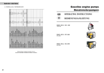
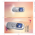
SOMA
INSTALLATION
MANUAL
Manufactured by
SUNRISE SOLAR
49 VISTA AVE NORTH, COPACABANA NSW 2251 AUSTRALIA
PH 61 2 4381 1531 FAX 61 2 4382 1880 EMAIL [email protected]
1
WARRANTY CONDITIONS
Sunrise Solar warrants your Soma1000 / Soma400 to be free of
defects in materials and workmanship under normal use and service,
for a period of one (1) year.
This warranty is available from the date of original purchase. All
parts will be replaced or repaired free of charge within this period and
the unit will be returned at no cost to the owner. Freight charges to
the point of purchase and the cost of any repairs resulting from
damages occurring during this freighting will be borne by the owner.
The provision of this warranty shall not apply if the unit has been
subject to misuse, poor installation, neglect, acts of Nature, accidental
damage or has been used for a purpose for which it is not designed.
The warranty does cover the machine in winds up to 50 metres per
second, but does not cover the machine from the effects of flying
debris or birds.
Any alterations or repairs by unauthorised parties will void your
warranty.
WARRANTY COUPON
Name of Purchaser:........................................................................................
Address of Purchaser:.....................................................................................
.....................................................................................................................
Location of Wind Generator (if not at above address):....................................
.....................................................................................................................
Date of Purchase:....................................
Point of Purchase:.........................................................................................
....................................................................................................................
2
INTRODUCTION
This manual provides technical descriptions, specifications and
installation procedures for the SOMA wind generators.
WIND GENERATOR USAGE
The SOMA Wind Generator is a battery charging wind generator to supply
power for light duty electrical requirements in remote areas. It is
designed to be the main source of power to the energy efficient home
covering such loads as lighting, radio, television, water pump,
washing machine, kitchen blenders, power tools and refrigeration. The
maintenance free features of the SOMA 1000 also make it an ideal
source of power to telecommunications and scientific equipment located
in inaccessable areas.
SOMA wind generators have been designed to be used either as a
complementary power supply in conjunction with one or more
photovoltaic panels; or in particularly windy areas, as a stand-alone
power supply system.
SIMPLE INSTALLATION
It should take two people no more than two days to complete the
installation of the SOMA 1000. Recommendations put forward in this
manual should be adhered to as closely as possible. An improper site
selection or poor installation can seriosly affect the performance of
the system.
PLEASE READ THIS MANUAL CAREFULLY BEFORE BEGINNING
INSTALLATION.
3
LIST OF COMPONENTS
Upon recieving your SOMA you will have the following components that
must be assembled together.
1. blade
2. tail pipe (strapped to blade)
3. tail fin
4. power head
5. propellor bolts
6. nose cone (SOMA 1000 only)
7. controller
THE BLADE
The rotor blades are constructed using a hollow moulded fibre glass
technique that is inique to Soma. High tensile anilinear glass fibres
combined with marine grade resins create a modulus for a blade that is
both strong and light. Stainless steel tape provides long term erosion
protection for the leading edges of the blades.
The blades are in one piece which is pre-balanced and fits into
location over the boss of the rotor hub. Four bolts are used to secure
the blade to the rotor hub.
BLADE CHARACTERISTICS
SOMA 1000
SOMA 400
Rotor diamenter
Chord length: base
tip
Pitch at tip
Twist
Tip speed ratio
2.7 metre
125mm
50mm
2 degrees
7 degrees
10:1
2 metre
125mm
65mm
5 degrees
7 degrees
8:1
ALTERNATOR
The SOMA alternator, which is the main component of the power head is a
brushless, directly-driven, alternating current generator which utilizes a
rotating permanent magnet field.
The alternator is designed to produce a power curve that is optimally
4
suited to the two bladed rotor. The copper windings are impregnated
with resin to protect them from corrosion. The rotor shaft is
stainless steel with sealed ball bearings (bearing number 6205). The
rotor hub is galvanised steel.
The rotor hub of the alternator contains the powerful permanent
magnets which rotate around the 14 pole stator. The alternator
produces 3 phase alternating current (AC) which is converted to direct
current (DC) by the Soma Controllerr which is located near the
batteries.
SWIVEL ASSEMBLY
The swivel assembly rotates and allows the wind generator to face the
wind. It also provides the mechanism by which the rotor can tilt back
out of the wind to prevent overspeeding. Housed within the swivel
assembly are the brushes and slip rings which carry the power to the
cable leading to the batteries. It is made of galvanised steel.
The swivel assembly fits over the top of a 65mm NB galvanised pipe
tower and is secured with 2 bolts. Sealed ball bearings enable free
rotation. (Bearing numbers 6206 and 6007). The tail pipe is secured
inside the stator boss and the tail vane is bolted to the pipe.
THE SOMA CONTROLLER
The controller is located near the batteries which can be located up to
750 metres away from the wind generator depending on system voltage
and cable size. The controller is a charge regulator which protects the
batteries from being overcharged by the wind generator. It contains a
voltage sensing mosfet switching device which switches current across
to a dump load when ever battery voltage reaches a pre-set point.
The controller also contains the rectifier which converts the 3 phase A.C.
voltage generated by the SOMA into D.C. voltage suitable for charging the
battery. An amp meter indicates the amount of current that is being
produced at any time.
FEATHERING MECHANISM
The SOMA 1000 utilizes the proven "tilt-up" feathering method to limit
5
rotor speeds in winds in excess of 15ms (metres per second), or 54
kph. It is necessary to limit rotor speed in strong winds to reduce
the loads on the wind generator and the tower and to prevent blade
wear from overspeeding.
The centre of effort of the rotor is above the pivot point of the
stator, and wind pressure causes the whole assembly to tilt up. This
has the effect of reducing the rotor area presented to the wind, and
results in a limitation of the power and rotational speeds achieved by
the rotor. The stronger the wind, the further back the rotor tilts. As
the wind decreases, gravitational effect pulls the rotor back into
normal operating position. A stainless steel hydraulic dampener
governs the speed at which the feathering action takes place. This
reduces undesirable gyrational action.
TOWERS
There are two types of tower recommended by Sunrise Solar. The first
is a wooden pole which is both an inexpensive and simple solution. The
second is a galvinised pipe tower with a built in winch tilt
mechanism.
WOODEN POLE TOWER
In areas where there is an abundant supply, a wooden pole will make
the most economic and simple tower.
THE POLE
The pole should be a minimum of 7 metres long but preferably 10 or 12
metres long. The diameter of the top of the pole should be 175mm. It
should be of a type of wood which will not decay in the ground. This
can be either a treated soft wood such as tantalised pine or a
hardwood known for its ground retention qualities.
ALSO NEEDED ARE:
1. 65mmNB Galvinised pipe, medium wall, 2.5 metres long.
2. Two 12mm U bolts 300mm long with 75mm ID and backing plates.
3. Approx. 15 steps made from 16mm reinforcing rod 300mm long.
4. Three guy wire anchors: Can be made by bending 12mm reinforcing
rod into U shape to be set in concrete foundation: or, i metre
long x 175mm diameter wooden post buried 1 metre under surface:
6
5.
6.
7.
8.
or, screw-in type anchors as used for electric power poles.
Three turnbuckles or rigging screws strain the rigging tight.
Minimum size 10mm.
6mm Wire rope long enough for 3 guy wires.
Wire rope grips (6 per guy wire, 18 in total).
Concrete for foundation. (rammed earth is another option).
The above listed equipment is available from your Soma dealer.
POLE PREPARATION
Before the pole is raised insert steps and top pipe.
Two steps should be placed 150mm below the pole top to serve as a
working platform. Below this, steps should be placed at 500mm
intervals, alternating from one side of the pole to the other, down to
2 metres above ground level. Two steps should be placed at 1 metre
below the top of the pole to act as supports for the guy wires.
The pole should have a flat face cut in its side for 1 metre below the
top. The top pipe can now be U bolted to this flat face at the top of
the tower. It should extend above the tower by 1.5 metres.
FOUNDATIONS
The hole for the pole should be at least 1.2 metres deep. A trench is
dug in to the side of the hole to guide the pole in to the hole as it
is being raised. If rammed earth is being used instead of concrete,
place a hard wood block at the base of the hole to support the pole.
The 3 guy wire anchors should be set in the ground spaced 120 degrees
apart. The distance out from the base of the pole should be 60% of the
height of the pole.
If concrete foundations are used, the holes should be 500mm x 500mm x
500mm. The end loop of the reinforcing rod anchor should protrude 50mm
above the concrete.
If a wooden post is used, tie the wire rope around the centre of the
post before burying it 1 metre below the surface.
7
65mm NB Galvanising Pipe
2.5m long
1.5m
Nut
U-Bolts
1.0m
Backing Plates
Nut
Side of Pole cut
flat
Plastic Hose
Wire Rope
Grips
Galvanised
Wire Rope
1.0m
Steps
(Ex 16mm
Reinforcing
Bar
Guy Wire
Anchor
Rigging Screw
Ground Level
Concrete (on
rammed earth)
1.2m
Foundation
600x600x600
8
RAISE THE POLE
Secure the three guy wires to the pole. The wire ropes pass around the
back of the pole and on top of one of the steps positioned 1 metre
below the top of the pole. Use 500mm lengths of black plastic water
hose (polypropelene or alkathene) to prevent the wire rope from
chaffing on the back of the pole and on the step. Use three wire grips
per wire.
The pole can be raised by hand, but at least 6 strong people are
needed to do so safely. Alternatively, a tractor or heavy vehicle can
pull the pole up using a 'gin pole'. Two people with ropes on either
side of the gin pole are needed to prevent it from swinging sideways.
Raising the pole can be dangerous. Everyone present should have clear
instructions and no-one should be at risk should the pole fall.
Once the pole is standing in its hole the guy wires can be secured
(possibly to temporary anchors) and the pole made level. It is best to
view the top pipe from two sides from the ground with a spirit level
to ensure it is level. Once vertical, the pole can have the concrete
poured in the hole around it, or, alternatively, earth can be rammed
into the hole.
COMMENT
1.
3.
5.
7.
9.
11.
upper pipe
gin pole
joiner tube
lower guy wires
wire rope grips
foundation rings
While
is
6
or remove or perform
wind generator. For
maintenance, a
winch-tilt tower as
2.
4.
6.
8.
10.
this
lower pipe
hinge bracket
upper guy wires
rigging screws
shackles
type of pole
relatively
cheap to
you have to
it to install
6
install,
climb
1
annual maintenance on the
ease and safety of installation and
5
described next is recommended.
7
7
GALVANISED PIPE
WINCH-TILT TOWER
2
8
10
These towers,
Solar,
9
4 13m,
11
available
come in 4
19.5m and 26m.
3
9
from Sunrise
heights: 6.5m,
WINCH TOWERS
SAFE
&
EASY
features
tower tilts down to the ground
bi-directional brake winch
hot dip galvanised
supplied in kit form with or without poles
19.5m TOWER
Specifications
Height
Base Dimensions
Outside Foundations
Centre Foundation
19.5metres
13.8m x 13.8m
0.7 x 0.7 x 0.7m
1 x 1 x 0.25m deep
benefits
no climbing
no towing
safe
anti corrosion
simplifies installation & maintenance
13m TOWER
Specifications
Height
Base Dimensions
Outside Foundations
Centre Foundation
SUNRISE
10
13 metres
9.2 x 9.2m
0.6 x 0.6 x 0.6m
1 x 1 x 0.25m deep
S
INSTALLATIO
N
&
Available from
FOUNDATION
A comprehensive installation
manual is provided with each
tower kit. Follow these
instructions for laying out the
footings. For the 19.5m tower,
17m¾ of concrete is required,
while for the 13m tower, use
at least 1.2m¾. While the
concrete is wet, the foundation
brackets are placed in position.
Allow at least 48 hours for the
concrete to strengthen before
raising the tower.
Raising & lowering the Tower
steel guy ropes
joiner sleeves
gin pole
mast poles
winch
outside
centre foundation
SHIPPING INFORMATION
Tower kits include everything required except for the poles and
concrete. Poles can be supplied by Sunrise Solar, but due to
shipping costs, these are normally supplied by your local agent.
Specifications for the poles are in the tower kit manual.
BOX DIMENSIONS
19.5m kit
90kg
WEIGHT
700x450x450mm
6.5m & 26m towers also available
SUNRISE S
ASSEMBLY
Lay out the pipes and guy
ropes on the ground in
position. Feed the cable up
through the centre of the mast,
then join the mast sections
together using the sleeves
provided. Bolt the mast and
gin pole to the base plate and
shackle all the guy ropes to the
mast and base loops. Use the
rope grips to set the
approximate length of the guy
ropes. Raise the tower using
the winch and set the guy
lengths as required. Adjust the
turnbuckles to tighten the guys
and make the tower vertical
and straight.
WIND GENERATOR
Once the tower has been
raised and lowered a few
times, attach the wind
LAR
natural power systems
49 VISTA AVE COPACABANA NSW 2251
PH 043 811531 FAX 043 821880
EMAIL:[email protected]
11
The tower consists of 6.5 metre lengths of galvanised pipe supported
by guy wires. Generally 2 lengths of pipe are used to provide a 13
metre tower. However, 6.5 metre towers are high enough in very exposed
areas such as on a mountain top while a 26 metre tower may be required
if there are a lot of obstacles nearby affecting the wind. The tower
requires concrete foundations and it pivots at the base to enable it
to be raised and lowered for ease of installation of the wind
generator and for maintenance. A jockey pole or gin pole is used for
leverage to raise the tower and a winch is secured to one of the guy
wire foundations to winch the tower up and down.
Tower kitsets are available from your SOMA agent which include all of
the components necessary for a 13 metre tower except for the lengths
of galvanised pipe and the concrete.
The galvanised pipe can also be supplied by Sunrise Solar, but high
shipping costs usually mean it is easier and more cost effective for a
local steel supplier to supply and pre-drill the poles for you.
Drilling details for the poles are supplied in this manual to assist
local supply.
COMPONENTS FOR 13 METRE TOWER
12
SITE SELECTION
The performance of your wind generator depends on four factors:
1)
2)
3)
4)
The
The
The
The
amount of air turbulence at the site.
average wind speeds at the site.
distance from the tower to the storage batteries.
height of the tower.
TURBULENCE
The most likely cause of air turbulence is local obstructions such as
trees, buildings and hills. When a smooth airstream encounters a
nearby obstruction, it is broken up into gusts of variable strength
and direction. As these gusts hit the wind generator it will be
continually accelerating, decelerating and turning, causing variations
in the stresses on different parts of the blade, shafts, bearings and
tower.
To avoid these destructive effects, it is essential to erect the wind
generator at least 5-10 metres above any obstruction that is within a
radius of 100 metres.
AVERAGE WINDSPEEDS
The average windspeed will determine the amount of power the wind
generator supplies to the battery bank. The power available in the
wind depends on one very important characteristic. POWER GOES UP
BY THE CUBE OF THE WIND SPEED. This means that a 10 m/s wind
has 8 times more power than a 5 m/s wind. Or a site with an average
winspeed of 6 m/s has 73% more power than a marginal 5 m/s site.
IT IS ESSENTIAL TO SELECT A SITE WITH AS MUCH WIND AS
POSSIBLE.
SOMA wind generators have been designed to extract as much power as
possible from light and moderate windspeeds. However, it is generally
accepted that where the average annual windspeed is under 4 to 5
metres per second, harnessing the power is not viable.
HEIGHT
The wind speed nearly always increases with height. The amount that
13
the wind increases above the ground depends on the surface roughness,
whether grass plains, tall crops and hedges, or bush, forest and
woodlands. The windspeed at 10 metres above head high scrub and bushes
would be at least 1.5 times the wind speed at 3 metres above the
scrub. Considering the cubic relationship between windspeed and wind
power, the power at 10 metres is 3.5 times the power at 3 metres.
Considerable gains in energy output can be obtained from a wind
generator by siting it in the best possible location. Often the extra
costs involved, such as the price of an extra tall tower or the cost
of extra copper cable to reach a nearby hilltop are more than
compensated for by the increased output.
DISTANCE TO BATTERIES
Consideration must be given to the length of cable running from the
wind generator to the batteries. At higher amperages in higher
windspeeds there will be more losses due to the resistence of the
copper wire. The factors affecting these losses are:
1. length of transmission line
2. size of wire used
3. amperage output of wind generator
The greater the distamce to the batteries the larger the size of
copper cable.
The following table should serve as a guide in selecting cable size
for a given transmission line length.
Cable length from Batteries
Minimum Wire Size to the Wind
Generator
3 core copper
S400
12Volt
50 metres
100 metres
200 metres
300 metres
500 metres
750 metres
S400
24V
6mm
6mm
10mm
----
S1000
24V
4mm
6mm
6mm
----
S400/S1000
48Volt
16mm
25mm
-----
14
6mm
10mm
16mm
----
S400/S1000
110Volt
2.5mm
2.5mm
4mm
6mm
10mm
16mm
It is usually better to select a site that is further away, if that
site has more wind. The copper losses are very minimal at low to
medium power output levels and the increased outputs in higher winds
will usually outweigh the losses.
It is often advisable to install a 110 volt wind generator and then
use a transformer beside the batteries to reduce voltage to the
required battery volts. This will enable optimum siting of the wind
generator while reducing the cost of the cable. Soma transformers are
available from Sunrise Solar.
INSTALL THE WIND GENERATOR
The SOMA 1000 wind generator is transported to you in 7 seperate
pieces as previously detailed.
INSTALLATION PROCEDURE
The installation procedure is as follows. The instructions assume that
a wooden pole type tower is used. However, if a galvanised pipe tower
is used the instructions would be the same except the procedure would
be carried out on the ground before the tower was raised.
Two people are needed to install the wind generator on top of the
tower. The 'top person' and the 'ground person'.
THE TOP PERSON MUST WEAR A SAFETY HARNESS.
THE GROUND PERSON MUST WEAR A HARD HAT.
The top person will also need: a rope to lift the wind generator parts
up; leather gloves; two 10" adjustable spanners; a screwdriver
suitable for attaching the nose cone.
1.
Fasten electrical cable. (wooden pole tower only)
The Soma 1000 is supplied with connector strip terminations
extending 75mm below the swivel assembly. To simplify the
installation of the alternator and swivel on the tower top, it is
beneficial to add 2.5 metres of cable. The cable will then be
long enough to extend by 150mm below the galv pipe at the top of
the tower when the machine is installed. The connection to the
15
cable running to the batteries can then be made at the base of
the 2.5 metre length of galv pipe.
1a. Fasten electrical cable. (galv pipe tower)
The same electrical cable that runs from the tower to the
batteries is fed up the inside of the galv pipe tower to the top.
(It may be neccessary to use a lighter feeder wire to pull the
cable through with).
Tie a loop in the cable 75mm from the end so that when the wind
generator is in place on top of the tower, a 10mm bolt can pass
through the tower and loop. This will support the weight of the
cable so that strain is not placed on the terminals of the wind
generator.
Connect the cable to the connector strip terminals that protude
75mm out of the swivel assembly. Place the swivel assembly and
alternator over the top of the tower and fasten the 2 locking
bolts.
2.
Raise the alternator/yaw assembly
The top person should climb the tower and secure himself to the
pipe at the top of the tower with the harness.
The alternator/yaw assembly weighs 30kg. The top person must be
strong enough to raise this weight to the tower top. He should
have a strong soft rope and leather gloves. (It is possible to
rig up a pulley block attached to the top of the pipe to enable
the ground person to lift the alternator/yaw assembly if
required).
The 2.5 metres of cable is fed down the inside of the galv pipe
and the alternator/yaw assembly is placed over the top of the
pipe. The 2 locking bolts should be tightened.
3.
Make the electrical connection at the base of the 2.5 metre
length of galv pipe to the cable which runs down the wooden pole
16
SOMA WIRING
Dump resistors
The SOMA CONTROLLER is
comprised internally of the
rectifier and the regulator.
WIND GEN. AMPS
SOMA CONTROLLER
VOLTAGE
ADJUST
1
L.E.D.
2
3
4
5
6
BRAKE SWITCH
MINIMUM FUSE AMPS
FROM SOMA
WIND GENERATOR
FUSES
BAT-
SOMA
SOMA
12
63A
-
24
32A
63A
48
16A
32A
110
8A
16A
-
+
BATTERY
IMPORTANT
The rectifier and regulator must be seperately fused to the battery. This protects the regulator
from the high open circuit voltage of the wind generator in the event of the rectifier fuse failing
or being accidently removed during operation.
The rectifier fuse should be labelled
“DO NOT REMOVE BEFORE WIND GENERATOR BRAKE IS APPLIED”.
17
and all the way to the control panel. Push the connection up
inside the galv pipe and fasten the cable to the wooden pole.
4. Bolt the tail vane to the tail pipe using the 6mm bolts provided. Use
LOCTITE on the nuts. This can be done at ground level.
5. Raise the tail pipe/tail vane assembly.
The tail pipe should be inserted into the back of the alternator. The
securing bolt should be tightened so that the housing clamps tightly
around the tail pipe. The housing is split to allow the clamping action
to work. Once tightened, there should be no movement of the tail pipe
inside the housing at all. A possible consequence of movement is
wear of the 10mm bolt. USE LOCTITE on the nut.
6.
Bolt the blade to the alternator. Use 4 stainless steel 10mm x
45mm bolts with the washers provided. USE LOCTITE.
7.
Fasten the nose cone (SOMA1000 only). There are 4 screws
provided to fasten the nose cone to the blade. USE LOCTITE.
The wind generator is now ready for operation. But, before
allowing it to turn, the control panel must be installed. To
prevent turning, tie the blade with a piece of rope.
INSTALL THE CONTROLLER
A detailed description of the operation of the regulator inside the
controller follows later in this manual.
IMPORTANT: READ THIS SECTION COMPLETELY BEFORE
PROCEDING.
It should be located in an accessible, dry location within 5 metres
18
of the battery bank. The dump resistors on top will get hot to the touch and
should be located at least 0.5 metres below any horizontal surface such as
a
ceiling or cabinet top. It should not be fastened to an inflamable
surface such as wood. (Use fire proof board between them and an
inflamable wall).
MAKING THE CONNECTIONS
It is very important that the wind generator is not allowed to spin
before the wiring is complete, otherwise it will have no load and
could overspeed. Before you begin, turn the battery voltage adjusting
knob on the controller to the highest setting (fully clockwise). Wiring
can then be completed, with the fuses (or circuit breakers) being
installed last.
See wiring drawing on following page for detailed wiring instructions.
The wire from the controller to the batteries should be
flexible and should be colour coded RED (positive) and BLACK
(negative) to avoid confusion in hooking the wire to the battery bank.
DO NOT REVERSE THE POLARITY - THE ELECTRONICS WILL
BE DAMAGED!!! The recommended wire size for installations where the
controller is less than 5 metres from the batteries is 16mm. Longer
distances than this will require larger wire size.
The wind generator is now ready for operation. But, before you allow
it to start generating, please read the remainder of this manual to
familiarise yourself with the operation of the controller and other
aspects of the system.
REGULATOR FUNCTION AND OPERATION
The purpose of the regulator is to prevent the wind generator from
overcharging the battery.
As a battery is charged it absorbs electric power. Provided that the
battery is correctly sized and is in good condition it will absorb
power at a high rate (50amps at 24 volts, for example). When the
battery is approaching full and the voltage has risen (29 to 30 volts
19
Note: If your system contains solar power as well, it is best to set the
Soma regulator at the equalization voltage so that the Soma regulator does
not override the settings on the Solar regulator.
ELECTRICAL BRAKE
It is possible to stop the wind generator from turning in the wind by
placing a short circuit across the alternator output. This should only
be done in light wind speeds to stop the wind generator for servicing,
etc. The electrical brake will not stop the wind generator in very strong
winds. Any attempt tostop it with the electrical brake in strong
winds may result in burning out the alternator windings. If the wind
generator has not slowed to less than 20 RPM in less than 1 minute of
applying the brake, then it is too windy to attempt to stop the
machine and the brake must be released. An electrical brake can be
factory fitted as an optional extra.
Once the wind generator has stopped the brake will prevent it from starting
again even in strong winds.
COMMISSIONING THE WIND GENERATOR
When the wiring has been completed, the wind generator can be
commissioned.
With the electrical brake on, winch up the tower and wind generator
into its working position. When the tower is secured in its upright
position, release the electrical brake. If there is enough wind the
rotor should start spinning and amperage should be registering on the
amp meter.
UNDER NO CIRCUMSTANCES SHOULD THE WIND GENERATOR
BE ALLOWED TO OPERATE WHILE DISCONNECTED FROM THE
RECTIFIER & BATTERIES.
The rotor should spin freely and should not shake or vibrate. If any
abnormalities are observed, the brake should be re-applied and the
unit lowered so that the problem can be analyzed and fixed.
Under normal circumstances, the SOMA Wind Generator can now be left
unattended to generate power. When the batteries are fully charged,
the regulator will divert current to the dump load.
20
MAINTENANCE
The SOMA Wing Generator has been designed to be very rugged and
durable. As such, the maintenance required is minimal. Along with
several visual checks, the only maintenance required is to grease the
tilt back bushing and the hydraulic dampener bolts once a year.
MAINTENANCE PROCEDURE
1. Engage electrical brake on a light wind day and lower tower
2. Physically inspect all bolts on the tower and wind generator to
ensure that they are secure.
3. Check that wind generator turns freely and tilts back freely.
4. Check that the blade is in good condition and that it has not
been hit or damaged by flying objects.
5. Grease the tilt back mechanism through the two grease holes.
6. Grease the hydraulic dampener bolts.
7. The hydraulic dampener should be topped up with 20/30 engine oil
if it has lost oil. Be sure that it is not overfilled. The
dampener may need to be removed from the machine to do this, as
the dampener needs to be filled while in a vertical position.
This depends on whether your tower tilts down horizontally. Fill
through the top bushing screw hole and fully depress the plunger
after filling to squeeze out the excess. Allow the plunger to
return to its normal position, then replace the screw. Use
loctite on the mounting bolts when replacing the dampener.
8. Observe operation of wind generator.
9. Ensure that the guy wires and rigging screws are securely
tightened.
DOS AND DON'TS
Please observe the following rules for the operation of your wind
generator. They are very important and to disregard them may result in
the failure of the wind generator.
1.
DO ensure that the site you have selected is free from obstacles
that cause turbulent air.
2.
DO use copper cable of sufficient diameter for the distance to
the batteries.
3.
DO ensure that the controller is situated close to
the batteries and is in a dry place.
4.
DO NOT allow the wind generator to operate while the controller is
disconnected from the batteries.
5.
DO NOT climb or lower tower without engaging the electric brake.
6.
DO NOT allow the wind generator to operate while it is
disconnected from the controller.
7.
DO grease the tilt back bushing once a year.
8.
DO NOT use old or undersized
21 batteries.