1
PCB Layout and Installation Notes
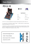
1A M205 Fuse
AC Input
Battery
Output to Load
PS13-1E
Designed & Manufactured
Installation Notes:
•
Always select a clean. dry environment for installation.
•
PS13-1E may be installed using self adhesive stand-offs - ensure surface is clean before mounting
•
Ensure adequate free air circulation around circuit board to avoid over-heating.
•
If fuse requires replacement, determine cause of failure and replace only with M205 F 1A/250V.
•
Onboard Battery Charger can provide up to 90 mA - remember to consider this current when determining
overall system current draw.
•
Battery charge current (90 mA) should be subtracted from total power supply output (1A) to allow a
discharged battery to be recharged after extended AC power outage