1
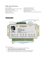
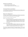
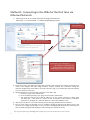
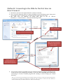
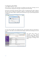
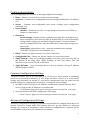
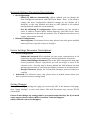
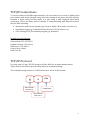
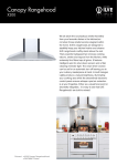
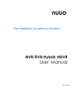
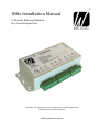
IN8e Installation Manual 8-Channel Ethernet Enabled Dry Contact Input Unit The IN8e is a simple low cost 8-channel dry contact input unit, with Ethernet communications whitecreations.com.au White Creations Input Unit Range IN8s IN8e 8 Channel Low Cost Dry Contact Input Unit with RS-232 communications 8 Channel Low Cost Dry Contact Input Unit with Ethernet communications Disclaimer & Conditions of Use: White Creations Input Unit products are not intended for use where there may be any risk to persons or property. White Creations will not be held liable for any injury or damage to property caused by our products. You must use White Creations products only in non-crucial (or “convenience”) elements of a system - where a failure may inconvenience the user, but not directly or indirectly cause damage to any property or injury to any persons. Do Not Open Device! No User Serviceable Parts inside. Opening the device for any reason will void any warranties. For technical support or product faults please contact whitecreations.com.au/techsupport This manual is subject to change without notice; the latest version is available at whitecreations.com.au/manuals 2 Contents Low Cost Input Unit Features 4 IN8e Specifications 5 Hardware Installation 7 Testing Hardware Installation 7 Ethernet Configuration 7 TCP/IP Connections 13 TCP/IP Protocol 13 Remote Control and Port Forwarding 15 Contact White Creations General Enquiry: Technical Support: Place an order: Product Manuals: whitecreations.com.au/enquiry whitecreations.com.au/techsupport whitecreations.com.au/order whitecreations.com.au/manuals 3 Low Cost Input Unit Features Our Low Cost Input Unit has been developed with the installer in mind. We have tried to make it really easy for installers to install, and programmers to integrate with. We have also tried to provide this at the lowest possible price. For Installers: Quality pluggable screw terminal connectors - easy to install, replace, debug, and fault-find LED indicators for status of each input For Programmers: Easy ASCII string to receive input state Simple ‘No Frills’ control – the unit sends a status string on a state change for each input, or poll the device for input status Easily configure Ethernet models by connecting to it through a web browser For Everyone: Well priced Very reliable Great Australian support Please note: Units are not shipped with 12V Power Supply 4 Multiple units can operate from a single 12V power supply, so instead of providing one with each unit, you can install them as needed. Please make sure the power supply has a sufficient current rating, taking other equipment into account if applicable. For example, the IN8e requires 100mA, so a 1000mA power supply can power up to 10 units. IN8e Specifications Input channels: 8 Input terminals: 8x Dry Contact Input Contacts Control: Ethernet TCP/IP Default IP Address: 192.168.1.222 Default port: 10001 Max Ambient Temp: 40⁰C Input output rating: 30V, 3A Operating Voltage: 12V DC Operating Current: 100mA max Physical Dimensions: 146mm x 91mm x 40mm (including connectors) IN8e Top View Ethernet Power LED 12VDC Supply Channel Status LEDs Dry Contact Input Terminals Channels 1-8 Hardware Interfaces: Power LED: Indicates the unit is powered on and working Ethernet: RJ45 connection to Ethernet network 12V DC Supply: DC power supply input terminals Channel Status LEDs: Indicate the current status of each input channel Dry Contact Input Terminals: connection for each dry contact input 5 6 Hardware Installation 1. Mount IN8e firmly in a dry indoor climate 2. Wire input terminals to desired control devices 3. Wire power supply and connect device to Ethernet network Testing Hardware Installation You can easily test your installation by powering up the device and toggling each dry contact input. When any input is closed its Channel Status LED will be on, and when it is open its Channel Status LED will be off. Ethernet Configuration The Ethernet settings of the IN8e are configured by its configuration web page. There are 2 ways to connect to the IN8e for the first time. Below is a quick overview of the 2 methods, and there are detailed procedures on the following pages. Methods for connecting to the IN8e for the first time: Method 1: Connect via Ethernet Network If your PC is on a network in the range 192.168.1.xxx and there is no device at 192.168.1.222, then you can plug the IN8e into the network, and open its configuration web page by typing its IP address into a web browser. If your PC network is not in that range, you will first have to connect via Direct Connect, and change the IP configuration of the IN8e to be in the range of your network Method 2: Connect via Direct Connect You can directly connect by plugging the IN8e directly to your PC with a crossover Ethernet cable. You will need to assign a static IP address to your computer in the 192.168.1.xxx range, and then you can open the IN8e configuration web page by typing its IP address into a web browser Once your PC is on the same network and in the same IP range as the IN8e, you can access the IN8e configuration web page (see Configuring the IN8e), or you can start communicating with the device by connecting to it with a terminal program (see TCP/IP Protocol). 7 Method 1: Connecting to the IN8e for the first time via Ethernet Network 1. Check if your PC is on a network in the IP range 192.168.1.xxx Click Start >> Control Panel >> Network and Sharing Center Click “Details” Workstation Shows this window Click “Wireless Network Connection” Check that your settings are: IP address is 192.168.1.xxx Subnet mask is 255.255.255.0 Default gateway is 192.168.1.xxx 2. If your PC is in the 192.168.1.xxx range, then proceed to the next step. If not then you may have to connect and configure the IN8e using the Direct Connect method. You could then change the network configuration of the IN8e to be in the same IP range as your Ethernet network and then you can connect to it this way 3. Check that there is no network device present at 192.168.1.222 a. Click Start, type “cmd” and hit enter b. In the command prompt, type “ping 192.168.1.222” and hit enter c. The response will tell you if this IP address is in use. (if the response is “Reply from 192.168.1.222…” then there is a device at that IP address, if the response is “Request timed out” or “Reply from < other IP address>”, then the IP address is free 4. Disconnect any device at 192.168.1.222 if present, then plug the IN8e into the network 5. You can now connect to the IN8e. You can configure settings by typing its IP address into a web browser (see Configuring The IN8e), or you can start controlling input channels by connecting to it with a terminal program and sending it control strings (see TCP/IP Protocol) Tip: Using smartphone apps like Fing make it really easy to scan the IP addresses on your network 8 Method 2: Connecting to the IN8e for the first time via Direct Connect 1. Disconnect your PC from any hardwired or wireless networks 2. Use a crossover Ethernet cable to connect the IN8e to your PC Ethernet port, then power up the IN8e. (note: on modern PC’s a straight through cable may also work) 3. Set your PC’s IP address to static and give it an IP address Click Start >> Control Panel >> Network and Sharing Center Workstation Shows this window Click “Properties” Click “Local Area Connection” Select “Use the following IP address” then fill out these details Shows this window Select “Internet Protocol Version 4” Then click “Properties” When done, Click “OK” for both Windows 4. You can now connect to the IN8e. You can configure settings by typing its IP address into a web browser (see Configuring The IN8e), or you can start controlling input channels by connecting to it with a terminal program and sending it control strings (see TCP/IP Protocol) Note: to re-connect to your existing wired or wireless network, you need to restore your PCs IP settings back to what they were, usually you would have to follow the same procedure as above, but select “Obtain IP address automatically” and “Obtain DNS server address automatically” 9 Configuring the IN8e Once your PC is on the same network as the IN8e and in the same IP range, you can access the IN8e configuration web page to change the network settings. Open your web browser (internet explorer, safari, etc) and type in the IN8e IP address into the browser address bar (default IP address is 192.168.1.222). When prompted, enter the user name “admin” and the password and click “Log In” (the default password is <blank> ). You now have the IN8e web configuration page, which appears like this. (The Ethernet processor of the IN8e is the Lantronix XPort chipset, hence their branding on the web page). The home page shows an overview of the current network settings, while the left hand pane navigates through all the pages of settings of the IN8e. 10 Configuration Settings The following pages are available containing configuration settings: Home – Shows an overview of current network settings Network – Contains user-configurable network settings (DHCP/Static, IP Address, etc) Server – Contains user-configurable web server settings (web configuration password, etc.) Serial Tunnel - Hostlist – Advanced use only – for specifying host devices for the IN8e to initiate a connection to Channel 1 - Serial Settings: Contains factory-configured settings. Do not change any of these settings as it will cause the IN8e to malfunction. If you do accidentally change these settings, you should hit “Apply Defaults” to restore them to factory configuration. Please note that this will reset any other changes you have made - Connection: advanced use only – network communication settings (TCP/UDP, Client/Server, port number, etc.) Email – Future use, please contact us if you’re interested Configurable Pins – Future use, please contact us if you’re interested Apply Settings – Once you’ve changed settings on a page, you need to hit “OK” at the bottom of the page, then “Apply Settings” to save and reboot. This will disconnect any current TCP/IP connections Apply Defaults – Sets all settings back to factory defaults, except IP Address which changes to DHCP Common Configuration Settings The most common way to use the IN8e is as a TCP server, which means it continually waits for an incoming connection. A TCP client will then connect to it, send control strings, and disconnect as needed. To run in this configuration you can either use the default settings (no configuration necessary), or configure these settings: Set IN8e to DHCP or Static, set IP address, subnet mask, Default Gateway, DNS Server. Using a static IP address is recommended - In “Network” page (See Network Settings Parameter Descriptions –next page ) Set a password for the IN8e configuration web pages - In the “Server” page (See Server Settings Parameter Descriptions –next page) Advanced Configuration Settings Advanced configuration settings are available but shouldn’t be changed unless there is a specific reason to change them. This manual does not go into details for advanced settings. If you have an installation where advanced configuration is required, please contact White Creations for the advanced user manual. 11 Network Settings Parameter Descriptions IP Configuration: - Obtain IP Address Automatically: When enabled, you can change the Auto Configuration Methods, and DHCP Host Name. Note: If you need to change the Auto Configuration Method settings do not disable all 3 methods, as the only method will then be ARP (default is all enabled, leaving them all enabled is recommended) - Use the following IP configuration: When enabled, you can specify a static IP address, Subnet Mask, Default Gateway, and DNS Server. Enter these parameters in decimal-dot notation. The IP Address must be set to a unique value on the network Ethernet Configuration: - Auto Negotiate: For advanced users only, please leave this option enabled unless you have a specific reason to change it Server Settings Parameter Descriptions Server Configuration: - Enhanced Password: When enabled you can create a password up to 16 characters in length, when disabled you will be limited to 4 characters - Telnet/Web Manager Password: This is the IN8e configuration web page access password. Choose a password you will not forget as there is no external reset – the only way to factory default the IN8e without the web manager password is to send it back to White Creations, in South Australia - Retype Password: Retype the Telnet/Web Manager password above to confirm Advanced: For advanced users only, please leave at default values unless you have a specific reason to change them Saving Changes Once you’ve changed settings on a page, you need to hit “OK” at the bottom of the page, then “Apply Settings” to save and reboot. This will disconnect any current TCP/IP connections. Please do not change any settings unless you understand what they do. If you need some support please contact White Creations Technical Support: whitecreations.com.au/techsupport 12 TCP/IP Connections To receive status of the IN8e input channels, you can connect to it via its IP address and port number, and send it the poll string. On a state change of any input, the IN8e will also transmit a status string for that input, so a poll string is only required upon initial connection. There are many devices capable of communicating with Ethernet devices like the IN8e including: Automation and Control Systems (eg. Crestron, AMX, C-Bus, push, control4, etc) Smartphone apps (eg. Command Fusion iViewer, TCP/IP remote, etc) A PC running a TCP/IP terminal program (eg. Realterm) Default Network Settings IP Address: 192.168.1.222 Subnet Mask: 255.255.255.0 Default Gateway: 192.168.1.1 DNS Server: 192.168.1.1 Control Port: 10001 Web Port: 80 TCP/IP Protocol You may send a 3-byte TCP/IP string to poll the IN8e for its input channel status. There must be an 80ms or greater delay between command strings. The command sting consists of 3 ASCII characters, and is in this format: g s ASCII Character Lower-case “g” <CR> Carriage Return ASCII Character Lower-case “s” 13 Command Table The following shows all available commands you can send to an IN8e input unit. Note that <CR> represents the ASCII character for a carriage return (hex 0D) Available Commands Poll (Get Status Of All Input Channels) String to send to device gs<CR> Response from the IN8e Once a valid poll string has been received by the IN8e, it will respond with the status of all input channels. If the device does not recognize a string, it may return the string “Invalid command”. On a state change of any input, the IN8e will also transmit a status string for that input, so a poll string is only required upon initial connection. The response format is “Input X is open” if the input channel is open, or “Input X is closed” if the input channel is closed, where X is the input channel number. Examples To poll the IN8e (or get status of all input channels), send the string: gs<CR> The IN8e will respond with the current state of each input channel, in the format: Input 1 is open<CR> Input 5 is closed <CR> Input 2 is open <CR> Input 6 is open <CR> Input 3 is closed<CR> Input 7 is closed <CR> Input 4 is open <CR> Input 8 is closed <CR> Once input 1 changes state to closed, it will transmit the string: Input 1 is closed<CR> Once input 6 changes state to open, it will transmit the string: Input 6 is open<CR> 14 Remote Control and Port Forwarding The IN8e can be controlled remotely by setting up port forwarding in the remote site’s internet router. The IT department can open an external port to point to the internal IP address and port of the IN8e. You can then connect to the IN8e through the internet from another location, using the external IP address of the site and the external port assigned to you. Port 80 must be forwarded for access to the configuration web page, and port 10001 must be forwarded to poll input channels. Note: Port 80 and 10001 are the default ports used by the IN8e. If you can’t communicate on these ports, the installer may have changed them. For domestic applications, most decent internet routers will allow port forwarding, but you may need to set up a dyndns (or similar) account to keep track of your external IP address. This manual does not go into specific details as each router is different. You should ‘google’ your router model to find information to set this up. If you need some support, please contact White Creations Technical Support: whitecreations.com.au/techsupport. 15 General Enquiry: Technical Support: Place an order: Product Manuals: 16 whitecreations.com.au/enquiry whitecreations.com.au/techsupport whitecreations.com.au/order whitecreations.com.au/manuals