1
AVer FD2000
User Manual
Table of Contents
PREFACE............................................................................................................................................ 1
PRODUCT FEATURES ....................................................................................................................... 1
SPECIFICATIONS ............................................................................................................................... 2
PACKAGE CONTENTS....................................................................................................................... 4
PRODUCT INSTALLATION................................................................................................................. 5
MONITOR SETTING ........................................................................................................................... 5
HARDWARE INSTALLATION AND I/O PIN ASSIGNMENT ........................................................................... 6
1.
PRODUCT OVERVIEW ................................................................................................................. 6
NETWORK LED AND BUTTON DEFINITION ........................................................................................... 8
2.
INSTALLATION ............................................................................................................................ 8
3.
DISASSEMBLING THE CAMERA .................................................................................................. 11
POWER OVER ETHERNET (POE)...................................................................................................... 14
IP ASSIGNMENT .............................................................................................................................. 15
FINDING IP CAMERA BY USING “NXU LITE RECORDING SOFTWARE” .................................................... 15
FINDING IP CAMERA BY USING “IP INSTALLER”................................................................................... 18
USING DHCP SERVER/ROUTER NETWORK ...................................................................................... 20
USING NON-DHCP SERVER/ROUTER NETWORK ............................................................................. 21
INSTALL ACTIVEX CONTROL ............................................................................................................ 23
USING THE IP CAMERA BROWSER INTERFACE .......................................................................... 25
PREVIEW ....................................................................................................................................... 25
SYSTEM > GENERAL ....................................................................................................................... 27
SYSTEM > GENERAL > MAINTENANCE .............................................................................................. 27
To Upgrade the IP Camera Firmware: ..................................................................................... 28
SYSTEM > GENERAL > DATE & TIME ................................................................................................ 29
SYSTEM> GENERAL > EVENT LOG ................................................................................................... 30
SYSTEM > USER MANAGEMENT ....................................................................................................... 31
SYSTEM > USER MANAGEMENT > ADMIN .......................................................................................... 31
SYSTEM > USER MANAGEMENT > GUEST USER ................................................................................ 32
SYSTEM > NETWORK SETTING > SETTING ........................................................................................ 33
SYSTEM > NETWORK SETTING > RTSP ........................................................................................... 34
SYSTEM > IMAGE ............................................................................................................................ 35
SYSTEM > IMAGE>PREFERENCE ...................................................................................................... 35
SYSTEM > IMAGE > PRIVACY ZONE .................................................................................................. 38
SYSTEM > VIDEO STREAM > PROFILE .............................................................................................. 39
SYSTEM > AUDIO ............................................................................................................................ 40
EVENT > MOTION ........................................................................................................................... 41
STATUS INFORMATION ..................................................................................................................... 42
FACTORY DEFAULT ......................................................................................................................... 43
TROUBLESHOOTING ...................................................................................................................... 44
FCC NOTICE (CLASS B) .................................................................................................................. 45
COPYRIGHT ..................................................................................................................................... 45
NOTICE ............................................................................................................................................. 45
WARNING ......................................................................................................................................... 45
COPYRIGHT ..................................................................................................................................... 46
NOTICE ............................................................................................................................................. 46
WARNING ......................................................................................................................................... 46
LIMITED WARRANTY ....................................................................................................................... 46
GOVERNING LAW AND YOUR RIGHTS .......................................................................................... 47
Preface
The FD2000 is an H.264 2-megapixel; full HD dome camera designed with ultra-discreet,
recessed-mount and super mini dimension (Φ:97mm) for indoor use. With innovative and unique fix
supports, FD2000 is specifically developed for recessed mounting in suspended ceilings (drop
ceilings), offering discreet video surveillance solutions that is ideal for retail stores, boutiques, schools,
banks, elevators and other office buildings. FD2000 can provide superior quality video during the day
without compromising on nighttime performance with its digital day and night function.
Product Features
2M-pixel, full HD Definition (1080p) 30fps support
Ultra compact size and easy installation, specifically for suspended ceilings
Digital Day and Night
Wide Dynamic Range
Noise reduction
Enhanced Backlight Compensation up to 6 selectable areas
Adjustable Shutter Speed
Power over Ethernet (PoE)
H.264/MJPEG compression formats
Android/iOS mobile phone/PDA support
Free bundled AVer NXU Lite recording software
1
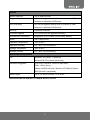
Specifications
Hardware
RAM
256MB
Flash
256MB
Image Sensor
1/3” CMOS (2 megapixels)
Lens Type
Fixed lens, f=3.4mm
Electric Shutter
1/25~ 1/8192 sec (PAL); 1/30~ 1/8192 sec (NTSC)
I/O
N/A
Video Out
N/A
Audio In
1 (built-in microphone, mono type)
G.711 (64K)
Audio Out
N/A
Power over Ethernet
Yes
Power Consumption
PoE Class 0 (IEEE802.3af): 5.5W
Dimensions
Ø : 97 x 104.5 H (mm)
Weight
380g
This unit operates with PoE as power supply only.
Network
Ethernet
Network Protocol
Ethernet (10/100 Base-T), RJ45 connector
IPv4, HTTP, TCP, RTSP/RTCP/RTP, ICMP, UDP, IGMP,
DNS, DHCP, ARP, NTP
System
Video Resolution
Video Adjust
1080p(1920x1080), 720p(1280x720), VGA(640x480),
CIF(352x240), QVGA(320x240)
Brightness, Contrast, Saturation, Sharpness, Shutter
Speed, Day-Night Mode, WDR, Backlight Compensation.
Triple Streaming
Yes
Image Snapshot
Yes
Full Screen Monitoring
Yes
Privacy Mask
Yes,4 different areas
Compression Format
H.264/ MJPEG
Video Bitrates Adjust
Yes (CBR/VBR)
2
System
Motion Detection
Yes, 4 different areas
Triggered Action
N/A. All the triggered actions have to be done on VMS
Pre/ Post Alarm
N/A. All the triggered actions have to be done on VMS
Security
Password Protection
Firmware Upgrade
HTTP mode (can be upgraded remotely)
Simultaneous Connection
Suggestion up to 6 clients (H.264,1080p, 8Mbps)
Audio
Yes, 1-way (mono)
Operation Temperature
-10°C to 50°C
Operation Humidity
0% ~ 90%, non-condensing
Storage Temperature
-20°C to 60°C
Storage Humidity
0% ~ 90%, non-condensing
software or standalone NVR device.
software or standalone NVR device.
Web browsing requirement
OS
Windows® XP (32-bit), 7 (32/64-bit)
Microsoft® IE 9.0 or above (32-bit only)
Hardware Suggested
CPU: Intel® Pentium 4 2.4GHz or equivalent
RAM: 1 GB or above
Display: NVIDIA GeForce 6 Series or ATI Mobility Radeon
9500 (DirectX 9 compatible)
Mobil support
iOS 4.3 or above, Android 1.6 or above.
*SPECIFICATIONS ARE SUBJECT TO CHANGE WITHOUT NOTICE.
3
Package contents
Item
Descriptions
1. FD2000
2. CD (User’s Manual and Quick Guide included)
3. Mounting template label
*This model doesn’t support power adapter and only supports PoE power.
4
Product Installation
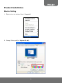
Monitor Setting
1. Right-click on the desktop. Select “ Properties”
2. Change “Color quality” to “Highest (32-bit)”.
5
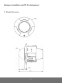
Hardware Installation and I/O Pin Assignment
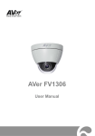
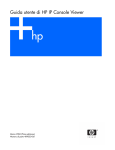
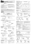
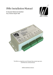
1. Product Overview
6
Definition:
Index #
1
2
3
Name
Bracket
Body
Top Case
7
Network LED and Button Definition
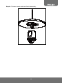
2. Installation
Step 1:
Use the mounting template label to mark-out and prepare the mounting area.
Drill a round hole with Ø84 ㎜ in diameter in the ceiling.
Put network cable through the round hole on the ceiling, and then attach to the camera
body.
Put camera into the round hole on the ceiling. Please hold the camera body to avoid
falling.
8
Step 2:
Use a screwdriver to swivel three screws to bring out three locking arms.
Tighten the screws sufficiently to compress the arms to adjust to mounting surface.
[Notes] The clip design is suitable for the suspended ceiling less than 25.5mm in thickness
Locking arm
Step 3: Then adjust the tilt angle screw to shoot the suitable scenery
9
Step 4: Attach the camera housing with extra care on direction.
Step 5: Fasten the camera by screwing cover to the pedestal with screws and complete
installation.
10
3. Disassembling the Camera
Step 1: Loosen the screws on the cover.
Step 2: Remove the camera housing
11
Step 3:
Pull down the camera while the bracket is still attached to the ceiling.
Move the two fasteners to take out the camera body. (Two of three applicable fasteners in
total can be forced to move).
Take off the camera body while the bracket is still attached to the ceiling.
12
Step 4:
:Pull down network cable and finish disassembly.
13
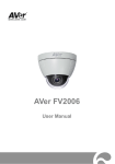
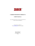
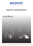
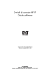
Power Over Ethernet (PoE)
Set up the IP camera through Power over Ethernet (PoE). PoE is a technology that integrates power
into a standard LAN infrastructure. It enables power to be provided to the network device, such as an
IP camera, using the same cable as that used for network connection. It eliminates the need for power
outlets at the camera locations.
[Note] 802.3at, 30W PoE Switch is recommended.
[Note] PoE switch compatible list: D-Link DES-1316/
ZyXEL ES-2024/D-Link-1005A/A5-20S4B/WS-C3560X-24P-L/VD2
PoE IP Camera
Ethernet
PoE Switch
Power
Ethernet Cable
PoE IP Camera
14
IP Assignment
There are two ways to find IP Camera:
−
Finding IP Camera by using “NXU Lite recording software”
−
Finding IP Camera by using “AVer IPCam Utility”
Finding IP Camera by using “NXU Lite recording software”
1. The NXU Lite software is in the attached software CD. Before launching it, please install the
software first. During the installing process, users will be required to input a User name and
Password for login NXU Lite system. Users can define the User name and Password as wishes.
Please refer to NXU Lite user manual for detailed installation instruction.
2. To run the application, double-click
on your PC desktop or click Start > Programs > DVR >
NXU Lite. For security purpose, some of the features would require you to enter User name and
Password before it can be accessed. When the Authorization dialog box appears, key in your User
ID and Password. (If this is the first time, enter the one you have registered when installing the
software.
Click it to call out virtual
keyboard.
15
3. Click “Setup” button.
4. Click “Add IPCam” button.
5. Select “IP Camera” item.
16
6. Key in IP Camera’s ID and Password (default is admin/admin) and click “Auto Search” to find
camera.
7. In Search Result window, click it the IP camera model that user has purchased (Please ignore
ONVIF connection item); the camera is in red text that is configurable. User can double-click on
the camera is in red text and configure the IP camera’s setting; even the IP camera is not in the
same IP segment. Press “OK” to back to previous screen and press “Connect” to start live view.
Double-click the IP camera model
that user has purchased (ex:
FD2000).
Please ignore ONVIF
protocol selection; NXU Lite
doesn’t support ONVIF
connection.
17
Finding IP Camera by using “AVer IPCam Utility”
1. Use the software, “AVer IPCam Utility” to assign the IP address of the IP camera. The software is
in the attached software CD.
2. Run the IPCam Utility
3. Select the proper network adapter and click [Search] to begin searching.
4. Select and double click the IP camera you want to access. If you want to change the setting of the
selected IP camera, enter the user ID, correct password, and change the settings and then click
[Apply]. This will change the setting and rescan the network again.
[Notes]: The default Gateway number is 0.0.0.0. Users can change Gateway number only
when choosing Static IP
18
The IE browser will open and direct you to IP camera login page. This requires IPViewer.ocx to run.
If the IE ActiveX warning message appears, click to allow running the add-on.
[Note]
The default IP address is: 192.168.1.168
The default ID and Password are both ”admin”.
It is not allowed to enter device name in Chinese and any other special characters (' " \ & ^).
Gateway number can’t be “0”.
IP camera device name should be less than 30 digits
19
Using DHCP Server/Router Network
To use DHCP, please change the setting on the IE: IE configuration network setting enable
DHCP function Apply.
After finishing the setting, please use AVer IPCam Utility to find IP Camera.
20
Using NON-DHCP Server/Router Network
In Non-DHCP server/router network, the static IP address must be assigned to the device each time
when adding another IP camera to the network; the default IP address of the current one must be
changed to avoid conflict.
Please make sure the Subnet of the PC’s IP address and the IP camera’s IP address are the same.
[Example]
The same Subnet:
IP camera IP address: 192.168.1.168
PC IP address: 192.168.1.100
Different Subnets:
IP camera IP address: 192.168.1.168
PC IP address: 192.168.2.100
To Change PC IP Address:
Control PanelNetwork Connections Local Area Connection Properties Internet
Protocol (TCP/IP) Properties
Please make sure your IP camera and PC have the same Subnet. If not, please change IP
camera subnet or PC IP subnet accordingly.
PC’s IP address:
21
IP camera IP addresses:
A quick way to access remote monitoring is to double-click on a selected IP camera in “Camera
Name list” in AVer IPCam Utility. Then, the IE browser will open and connect to IP camera.
[Notes]: The default Gateway number is 0.0.0.0. Users can change Gateway number only
when choosing Static IP.
5. Then, please key in the default “ID” and “Password”, both of which are “admin”.
22
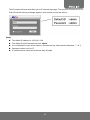
Install ActiveX Control
The first time you attempt to view the camera video via Internet Explorer, it will ask you to install the
ActiveX component.
If the installation fails, please check the security settings for the Internet Explorer browser.
1. IE Tools Internet Options… Security Tab Custom Level… Security Settings Download unsigned ActiveX controls Select “Enable” or Prompt.
2. IE Tools Internet Options… Security Tab Custom Level… Initialize and script ActiveX
controls not marked as safe Select “Enable” or Prompt.
1
2
3
4
23
5
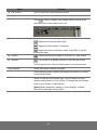
When the following dialogue box appears, click “Yes”.
24
Using the IP Camera Browser Interface
The admin have the full access to the IP Camera browser interface. The menu on the left, you can
expand and navigate to access all the features.
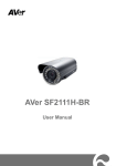
Preview
Launch the Internet Explorer browser, type the IP address of the IP camera in the address field. It will
show the following dialogue box. Key-in the ”ID” and “Password”. The default”ID” and “Password” are
both “admin”.
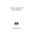
Once connected to the IP camera, the following program interface will appear.
Name
Function
(1) System/Event/Status
Information
Set up IP camera’s configuration.
(2) Login IP
Show PC’s IP address
(3) Bandwidth
Show current IP camera’s transmitting bandwidth
25
Name
Function
(4) FW Version
Show IP camera’s current firmware version
(5) Logout
Exit the application
(6) Stream status display
Press
button to display video stream status, such as codec
and frame rate. Press it again to turn off.
(7) Video screen
Change the video screen display.
Display the actual video pixel size
Display the video screen in fixed size.
Display the video in full screen mode. Press ESC to exit full
screen mode.
(8) Capture
Capture and save the image on the screen in *.bmp format
(9) Speaker
Turn on the PC’s speaker so that PC side can hear sound
from IP camera side. Click this button again to mute this function.
(10) Language
Select the browser interface language.
(11) Motion detection
While detecting motion objects, the triangle icon shows up. Press it
to release the notice.
(12) Stream
Switch to view the video stream type. The IP camera can send
multiple video streams of up to 3 types. To change the video stream
setting, go to System > Video Stream.
[Notes] When streaming 2 setting in “Video Setting” is closed,
there won’t have other stream option
26
System > General
In this section, only admin level is authorized to configure the IP camera system maintenance and the
date and time settings.
System > General > Maintenance
In the Maintenance tab, the administrator can upgrade the system firmware; reset the configuration
settings, reboot, and restore all back to factory default settings.
Name
Function
(1)
Video System
Select the video format.
(2)
Import Configuration
Settings
settings file from the computer hard disk to IP camera.
Download to replace the current settings with the configuration
(3)
Export Configuration
Settings
computer hard disk.
(4)
Set to Factory Default
Set all the configuration settings back to default.
Upload to save all the configuration settings from the IP camera to
27
Name
(5)
Network Camera
Reboot
(6)
Firmware Upgrade
Function
Turn the IP camera off and on again.
Upgrade the firmware to the latest version. All camera motions will shut
down during firmware update. Close any other screens before starting a
firmware update. Never disconnect power and LAN cable during the
firmware update process, or an update failure will occur and
maintenance will be required. Rebooting the unit after firmware update
may take approximately 3 minutes.
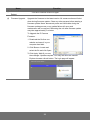
To Upgrade the IP Camera
Firmware:
1. Download the file from our
website and save it in your
computer hard disk.
2. Click Browse. Locate and
select the file and click Open.
3. Click Apply. Wait till you see
the massage “Update complete” You may now click the Internet
Explorer browser refresh button. The login page will appear.
28
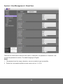
System > General > Date & Time
In the “Date & Time” tab, the administrator can set and update the system’s date and time. After filling
in the correct settings, click Apply to apply the new settings.
Name
(1) Synchronization Mode
Function
Select the date & time settings method.
Manual – Manually set the date and time.
Sync with NTP Server – Obtain the date and time setting from
NTP server. Key in the NTP server name.
Sync from PC – Obtain the date and time setting on the current
login computer.
(2) Date & Time manual
setting
(3) NTP Server
When choosing “Manual” time setting, please set the date and
time here.
When choosing “NTP” time setting, please set the date here.
Time Zone: To select the time zone where the unit is located.
NTP Server: To state the address of NTP server to synchronize
date and time with the unit when If “NTP” is selected in the
Synchronization Mode.
Time Adjustment Period: To select the interval to calibrate the
time of the unit.
Save &Test: To save and test NTP server settings
(4) Daylight saving
Check the ON/OFF box to enable or disable Daylight Saving to
enable and setup the start date and end date for daylight saving
29
Name
Function
time. (effective in NTP mode only)
System> General > Event Log
In this section, it displays the IP camera system event log.
30
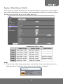
System > User Management
In this section, only admin level is authorized to create, delete, and edit the account in Account tab and
configure the client connection setting in Connection tab.
System > User Management > Admin
IP camera supports two different user accounts – Administrator (Admin) and Guest User.
User Type
Access Rights
Admin
Can access all the configuration pages
Guest User
Can only access the preview and status information pages.
31
System > User Management > Guest User
There are five Guest Users. Enter the user name in “Username”, the password in “Password”, and
re-enter the password to confirm. The default language is English.
[Note]
1. The password can’t be empty, otherwise, user are not able to login successfully.
2. Please don’t use special symbols as user name such as *, %, $, &.
32
System > Network Setting > Setting
Device Name: Key in the preferred device name to rename it. Default name is “ipcam”.
Network Type: IP camera supports DHCP, static IP. Click Apply to save the configuration.
−
DHCP: Using DHCP, please choose “ON” to enable it and IP camera will get all the network
parameters from DHCP server automatically.
−
Static IP: Please choose “OFF” on DHCP item so that the IP camera will use static IP setting.
Please enter the IP address, subnet mask, gateway, Primary DNS, and Secondary DNS.
33
System > Network Setting > RTSP
Users can set RTSP port here.
1. RTSP URLs for Stream 1, Stream 2 and Stream3 are: rtsp://(ip address):(RTSP port)/stream1,
rtsp://(ip address):(RTSP port)/stream2, rtsp://(ip address): (RTSP port)/stream3, respectively.
2. RTSP default ID/Password: rtsp/1234. If users set the ID the same as login ID, the password has
to be the same as login in password.
34
System > Image
There are 2 tabs: Preference and Privacy Mask.
System > Image>Preference
In Preference tab, you can adjust the IP camera image parameters, change the video orientation, and
adjust the enhanced functions, such as Shutter Speed, Day-Night and D-WDR.
Exposure:
Auto Exposure: Automatic Exposure controls the light intensity of picture. Users can select
Manual or AES (Automatic Electronic Shutter) for the unit depending on applications. When
choose the Manual, Shutter Speed and Manual Gain can be adjusted
Day-Night: Only when Automatic Exposure set to Manual can this function be adjusted. To set
DAY/NIGHT function, simply move the cursor to select Auto, Color, or BW mode. If Color selected,
the unit is forced to stay in COLOR mode all day. If BW selected, the unit is forced to stay in
NIGHT mode all day.
Shutter Speed: Only when Automatic Exposure set to Manual can this function be adjusted. Set
desired Shutter Speed from 1/30s to 1/8192s. The IP camera will adjust the aperture according to
the amount of outside light.
35
Sense up: Sense up can be enabled if the sensitivity is still not good enough under “High” gain
condition at dark. Optimal image level can be maintained by appropriate gain and shutter
combination that determined automatically inside the unit system. Sense up can be selected from
OFF, 1/30, 1/15, and 1/7.5. As Sense up activates, the exposure time becomes longer and frame
rate becomes smaller, and moving objects may result in blurred images.
Manual Gain: Only when Automatic Exposure set to Manual can Shutter Speed be adjusted. The
value of Manual Gain can be set from 6 to 30dB as an increment of 6. This function applies to
manual lens only.
AGC Maximum: As an adaptive system found in many electronic devices, the average output
signal level is fed back to adjust the gain to an appropriate level for a range of input signal levels.
Denoise: Noise reduction is the process of removing noise from signal. Users can configure the
noise reduction related setting to manipulate noise on the screen.
Image Color:
Users can adjust Brightness, Contrast, Saturation, Hue, AWB, R/G/B Gain, Sharpness, Backlight
Compensation and D-WDR functions.
R/G/B Gain: This function is able to reduce the contrast in the view to set manual gain value of R
Gain, G Gain, & B Gain from level 0 to 255. The red (R) gain is used to adjust the color red in the
viewing image. It allows adjusting red gain manually according to user requirement ranging from
level 0 to 255. The green (G) gain is used to adjust the color of green in the viewing image. It
allows adjusting green gain manually according to user requirement ranging from level to 255. The
blue (B) gain is used to adjust the color of blue in the viewing image. It allows adjusting blue gain
manually according to user requirement ranging from level 0 to 255.
Sharpness: Increasing the sharpness value will sharpen the edges and small feature of viewing
images. If the edges appear too smooth or blurred, increase the sharpness; otherwise, decrease
the sharpness. Sharpness value can be set from 1 to 15.
Backlight Compensation: Set an area for Backlight Compensation. Backlight Compensation is a
function that achieves the brightness of a selected area to optimal image level. This function is
necessary when an auto iris lens tends to close due to an intense light coming from back of object
in the area wished to view so that the area is too dark and difficult to see. In this case, users may
set the area correspond to the portion wished to see. The area size illustrations are roughly as
follows:
36
WDR: This function to provide clear images even under back light circumstances where intensity of
illumination can vary excessively namely when there are both very bright and very dark areas
simultaneously in the field of view of the unit. WDR enables capturing and displaying of both bright and
dark areas in the same frame in a way that there are details in both areas, i.e. bright areas are not
saturated, and dark areas are not too dark.
Picture:
Picture Flip: Set image to be upside or down. Select ON or OFF to activate or deactivate the flip
function.
Picture Mirror: Set image to be left or right. Select ON or OFF to activate or deactivate the mirror
function.
37
System > Image > Privacy Zone
For the security purpose, there are four areas can be setup for privacy mask. Click “Set Privacy
Zone” button first and drag an area on the image screen. Then, click Apply button to save the setting.
Please set up these four privacy zones one by one.
38
System > Video Stream > Profile
There are up to six profiles to choose from. The one that users are using will be in Current Profile. In
each profile, parameters are all configurable including Image Mode, Resolution, Frame Rate, Bit Rate,
Bit Rate Control, and GOP. Be sure to click Apply when done.
[Note]
1. To get the best mobile viewing quality, please download AVer iViewer (AndroidViewer) from the
Apple App store or Google Play. iViewer takes video from Stream 1 or Stream 2.
39
System > Audio
FD2000 supports 1-way audio (mono). User can send audio from IP camera built-in MIC to remote
site.
a. IP Camera to PC: select “ON” to start this function.
b. Select audio input level among High, Mid, and Low for sound input level.
c. In live video screen, click
button to turn on or off
40
the speaker of PC.
Event > Motion
This function is designed to trigger a video recording when the unit detects a motion.
Motion Detection: Set “ON” to turn on motion detection and set motion sensitivity and area.
Sensitivity: Choose different levels of 1~100 for sensitivity. “100”: Motion is activated with slight
changes in brightness or motion. “1”: Motion is activated with big changes in brightness or
motion.
Object Size: Choose different levels of 1~100 for object size. Set the percentage area size for a
recognizable object. “100”: Very large objects trigger motion. “30”: Small objects trigger motion.
Set Motion Area: Set the area you want to trigger motion detection. The motion setup screen will
be opened for selecting the detection area by clicking/dragging the mouse.
41
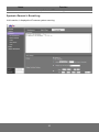
Status Information
Networking Info: Displays network information of the IP camera.
Product Info: Displays product information of IP camera.
.
42
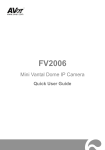
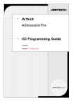
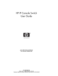
Factory Default
1. Beside Ethernet jack, find the default hole at left side.
2. Press and hold for 5 seconds to return to factory default.
3. To reboot system, press reset hole for 5 seconds.
4. When it goes back to default setting, the default gateway is 0.0.0.0. Please change the setting in IP
finder utility from DHCP to Static IP and then modify the gateway number so that the IP finder utility
can find the IP camera successfully.
Default
Reset
43
Troubleshooting
Here are some useful tips on how to solve some common problems.
Problem
Solution
I forgot the account and password for
Please refer to the manual of “Factory Default setting”
FD2000. How can I go back to default
description.
setting?
How can I record video clip from Web
We don’t support recording on IE. Please use the
GUI?
attached free NXU Lite software in CD to record.
I have updated new firmware but the
After finishing firmware update, please clean up the
firmware version on web GUI doesn’t
cookie history.
change to the updated one.
When I reset the FD2000 to default, I
Users can change Gateway number from IP finder
couldn’t change Gateway number from IP
utility only when choosing Static, instead of DHCP.
finder utility.
44
FCC NOTICE (Class B)
This device complies with Part 15 of the FCC Rules. Operation is subject to the following
two conditions: (1) this device may not cause harmful interference, and (2) this device
must accept any interference received, including interference that may cause undesired
operation.
Federal Communications Commission Statement
NOTE- This equipment has been tested and found to comply with the limits for a Class B digital device,
pursuant to Part 15 of the FCC Rules. These limits are designed to provide reasonable protection
against harmful interference in a residential installation. This equipment generates uses and can
radiate radio frequency energy and, if not installed and used in accordance with the instructions, may
cause harmful interference to radio communications. However, there is no guarantee that interference
will not occur in a particular installation. If this equipment does cause harmful interference to radio or
television reception, which can be determined by tuning the equipment off and on, the user is
encouraged to try to correct the interference by one or more of the following measures:
Reorient or relocate the receiving antenna.
Increase the separation between the equipment and receiver.
Connect the equipment into an outlet on a circuit different from that to which the receiver is
connected.
Consult the dealer or an experienced radio/television technician for help.
European Community Compliance Statement (Class B)
This product is herewith confirmed to comply with the requirements set out in the
Council Directives on the Approximation of the laws of the Member States relating to
Electromagnetic Compatibility Directive 2004/108/EC.
COPYRIGHT
© 2012 AVer Information Inc. All rights reserved.
All rights of this object belong to AVer Information Inc. Reproduced or transmitted in any form, or
by any means without the prior written permission of AVer Information Inc. is prohibited. AVer
Information Inc. reserves the rights to modify its products, including their specifications and any
other information stated herein without notice. The official printout of any information shall prevail
should there be any discrepancy between the information contained herein and the information
contained in that printout. “AVer” is a trademark owned by AVer Information Inc. Other
trademarks used herein for description purpose only belong to each of their companies.
NOTICE
SPECIFICATIONS ARE SUBJECT TO CHANGE WITHOUT PRIOR NOTICE. THE
INFORMATION CONTAINED HEREIN IS TO BE CONSIDERED FOR REFERENCE ONLY.
WARNING
TO REDUCE RISK OF FIRE OR ELECTRIC SHOCK, DO NOT EXPOSE THIS APPLIANCE TO
RAIN OR MOISTURE. WARRANTY VOID FOR ANY UNAUTHORIZED PRODUCT
MODIFICATION.
THE MARK OF CROSSED-OUT WHEELED BIN INDICATES THAT THIS
PRODUCT MUST NOT BE DISPOSED OF WITH YOUR OTHER HOUSEHOLD
WASTE. INSTEAD, YOU NEED TO DISPOSE OF THE WASTE EQUIPMENT BY
HANDING IT OVER TO A DESIGNATED COLLECTION POINT FOR THE
RECYCLING OF WASTE ELECTRICAL AND ELECTRONIC EQUIPMENT. FOR
MORE INFORMATION ABOUT WHERE TO DROP OFF YOUR WASTE
EQUIPMENT FOR RECYCLING, PLEASE CONTACT YOUR HOUSEHOLD
WASTE DISPOSAL SERVICE OR THE SHOP WHERE YOU PURCHASED THE
PRODUCT.
45
COPYRIGHT
©2013 AVer Information Inc. All rights reserved.
All rights of this object belong to AVer Information Inc. Reproduced or transmitted in any form or by any
means without the prior written permission of AVer Information Inc. is prohibited. All information or
specifications are subject to change without prior notice. “AVer” is a trademark owned by AVer
Information Inc. Other trademarks used herein for description purpose only belong to each of their
companies.
NOTICE
SPECIFICATIONS ARE SUBJECT TO CHANGE WITHOUT PRIOR NOTICE. THE
INFORMATION CONTAINED HEREIN IS TO BE CONSIDERED FOR REFERENCE ONLY.
WARNING
TO REDUCE RISK OF FIRE OR ELECTRIC SHOCK, DO NOT EXPOSE THIS APPLIANCE TO
RAIN OR MOISTURE. WARRANTY VOID FOR ANY UNAUTHORIZED PRODUCT
MODIFICATION.
Limited Warranty
AVer Information, Inc. (“AVer”) warrants that the applicable product (“Product”) substantially conforms
to AVer’s documentation for the product and that its manufacture and components are free of defects
in material and workmanship under normal use. “You” as used in this agreement means you
individually or the business entity on whose behalf you use or install the product, as applicable. This
limited warranty extends only to You as the original purchaser. Except for the foregoing, the Product is
provided “AS IS.” In no event does AVer warrant that You will be able to operate the Product without
problems or interruptions, or that the Product is suitable for your purposes. Your exclusive remedy
and the entire liability of AVer under this paragraph shall be, at AVer’s option, the repair or replacement
of the Product with the same or a comparable product. This warranty does not apply to (a) any Product
on which the serial number has been defaced, modified, or removed, or (b) cartons, cases, batteries,
cabinets, tapes, or accessories used with this product. This warranty does not apply to any Product
that has suffered damage, deterioration or malfunction due to (a) accident, abuse, misuse, neglect, fire,
water, lightning, or other acts of nature, commercial or industrial use, unauthorized product
modification or failure to follow instructions included with the Product, (b) misapplication of service by
someone other than the manufacturer’s representative, (c) any shipment damages (such claims must
be made with the carrier), or (d) any other causes that do not relate to a Product defect. The Warranty
Period of any repaired or replaced Product shall be the longer of (a) the original Warranty Period or (b)
thirty (30) days from the date of delivery of the repaired or replaced product.
Limitations of Warranty
AVer makes no warranties to any third party. You are responsible for all claims, damages, settlements,
expenses, and attorneys’ fees with respect to claims made against You as a result of Your use or
misuse of the Product. This warranty applies only if the Product is installed, operated, maintained, and
used in accordance with AVer specifications. Specifically, the warranties do not extend to any failure
caused by (i) accident, unusual physical, electrical, or electromagnetic stress, neglect or misuse, (ii)
fluctuations in electrical power beyond AVer specifications, (iii) use of the Product with any accessories
or options not furnished by AVer or its authorized agents, or (iv) installation, alteration, or repair of the
Product by anyone other than AVer or its authorized agents.
46
Disclaimer of Warranty
EXCEPT AS EXPRESSLY PROVIDED OTHERWISE HEREIN AND TO THE MAXIMUM EXTENT
PERMITTED BY APPLICABLE LAW, AVER DISCLAIMS ALL OTHER WARRANTIES WITH
RESPECT TO THE PRODUCT, WHETHER EXPRESS, IMPLIED, STATUTORY OR OTHERWISE,
INCLUDING WITHOUT LIMITATION, SATISFACTORY QUALITY, COURSE OF DEALING, TRADE
USAGE OR PRACTICE OR THE IMPLIED WARRANTIES OF MERCHANTABILITY, FITNESS FOR A
PARTICULAR PURPOSE OR NONINFRINGEMENT OF THIRD PARTY RIGHTS.
Limitation of Liability
IN NO EVENT SHALL AVER BE LIABLE FOR INDIRECT, INCIDENTAL, SPECIAL, EXEMPLARY,
PUNITIVE, OR CONSEQUENTIAL DAMAGES OF ANY NATURE INCLUDING, BUT NOT LIMITED
TO, LOSS OF PROFITS, DATA, REVENUE, PRODUCTION, OR USE, BUSINESS INTERRUPTION,
OR PROCUREMENT OF SUBSTITUTE GOODS OR SERVICES ARISING OUT OF OR IN
CONNECTION WITH THIS LIMITED WARRANTY, OR THE USE OR PERFORMANCE OF ANY
PRODUCT, WHETHER BASED ON CONTRACT OR TORT, INCLUDING NEGLIGENCE, OR ANY
OTHER LEGAL THEORY, EVEN IF AVER HAS ADVISED OF THE POSSIBILITY OF SUCH
DAMAGES.
AVER’S TOTAL, AGGREGATE LIABILITY FOR DAMAGES OF ANY NATURE,
REGARDLESS OF FORM OF ACTION, SHALL IN NO EVENT EXCEED THE AMOUNT PAID BY
YOU TO AVER FOR THE SPECIFIC PRODUCT UPON WHICH LIABILITY IS BASED.
Governing Law and Your Rights
This warranty gives you specific legal rights; You may also have other rights granted under state law.
These rights vary from state to state.
47