1
Tactical Technologies - Australia’s
Premier Security Power Specialist
High Quality Security Products
Designed, Manufactured and
Supported in Australia
w w w. tac - tech.co m .au
5 Butterfield St, Blacktown NSW 2148 Australia
+61 2 8822-1888 Tel
+61 2 8822-1899 Fax
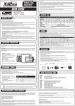
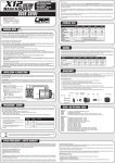
TIM-01 General Features
TIM-01 Layout
A
The TIM-01 Universal Digital Timer
Module has been designed to provide 8
field programmable functions controlling
a Single Pole Double Throw relay with
timing intervals ranging between 1
second and 99 days.
B
C
D
The unit must be powered by a constant
12Vdc power supply and will accept
either positive or negative triggering from
external devices such as reed switches,
request to exit buttons and access control
PLC’s (Programmable Logic Controllers).
E
F
G
TIM-01 may be programmed for Fail Safe
operation (relay is energised when trigger
is not active & will de-energise during
power failure) or Fail Secure (relay does
not change state during a power failure)
®
Universal Digital Timer Module
TIM-01
Programming may be changed whilst
unit is powered, but power must be
disconnected, then reconnected before
changes become active as DIP switch
configuration is read during boot
sequence only.
H
See over page for details
Description
A
B
C
D
E
F
G
H
Power LED
SW 4 - “Ones” Switch Bank
SW 3 - “Tens” Switch Bank
SW 2 - “Timing” Switch Bank
Relay Operation LED
SW 1 - “Mode” Switch Bank
Output Relay - 1A @ 30Vdc Max (SPDT)
Terminal Block
SW 1 = Mode
1
2
3
4
One Shot
-
On
On
Off
Retriggerable
-
On
Off
On
Strobe
-
On
Off
Off
Clutch Relay
-
Off
On
On
Programmed Pulse
-
Off
On
Off
Debounce
-
Off
Off
On
Stand-Off Timer
-
Off
Off
Off
Relay Fail Secure
On
-
-
-
Relay Fail Safe
Off
-
-
-
1
2
3
4
On
On
On
Off
SW 2 = Timing
Seconds
Minutes
On
On
Off
On
Hours
On
Off
On
On
Days
Off
On
On
On
1
2
3
4
0
On
On
On
On
1
On
On
On
Off
2
On
On
Off
On
3
On
On
Off
Off
4
On
Off
On
On
5
On
Off
On
Off
6
On
Off
Off
On
7
On
Off
Off
Off
8
Off
On
On
On
9
Off
On
On
Off
SW 3 = Tens
SW 4 = Ones
1
2
3
4
0
On
On
On
On
1
On
On
On
Off
2
On
On
Off
On
3
On
On
Off
Off
4
On
Off
On
On
5
On
Off
On
Off
6
On
Off
Off
On
7
On
Off
Off
Off
8
Off
On
On
On
9
Off
On
On
Off
TIM-01 Program Modes:
TIM-01 Terminal Connections:
One Shot - Applying trigger activates relay for selected time. Trigger input
must be removed & re-applied to re-activate.
Retriggerable - As for One Shot, except where input is retriggered, the
timer starts again.
Strobe - Requires momentary trigger to be applied, relay will activate for
programmed time.
Clutch Relay - Applying trigger causes relay to change state. Removing
and re-applying trigger forces relay to change state. No timing function in
this mode.
Programmed Pulse - Applying trigger causes relay to operate for
one second at programmed intervals. Set intervals on SW2,SW3 & SW4.
Operation ceases when trigger is removed.
12V +
12Vdc Positive Input
NO
Normally Open Relay
Contact
0V
12Vdc Negative Input
NC
Normally Closed Relay
Contact
Trig -
Negative Trigger Input
( 0V / 12V negative )
NO
Common Relay Contact
Trig +
Positive Trigger Input
( 5-12Vdc positive Max )
Debounce - Applying trigger causes relay to activate for programmed
time. Relay remains activated until timeout regardless of trigger being
removed. If input remains triggered after timeout, relay remains activated
until trigger is removed.
Stand-Off Timer - Ideal for DOTL (Door Open Too Long) alarms. Timing
commences when trigger is applied. If trigger is removed before timeout,
relay will not activate. If trigger remains after timeout, relay will activate. (See
also Note 3. below)
Fail Secure - The relay does not change state during power failure.
Fail Safe - The relay is energised when the trigger is not active. Relay will
de-energise (e.g. releasing power to door locks) during a power failure.
N645
Specifications:
Input Voltage
12Vdc - 13.8Vdc
Quiescent Current
15mA @ 12Vdc
Operational Current
35mA @12Vdc
Relay Rating
1A @ 30Vdc SPDT
Dimensions
85L x 54W x 20H mm
Weight
40g
C-Tick
N-645 to Class B
Important Information:
1.
Power (12Vdc) must be applied constantly to the timer. i.e Power
cannot be applied simultaneously with trigger.
2.
TIM-01 may be programmed while powered, but power must
be disconnected for 10 seconds, then re-applied before new
programming options are initialised.
3.
TIM-01 may be triggered by the application of 0V (12V negative) to
the “Trig - “ terminal or by the application of 5-12Vdc (max) to the
“Trig +” terminal. (Trigger applied singularly, not simultaneously)
4.
Timer is activated by application of trigger - not by removal of trigger
i.e. When using Stand-off Timer mode for DOTL, change-over reed
switches (N.O. when door closed) must be used or a relay used to
invert reed switch operation.
Designed & Manufactured