1
1
4
7
*
2
5
8
0
3
6
9
#
WATERPROOF
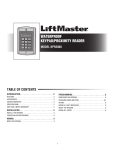
KEYPAD/PROXIMITY READER
MODEL KPR2000
TABLE OF CONTENTS
INTRODUCTION. . . . . . . . . . . . . . . . . . . . . . . . . . . .2
PROGRAMMING . . . . . . . . . . . . . . . . . . . . . . . . . . .5
FEATURES . . . . . . . . . . . . . . . . . . . . . . . . . . . . . . . . . . . . . . . . . . . . . .
ACCESSORIES . . . . . . . . . . . . . . . . . . . . . . . . . . . . . . . . . . . . . . . . . . .
CARTON INVENTORY . . . . . . . . . . . . . . . . . . . . . . . . . . . . . . . . . . . . .
SPECIFICATIONS . . . . . . . . . . . . . . . . . . . . . . . . . . . . . . . . . . . . . . . . .
ONE YEAR LIMITED WARRANTY . . . . . . . . . . . . . . . . . . . . . . . . . . . .
CONFIGURE THE KPR2000. . . . . . . . . . . . . . . . . . . . . . . . . . . . . . . . . . 5
PROGRAM CARDS AND PINS. . . . . . . . . . . . . . . . . . . . . . . . . . . . . . . 6
2
2
2
2
2
ADVANCED PROGRAMMING . . . . . . . . . . . . . . . . . . .7
PANIC CODES . . . . . . . . . . . . . . . . . . . . . . . . . . . . . . . . . . . . . . . . . . .
ALARM. . . . . . . . . . . . . . . . . . . . . . . . . . . . . . . . . . . . . . . . . . . . . . . . .
SOUND & LIGHT INDICATION . . . . . . . . . . . . . . . . . . . . . . . . . . . . . . .
RESET THE KPR2000 . . . . . . . . . . . . . . . . . . . . . . . . . . . . . . . . . . . . .
ERASE ALL CODES . . . . . . . . . . . . . . . . . . . . . . . . . . . . . . . . . . . . . . .
INSTALLATION . . . . . . . . . . . . . . . . . . . . . . . . . . . .3
INSTALL THE KPR2000. . . . . . . . . . . . . . . . . . . . . . . . . . . . . . . . . . . . 3
CHOOSE AN OPERATION MODE. . . . . . . . . . . . . . . . . . . . . . . . . . . . . 3
WIRING . . . . . . . . . . . . . . . . . . . . . . . . . . . . . . . . .4
WIRE THE KPR2000. . . . . . . . . . . . . . . . . . . . . . . . . . . . . . . . . . . . . . . 4
1
7
8
8
8
8
INTRODUCTION
The LiftMaster KPR2000 is a single entry multi-function Access Controller with integrated keypad and card reader. It is designed and manufactured to
perform in a wide range of indoor, outdoor, and harsh environments.
The KPR2000 supports up to 2000 users in multiple access configurations (Card Only, Card or PIN, or Card + PIN). The built in 125 KHz card reader
supports HID 26 bit Wiegand and 30 bit Sentex Wiegand proximity card formats. The KPR2000 offers advanced programming features like; block
enrollment, advanced relay programming, and Panic PINs/Cards (which open the entry and set off the alarm).
Features
Specifications
•
•
•
•
•
•
•
•
•
•
•
•
User Capacity . . . . . . . . . . .2000 Cards/PINS plus 10 Panic Cards/PINS
Operating Voltage . . . . . . . . . . . . . . . . . . . . . . . . . . . . . 12 ~ 24 Vdc
Idle Current . . . . . . . . . . . . . . . . . . . . . . . . . . . . . . . . . . . . . . ~ 50mA
Active Current . . . . . . . . . . . . . . . . . . . . . . . . . . . . . . . . . . . . ~ 80mA
Keypad . . . . . . . . . . . . . . . . . . . . . . . . . . . . . . . . . . . .12 Key (3x4)
Proximity Card Reader . . . . . . . . . . . . . . . . . . . . . . . . . . . HID 26 bit
and 30 bit (Sentex)
Radio Technology . . . . . . 125 KHz Industry Standard Proximity Card
Read Range . . . . . . . . . . . . . . . . . . . . . . . . . . . . . . 1 inch - 2.5 inches
Wiring Connections . . . . . . . . . . . . . . Relay Output, REX, DOTL, Alarm,
Wiegand (in/out)
Relay. . . . . . . . . . . . . . . . . . . . . . . . . . . . . . One (NO, NC, Common)
Adjustable Relay Output Time . . 1 ~ 99 Seconds (5 seconds default)
Adjustable Alarm Output Time . . . . . 0 ~ 3 Minutes (1 minute default)
Lock Output Load . . . . . . . . . . . . . . . . . . . . . . . . . . 1 Amp Maximum
Alarm Output Load. . . . . . . . . . . . . . . . . . . . . . . . . . 1 Amp Maximum
Waterproof (IP68) (meets or exceeds N4)
Vandal Resistant Enclosure
Backlit Keypad
Multi-color LED status display
Integrated Alarm Buzzer & Output
One Programmable Relay Output
Stand Alone or Pass-Through Operation
2000 Users (Card/PIN/Card+PIN)
10 Panic Card/PIN Codes
Low power consumption (50mA)
Anti-Tamper Alarm
Latch Mode to hold door or gate open
Accessories
•
•
•
Model PEDS44 Low Profile Access Pedestal
Model PEDAD 4 x 4 Pedestal Adaptor
Model PS12V2A 12 Vdc, 2 Amp Power Supply
Wiegand Interface . . . HID Wiegand 26 and 30 bit Format Input & Output
Environment . . . . . . . . . . . . . . . . . . . . . . . . . . Meets or exceeds IP68
Operating Temperature . . . . . . . . . . . .-20°C ~ 60°C, or -4°F ~ 140°F
Operating Humidity . . . . . . . . . . . . . . . 10% ~ 90% Non-Condensing
Physical . . . . . . . . . . . . . . . . . . . . . . . . . . . . . . Zinc-Alloy Enclosure
Surface Finish . . . . . . . . . . . . . . . . . . . . . . . . . . . . . . . . .Powder Coat
Dimensions . . . . . . . . . . . . . . . . . . . L:128mm x W:82mm x D:28mm
Unit Weight . . . . . . . . . . . . . . . . . . . . . . . . . . . . . . . . . . . . . . 1 Pound
Shipping Weight . . . . . . . . . . . . . . . . . . . . . . . . . . . . . . . .1.4 Pounds
Carton Inventory
NOT SHOWN: User's Manual
Diode IN4007 (For Relay
circuit protection)
Self Tapping Screws #8 x 1"
One Year Limited Warranty
Manager Add Card
The Chamberlain Group, Inc. warrants to the first consumer purchaser of
this product that it is free from defect in materials and/or workmanship
for a period of 1 year from the date of purchase.
Wall Anchors #6 x 1 1/8"
KPR2000
Keypad/Proximity Reader/Controller
Manager Delete Card
This device complies with Part 15 of the FCC rules. Operation is subject to the
following two conditions: (1) This device may not cause harmful interference,
and (2) this device must accept any interference received, including
interference that may cause undesired operation.
Security Screwdriver
(T-10 Security Torx Driver)
2
INSTALLATION
1
Install the KPR2000.
1 2 3
4 5 6
7 8 9
* 0 #
2
Choose an Operation Mode.
STAND ALONE OPERATION
PASS-THROUGH OPERATION
The KPR2000 functions as a complete access control system. The user
database is stored in non-volatile memory, reads the PINs and card
codes, performs the authentication, and grants and monitors access to
the property or device. In Stand Alone Operation there are three different
Access Configurations listed below:
• Card or PIN (Default): The User must present a valid Wiegand Card to
the KPR2000 or enter their PIN code followed by the # key, in order to
be granted access.
• Card Only: The User must present a valid Wiegand Card to the
KPR2000 in order to be granted access. The facility code and the ID
number are both read and validated as one block of Wiegand data.
• Card + PIN: The User must first present a valid Wiegand Card to the
KPR2000 and then enter their PIN code followed by the # key, in order
to be granted access.
The KPR2000 passes all keypad and card reader Wiegand data to an
external controller. The KPR2000 should be in the “Card or PIN” access
configuration for pass-through operation.
IMPORTANT NOTE: Both modes of operation support Auto User ID
generation (simplest method) and manual entry of user ID.
3
WIRING
3 Wire the KPR2000.
Wire Insulation Color
Wiring Function
Notes
Basic Stand Alone Wiring
Red
Power +
12~24 Volts DC Regulated Power Input
Black
Power -
12~24 Volts DC Regulated Power Input
Pink
Power -
Ground Conductor
Blue
Relay NO
Normally Open Relay Output (Install diode provided)
Purple
Relay Common
Orange
Relay NC
Common Connection for Relay Output
Normally Closed Relay Output (Install diode provided)
Pass-Through Wiring (Wiegand Master and Remote)
Green
Data 0
Wiegand Output (Pass-through)/Input (Stand Alone) Data 0
White
Data 1
Wiegand Output (Pass-through)/Input (Stand Alone) Data 1
Pink
Ground
Advanced Input and Output Features
Yellow
REX
Request To Exit (REX) Input
Gray
Alarm Output
Negative contact for Alarm
Brown
Contact Input
Door/Gate Contact Input (Normally Closed)
WIRING EXAMPLES:
Gate/Door Operator or Fail-Secure Strike
Magnetic Lock or Fail-Safe Strike
Install a 1N4007 or
equivalent diode.
Normally Open
Install a 1N4007 or
equivalent diode.
Normally Closed
KPR2000
KPR2000
Common
External Alarm
Blue
Purple
Red
Gray
Common
External Alarm
Pink
Pink
Black
Black
(1 Amp Maximum)
(1 Amp Maximum)
Networking Two KPR2000 Units or Connecting to an Access Control System
Install a 1N4007 or
equivalent diode.
Normally Open
KPR2000 Stand-Alone
(Master Unit)
Common
External Alarm
Orange
Purple
Red
Gray
KPR2000 Stand-Alone
(Remote Unit)
Blue
Purple
Red
Gray
Red
Black
Black
Pink
Pink
(1 Amp Maximum)
Green (Data 0)
White (Data 1)
Pink (must connect for ground reference)
Maximum of 500 feet (152.4 m)
4
PROGRAMMING
4 Configure the KPR2000.
Change the configure settings according to your application (optional). Multiple configuration settings can be changed at one time: enter
program mode, change desired settings, then exit program mode.
SET MASTER CODE
SET DOOR OPEN TOO LONG (DOTL) ALARM
The 6 digit Master Code is used to prevent unauthorized access to the
system. To interface with the KPR2000, the manager will need a Master
Code (factory default code: 888888). We highly recommend immediate
update and recording of your Master Code.
This setting requires an external sensor input. The alarm output timing
can be set from 1-3 minutes (default is 1 minute). Factory default is OFF.
Programming Step
Programming Step
Keystroke Combination
1. Enter Program Mode
✱ (Master Code) #
2. Update Master Code
0 (New Code) # (New Code) #
3. Exit Program Mode
✱
SET ACCESS CONFIGURATION
There are 3 types of access configurations for the KPR2000:
• Card or PIN (Default): The User must present a valid Wiegand Card to
the KPR2000 or enter their PIN code followed by the # key, in order to
be granted access.
• Card Only: The User must present a valid Wiegand Card to the
KPR2000 in order to be granted access. The facility code and the ID
number are both read and validated as one block of Wiegand data.
• Card + PIN: The User must first present a valid Wiegand Card to the
KPR2000 and then enter their PIN code followed by the # key, in order
to be granted access.
Programming Step
1. Enter Program Mode
✱ (Master Code) #
30#
3. Exit Program Mode
✱
1. Enter Program Mode
✱ (Master Code) #
2. DOTL Alarm OFF
OR
2. DOTL Alarm ON
OR
2. DOTL Output Timing
60#
3. Exit Program Mode
✱
6 1 # (Alarm sounds for 1 minute)
9 (1-3) #
SET STRIKE-OUT ALARM
The strike-out alarm will engage after 10 failed card/PIN attempts. Factory
default is OFF. The strike-out alarm can be set to deny access for 10
minutes after engaging or it can be set to disengage only after entering a
valid master code or card.
Keystroke Combination
2. Card Only
OR
2. Card + PIN
OR
2. Card or PIN
Keystroke Combination
31#
32#
Programming Step
Keystroke Combination
1. Enter Program Mode
✱ (Master Code) #
2. Strike-Out OFF
OR
2. Strike-Out ON
OR
2. Strike-Out ON
7 0 # (Factory default)
3. Exit Program Mode
✱
7 1 # Access will be denied for 10 minutes
7 2 # Enter Master Code or Valid Card to
silence
SET AUDIBLE AND VISUAL RESPONSE
Factory default is ON.
SET RELAY CONFIGURATION
The relay configuration sets the behavior of the output relay on activation.
Programming Step
Keystroke Combination
✱ (Master Code) #
Programming Step
Keystroke Combination
1. Enter Program Mode
1. Enter Program Mode
✱ (Master Code) #
ON = 7 5 #
OFF = 7 4 #
2. Pulse Mode
OR
2. Latch Mode
4 (1-99) # The relay time is 1-99 seconds
(default is 5 seconds)
4 0 # Sets the relay to ON/OFF latch mode
ON = 7 7 #
OFF = 7 6 #
3. Exit Program Mode
✱
2. Control Backlight
OR
2. Control LED
OR
2. Control Sounds
ON = 7 9 #
OFF = 7 8 #
3. Exit Program Mode
✱
SET WIEGAND INPUT/OUTPUT OPTIONS
The KPR2000 offers input and output for industry standard Wiegand
devices (refer to Specifications). Default is HID 26 bit.
Programming Step
Keystroke Combination
1. Enter Program Mode
✱ (Master Code) #
2. Set Wiegand Format
9 (Bit Format) # Bit Format = Valid 2 digit
format (example: 26 or 30)
3. Exit Program Mode
✱
5
PROGRAMMING
5
Program Cards and PINS.
Programming will vary depending on the access configuration. Follow the instructions according to your access configuration.
GENERAL PROGRAMMING INFORMATION
•
User ID Number: Assign a user ID number to the access code in order to keep track of the users of access cards or PINs. The user ID
number can be any number from 1~2000. IMPORTANT: User IDs do not have to be proceeded with any leading zeros. Recording of User ID
is critical. Modifications to user data require either the card or the User ID be available.
• Proximity Card: Any 125 KHz industry standard 26 bit Wiegand Proximity Card.
• Keypad PIN: The PIN can be any 4~8 digits between 0000~99999999 (except 1234 which is reserved for factory testing). IMPORTANT: PINs
less than 1000 must be preceded with leading zeros. PINs greater than 9999 do not require any leading zeros.
ACCESS CONFIGURATION: CARD OR PIN & CARD ONLY
ADD USER CARD(S)
ADD OR DELETE A PIN
Programming Step
Keystroke Combination
Programming Step
Keystroke Combination
1. Enter Program Mode
✱ (Master Code) #
1. Enter Program Mode
✱ (Master Code) #
2. Add Card: Using Auto ID
(Allows KPR2000 to assign
Card to next available User ID
number)
OR
2. Add Card: Select Specific ID
(Allows manager to define a
specific User ID to associate
the card to)
OR
2. Add Card: Block Learn
(Allows manager to add up to
2000 cards to the KPR2000
in a single step †). Takes 2
minutes to program.
1 (Read Card) #
Repeat Step 2 for additional user
cards
2. Add a PIN
Assigns PIN to user ID
number
OR
2. Delete a PIN
Deletes the User ID number
and associated PIN
1 (User ID) # (PIN) #
Repeat Step 2 for additional PINs
3. Exit Program Mode
✱
3. Exit Program Mode
✱
1 (User ID) # (Read Card) #
CHANGE A PIN
5 (User ID) # (The first card
number) # (Card Quantity) #
Card quantity = number of cards to
be enrolled
This operation is executed from outside of Program Mode.
DELETE USER CARD(S)
Programming Step
Keystroke Combination
1. Enter Program Mode
✱ (Master Code) #
2. Delete Card - By User ID
OR
2. Delete Card -By Card
Number
2 (User ID) #
Deleting by User ID number will clear
cards and PINs
2 (Read Card) #
Requires the user card. Deletes ONLY
the card number
2 (Card Number) #
Deletes ONLY the card number †
3. Exit Program Mode
✱
2. Delete Card - By Card
OR
2 (User ID) #
Repeat Step 2 for additional PINs
† BLOCK LEARN DIRECT ENTRY
Format for programming specific Card Numbers: Facility Code + ID
Number (including leading 0’s) Example: FAC- 24, ID- 100 would be
entered as:
26 Bit: 02400100
30 Bit: 002400100
6
Programming Step
Keystroke Combination
1. Change a PIN
✱ (User ID) (Old PIN #) (New PIN #)
(New PIN #)
PROGRAMMING
ACCESS CONFIGURATION: CARD ONLY
USING MANAGER CARDS
Programming Step Keystroke Combination
KPR2000 managers can use manager cards to program user cards into
and out of the system. There are two pre-programmed manager cards
(an Add Card, and a Delete Card) to allow rapid card enrollment. This is a
form of Auto User ID enrollment and is only available in “Card Only”
configuration.
Add a User Card
1. (Read Manager Add Card)
2. (Read User Card)
Repeat Step 2 for additional user cards
3. (Read Manager Add Card)
Delete a User Card
1. (Read Manager Delete Card)
2. (Read User Card)
Repeat Step 2 for additional user cards
3. (Read Manager Delete Card)
ACCESS CONFIGURATION: CARD + PIN
ADD A CARD + PIN USER
CHANGE PIN
Allows card user to update the PIN for their card + PIN User ID. This
operation is executed from outside of Program Mode.
Programming Step
Keystroke Combination
1. Enter Program Mode
✱ (Master Code) #
Programming Step
Keystroke Combination
2. Add a User Card
Assigns card number
to User ID
1 (Read Card) #
OR
1 (User ID) # (Read Card) #
✱ (Read Card) (Old PIN #) (New PIN #)
(New PIN #)
3. Exit Program Mode
✱
1. Change PIN using a
Card
OR
1. Change PIN using PIN
4. Add PIN
✱ (Read Card) (1234#) (New PIN #) (New
PIN #)
This operation is executed from outside of
Program Mode
✱ (User ID) (Old PIN #) (New PIN #) (New
PIN #)
DELETE CARD BY USER ID
Deleting by ID number will clear cards and PINs.
Programming Step
Keystroke Combination
1. Enter Program Mode
✱ (Master Code) #
2. Delete User Card by
User ID
2 (User ID) #
3. Exit Program Mode
✱
ADVANCED PROGRAMMING
Panic Codes
There is a section of the KPR2000 memory set aside specifically for cards and PINs to be used in the instance of an emergency. There are several
rules that guide the use of these cards/PINs:
• Panic Codes activate the relay and the alarm/alarm output.
• Panic Codes use a User ID of 2001~2010 ONLY.
• Panic Codes must be unique. Duplicated Codes act as a normal User Code.
ADD OR DELETE A PANIC PIN
Programming Step
ADD OR DELETE A PANIC CARD
Keystroke Combination
Panic PIN Codes: Add or Delete a PIN
1. Enter Program Mode
✱ (Master Code) #
2. Add a PIN
OR
2. Delete a PIN
8 (User ID Number) # (PIN) #
3. Exit Program Mode
✱
2 (User ID Number) #
7
Programming Step
Keystroke Combination
1. Enter Program Mode
✱ (Master Code) #
2. Add a User Card
OR
2. Delete a User Card
8 (User ID Number) # (Card) #
3. Exit Program Mode
✱
2 (User ID Number) #
ADVANCED PROGRAMMING
Alarm
Reset the KPR2000
TO RESET THE ALARM
This will reset the KPR2000 to the factory default but all card/PIN
information will still be retained. This will also require reprogramming of
the Master Add and Delete Cards. NOTE: This is useful if the original
Master Add and Delete Cards have been lost.
1. Power the KPR2000 down.
2. Press and hold the ✱ button while power is restored to the KPR2000.
3. Release the button and wait until the amber LED shines.
4. Present any 26 bit proximity card or the Manager Add Card (provided)
to the KPR2000. This card is now the Manager Add Card.
5. Present any 26 bit proximity card or the Manager Delete Card
(provided) to the KPR2000. This card is now the Manager Delete
Card.
When the red LED begins to blink, the KPR2000 has been successfully
reset.
Programming Step
Keystroke Combination
To reset the door forced
open warning
(Read valid card)
OR
(Master Code #)
To reset the door open too
long (DOTL) warning
(Read valid card)
OR
(Master Code) #
ANTI-TAMPER ALARM
The KPR2000 uses an optical sensor as the input for its internal alarm. If
the case is opened while the KPR2000 is powered, the alarm will operate.
To silence, enter a valid credential or cycle power.
Erase all Codes
This will delete ALL User data.
1. Enter Program Mode by pressing: ✱ (Master Code) #.
2. Press 2 0000 #.
All configuration data is retained.
Sound & Light Indication
Operation Status
Red LED
Power On
Flashing
Standby
Flashing
Press Keypad
Flashing
Short Single Beep
5 Second Time-out
Flashing
3 Short Beeps
Enter Master Code Entry Mode
ON
Short Single Beep
In Program Mode
ON
Single Flash
Short Single Beep
Entered Single Program Step Successfully
ON
Single Flash
Short Single Beep
Entered Continuous Program Step Successfully
Green LED
Single Flash
ON
Short Single Beep
ON
3 Short Beeps
Flashing
Entry Granted
Sounds
Short Single Beep
Entered Program Step Incorrectly
Exited from Program Mode
Amber LED
Short Single Beep
ON
Short Single Beep
Alarm Mode Engaged
Flashing
Alarm
Pressing ✱ Toggles Standby/Master Code Entry
ON/Flashing
Short Single Beep
FOR TECHNICAL SUPPORT DIAL OUR TOLL FREE NUMBER:
1-800-528-2806
01-36716B
© 2012, The Chamberlain Group Inc.
All Rights Reserved