1
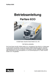
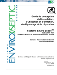
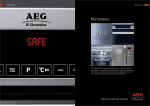
Advanced Enviro-Septic™ (AES)
Wastewater System
Design & Installation Manual
The onsite wastewater system
sweeping the industry
(AES) - Advanced Enviro-Septic Systems Design
and Installation Manual
Preview 2011 RJC
Purpose
The purpose of this manual is to provide guidance in the design and installation
of septic leaching systems using the Presby Environmental, Inc., group of
products.
Presby
Environmental,
Inc., standards
All systems using Advanced Enviro-Septic® products must be designed and
installed in compliance with the procedures and specifications described in this
manual.
State
VWDQGDUGV
Advanced Enviro-Septic® when used as directed meets all the standards for
Domestic use in the subsurface disposal of wastewater.
In this manual
This manual contains the following subjects.
Section
A – Introduction
B – Definitions of Terms
C – Design Criteria
D – Installation, Handling, and Storage Guidelines
E – Sand and Fill Requirements
F – Single Level System Configurations
G – Multi-LevelTM System Configurations
H – Non-Conventional System Configurations
I – Pump System Requirements
J – Venting Requirements
K – Bottom Drain Requirements
L – Simple-Septic® Leaching Systems
M – System Rejuvenation and Expansion
Page
2
4
7
8
11
12
25
30
32
33
35
36
37
Use of
attachment
required
This manual requires the use of an attachment specific to your State or
Province in order to properly design and install Advanced Enviro-Septic® systems.
Technical
support
Action Tanks Industries, provides technical support to all individuals using Presby
Environmental products. For questions about products or the information contained in
this manual, please contact us at 07-54424242
1
Section A
Introduction
Background
Liquid that exits from a septic tank (effluent) contains suspended solids that
can cause other types of septic systems to fail prematurely. Solids can
overload bacteria, cut off aeration required for bacterial activity, and/or seal the
underlying soil.
Our unique
system
components
The Advanced Enviro-Septic® System is a product consisting of three
components.
What our
system does
By utilizing simple, yet effective, natural processes the Advanced EnviroSeptic® System treats septic tank effluent in a manner that prevents solids
from entering surrounding soils, increases system aeration, and provides a
greater bacterial area (mat) than traditional systems.
1. A corrugated, perforated, high-density plastic pipe with a unique series of
ridges on the peak of each corrugation and plastic “skimmers” extending
into the pipe’s interior.
2. A thick mat of randomly oriented plastic fibers surrounding the pipe.
3. A special non-woven geo-textile plastic fabric around the mat of fibers.
Why our system The Advanced Enviro-Septic® System retains solids in its pipe and provides
excels
multiple bacterial surfaces to treat effluent prior to its contact with the soil.
The continual cycling of effluent (the rising and falling of liquid inside the
pipe) enhances bacterial growth. No other leaching system design offers this
functionality. Our systems excel because they are more efficient, last longer,
and have a minimal environmental impact.
System
advantages
Here’s a brief list of the advantages of The Advanced Enviro-Septic® System .
•
•
•
•
•
•
•
•
•
•
•
•
Costs less than traditional installation products and materials
Requires a smaller area
Eliminates “septic mounds” through sloping system installations
Adapts to difficult sites
Requires less fill
Installs more easily and quickly than traditional systems
Eliminates the need for expensive washed stone
Adapts easily to both commercial and residential sites
Uses a protected receiving surface
Increases system performance and longevity
Tests environmentally safer than conventional systems
Recharges groundwater more safely than conventional systems
Continued
2
Introduction, Continued
Here’s a cross sectional diagram of Advanced Enviro-Septic® System ® pipe.
What it looks
like
TOP SOIL
6 GEO-TEXTILE FABRIC
5 COARSE FIBERS
SEWN SEAM
3 SKIMMERS
9
7 8
AIR SPACE
2
SCUM
1
EFFLUENT
2
4 RIDGES
SLUDGE
CORRUGATED PLASTIC PIPE
WITH EXTERIOR RIDGES
SAND
ORIGINAL SOIL
How it works
These are the basic stages that take effect in the Advanced Enviro-Septic®
System
Stage
What Happens
1
Warm effluent enters the pipe and is cooled to ground temperature.
2
Suspended solids separate from the cooled liquid effluent.
3 Skimmers further capture grease and suspended solids from the
effluent as it exits through perforations in the pipe.
Pipe ridges allow the effluent to flow uninterrupted around the
4
circumference of the pipe and aid in cooling.
A mat of random, coarse fibers separates more suspended solids
5
from the effluent.
Effluent passes into the geo-textile fabric and grows a protected
6
bacterial surface.
Sand wicks the liquid from the geo-textile fabric and enables air to
7
transfer to the bacterial surface.
Fabric and fibers provide a large bacterial surface to break down
8
solids.
An ample air supply and fluctuating liquid levels increase bacterial
9
efficiency.
3
Section B
Definitions of Terms
Introduction
As you read through the information in this manual, you will encounter
common terms, terms that are common to our industry, and terms that are
unique to Advanced Enviro-Septic®(AES) systems. While alternative definitions
LVPD\H[LVWWKsection defines these terms as they are used in this manual.
List of terms
Here’s a list of the terms defined in this section.
• Basic system
• Bottom drain
• Center-to-center spacing
• Combination system
• Coupling
• Design flow
• D-box
• Differential venting
• Distribution box
• Distribution box manifold
• Double offset adapter
• Drain sump
• Drop connection
• End cap
®
• Enviro-Septic pipe
• Equalizer™
• LPD
• High and Low Oxygen Demand Vent (ODV)
• High flow
• Level system
• Line
• Low flow
• Multi-Level™ system
• Offset adapter
•
•
•
•
•
Raised connection
Section
Serial distribution
Simple-Septic® pipe
Sloping system
Basic system
A is a system consisting of one section of Advanced Enviro-Septic® pipe.
Bottom drain
A bottom drain is a pipe connecting the end of a line to a drain sump.
Continued
4
Definitions of Terms, Continued
Center-to-center Center-to-center spacing is the horizontal distance from the center of one line
spacing
to the center of the adjacent line.
Combination
system
A combination system is a system incorporating two or more sections of
Enviro-Septic® pipe, each section receiving effluent from a distribution box.
Coupling
A coupling is a fitting that joins two pieces of Advanced Enviro-Septic® pipe.
D-Box
D-Box is an abbreviation for distribution box.
Design flow
Design flow is the determined LPD flow as dictated by State and/or local code
or rule.
Differential
venting
Differential venting is a method of venting an Advanced Enviro-Septic® system
utilizing high and low vents.(Oxygen Demand port)
Distribution box A distribution box is a device used to divide and/or control effluent flow.
Distribution box A distribution box manifold is a method of joining any number of distribution
manifold
box outlets to a single pipe.
Double offset
adapter
A double offset adapter is an end cap with two offset holes.
Drain sump
A drain sump is a watertight chamber connected to the end of a bottom drain
line.
Drop connection A drop connection is a PVC pipe arrangement used to connect different levels
of Advanced Enviro-Septic® pipe used in Multi-LevelTM systems.
End cap
An end cap is a solid cap used to seal the end of an Advanced Enviro-Septic® pipe.
Enviro-Septic®
pipe
An Advanced Enviro-Septic® pipe is a single unit of pipe, 3m in length with
an outside diameter of 300mm and a storage capacity of approximately 220 litres.
Equalizer™
An Equalizer™ is a plastic insert installed in the outlet lines of a distribution
box to provide more equal effluent distribution to each outlet.
LPD
LPD is an abbreviation for litres per day.
Continued
5
Definitions of Terms, Continued
High and low
vents 2'9
High and low 2'9vents are pipes used in differential venting.
High flow
High flow is the minimum “design flow” requiring combination or distribution
box system designs.
Level system
A level system is a system in which lines of Advanced Enviro-Septic® are
installed at the same elevation.
Line
A line is a number of Advanced Enviro-Septic® pipes connected by couplings
with an offset adapter on the inlet end and an offset adapter or end cap on the
opposite end.
Low flow
Low flow is any “design flow” lower than “high flow.”
Multi-Level
system
TM
A Multi-LevelTM system is a patented system consisting of at least two levels
of Advanced Enviro-Septic® pipe separated by sand.
Offset adapter
An offset adapter is an end cap fitted with a 100mm offset hole at the
12 o’clock position.
Presby Maze®
A Presby Maze® is a plastic unit that traps suspended solids and pre-treats
septic tank effluent inside a septic tank.
Raised
connection
A raised connection is a PVC pipe arrangement used to connect lines of
Advanced Enviro-Septic® pipe to maintain the correct liquid level inside each line.
Section
A section is a group of Advanced Enviro-Septic® lines in serial distribution
receiving effluent from a distribution box in a combination system.
Serial
distribution
A serial distribution is a group of Advanced Enviro-Septic® lines* connected with
a raised and/or drop connection.
*See “line” in this section.
Simple-Septic®
pipe
A Simple-Septic® pipe is a product identical to Advanced Enviro-Septic® with the
exception of the thick mat of randomly orientated plastic fibers between the
corrugated plastic pipe and the geo-textile fabric.
Sloping system
A sloping system is a system in which lines of Advanced Enviro-Septic® are
installed atdifferent elevations.
6
Section C
Design Criteria
Introduction
This page discusses general design criteria.
Line orientation Advanced Enviro-Septic® lines must be laid level and should run parallel to
contours (perpendicular to sloping terrain) if possible.
Longer lines
preferable
In general, fewer long lines are preferable to a greater number of short lines.
Longer lines provide more efficient settling of solids. In addition, longer more
narrow systems reduce the potential for ground water mounding.
Minimum/maxi- To maintain efficient effluent cycling, the minimum length of an Advanced Enviromum line
Septic® line should be 9m and the maximum length 30m. In some instances
lengths
site conditions may require shorter or longer lengths.
Reference: See Section H, “Non-Conventional System Configurations.”
3 meter
It is easier for the installer if systems are designed in 3m increments since
increments work Advanced Enviro-Septic® pipe is 3m in length. However, the pipe is easily cut to
best
any length necessary with a sharp knife.
Line elevations
For sloping systems it is helpful to provide elevations on the design for each
line of the system.
Septic tank and The outlet of a septic tank or D-Box must be set at least 50mm above the highest
D-Box elevations inlet of the Advanced Enviro-Septic® line.
Depth and types While most installations should avoid a cover depth of more than 450mm, some
of cover
conditions will require exceeding this limit. In particular, Advanced Enviro-Septic®
systems with paved cover and/or vehicular traffic require a minimum of 450mm of
cover along with appropriate venting.
Reference: See Section J, “Venting Requirements.”
Provide notes
Designers should add homeowner notes to their designs regarding system use
for homeowners and maintenance. Notes should include topics such as abusive substances,
additives, constant discharge, etc. Suggested tank pumping and inspection
schedules would also be beneficial.
See State
requirements
Local and State jurisdictions may require additional design specifications.
7
Section D
Installation, Handling, and Storage Guidelines
Introduction
This page contains guidelines that must be observed while installing, handling,
and storing Enviro-Septic® products.
Site preparation Here are some site preparation guidelines.
•
•
•
•
•
•
Remove topsoil, roots, and organic matter under the required sand area of a
proposed system, including the slope extensions of raised systems.
Maintain the existing characteristics of the underlying soil as much as
possible.
Add the sand fill on the same day that the leach area is excavated.
Do not allow water to run into or over the system during construction.
Do not work wet or frozen soils.
Do not smear or compact soils while preparing site.
Note: It is not necessary for the leach area to be smooth when the site is
prepared.
System
components
Here’s a picture of the Enviro-Septic® components.
Contamination Note: Keep mud, grease, oil, etc., from all system components.
Avoid dragging pipe through wet or muddy areas.
Continued
8
Installation, Handling, and Storage Guidelines, Continued
Raised connections consist of offset adapters, 100mm PVC pipe and pipe elbows.
They enable greater liquid storage capacity and increase the bacterial surfaces
being developed. Use raised connections to connect lines of Enviro-Septic®
pipe. Here is a diagram along with some installation notes.
Use raised
connections
Installation Notes:
1. Insert PVC pipe no more than 100mm into the offset
adapter to prevent air locking.
2. Install the raised connection so that the top of the
90° bend is level with the top of the offset adapter.
3. Pack sand under and around the raised connection
to prevent movement.
OFFSET
HOLE
TOP VIEW
SIDE VIEW
ENVIRO-SEPTIC PIPE
END VIEW
LEVEL
90 PVC Bend
PPPVC Pipe
OFFSET ADAPTER
MAX. 4"
OFFSET ADAPTER
4" PVC Pipe
90 PVC Bend
While sand may be used to keep pipe in place while covering, simple tools
may also be constructed for this purpose. Here are two examples. One is
made from rebar, the other from wood.
Line spacers
Wooden frame
Welded Rebar handle
Bent Rebar
Pipe
Caution: Remove all tools used as line spacers before final covering.
Continued
9
Installation, Handling, and Storage Guidelines, Continued
Soil compaction
Minimize machine movement to avoid soil compaction and destruction of the
soil structure under and around the system. Be especially careful not to
compact soil on the down slope side of the system.
Backfilling and
final grading
Spread a minimum of 150mm of system sand over the pipe. Spread the remaining
fill. Final grading should shed water away from the system.
Note: A tracked vehicle may be used to spread the system sand and topsoil as
long as it maintains at least 300mm of cover over the pipe.
Erosion control
Protect the site from erosion by proper grading, mulching, seeding, and control
of runoff.
Storage
The outer fabric of the Advanced Enviro-Septic® pipe is ultra-violet stabilized.
However, the protection breaks down after a period of time in direct sunlight.
To preventdamage to the fabric, cover the pipe with an opaque tarp.
Store pipe on high and dry areas to prevent surface water and soil from
entering the pipes or contaminating the fabric prior to installation.
10
Section E
Sand and Fill Requirements
Introduction
This page describes the sand and fill requirements for the Advanced Enviro-Septic®
Leaching System.
System sand
All configurations of Advanced Enviro-Septic® require a minimum of 6” of system
sand surrounding the circumference of the pipe. This sand, typically gravelly coarse
sand, must adhere to the following percentage and quality restrictions.
Percentage Restrictions
35% or less of the total sand may be gravel.
40%-90% of the total sand is to be coarse and very coarse sand.
Gravel Quality Restrictions
No gravel is to exceed ¾” in diameter.
No gravel is smaller than 2mm/.0787” in diameter.
Coarse Sand Quality Restrictions
No coarse sand is smaller than 0.5mm/.0196” in diameter.
Fines Quality Restrictions
No more than 2% of the total sand may pass through a 75 µm sieve.
ASTM Standard: C-33 (concrete sand) meets the above requirements.
Sand fill and
clean fill
Sand fill is the material used to surround the system sand.
Note: System sand may also be used as sand fill.
Clean fill is the material used to complete the system.
Raised system
fill extensions
Raised systems require fill extensions.
Perimeter sand
requirements
Systems sloping 10% or less require the system sand and sand fill area to
extend a minimum of 300mm around the perimeter of the Enviro-Septic® pipe.
Reference: See “Raised systems fill extensions” in your State attachment.
Systems sloping greater than 10% require the system sand and sand fill area to
extend a minimum of 300mm on three sides and 1.2m beyond the Enviro-Septic®
pipe on the down-slope side.
11
Section F
Single Level System Configurations
Preview
Introduction
Advanced Enviro-Septic® systems may be designed in a variety of unusual
shapes such as curved, trapezoidal, or L-shaped to provide optimum design
flexibility to address the challenges of each site.
Reference: See Section H, “Non-Conventional System Configurations.”
Low flow
systems
Low flow systems may use any of the configurations described in this section.
High flow
systems
High flow systems must be designed as combination systems or distribution
box systems.
Reference: See “Low Flow” In your State attachment.
Reference: See “High Flow” In your State attachment.
Sloping systems
The percentage of slope refers to the slope of the Advanced Enviro-Septic®
system, notthe existing terrain. The slope of the system and the existing terrain
are not required to be equal. A sloping system can be designed with more
than one distinct slope and/or center-to-center pipe spacing in the same system.
Maximum slope percentages are governed by jurisdiction specifications.
Reference: See the “Single Level Quick Reference Guide” in your State
attachment.
Line orientation Enviro-Septic® lines must be laid level and should run parallel to contours
(perpendicular to sloping terrain) if possible.
Velocity
reduction/
EqualizerTM
If piping from the septic tank to Advanced Enviro-Septic® is excessively steep,
a velocity reducer at the system inlet is necessary. A distribution box with a baffle
or an inlet tee may be an adequate velocity reducer.
Note: An EqualizerTM is limited to a maximum of 38ltr /minute in gravity
systems and 76litres/minute in pumped systems.
In this section
This section contains the following subjects.
Subject
Basic Serial Systems – Level In-Ground, Level Raised, InGround Sloping, and Raised Sloping
Distribution Box Systems – Level In-Ground, Level Raised,
In-Ground Sloping, and Raised Sloping
Combination Systems – Level In-Ground, Level Raised, InGround Sloping, and Raised Sloping
Trench Systems – Basic Serial and Distribution Box
12
Page
13
16
20
24
Basic Serial Systems – Level In-Ground, Level Raised, InGround Sloping, and Raised Sloping
Introduction
This page shows basic serial distribution systems in level in-ground, level
raised, in-ground sloping, and raised sloping configurations.
Definition
A basic serial system is a series of lines of Advanced Enviro-Septic® connected
by raised connections.
Serial diagram
Here’s a top view of lines of pipe in a serial configuration.
OFFSET ADAPTER
ENVIRO-SEPTIC PIPE
INLET
RAISED CONNECTION
COUPLING
END CAP
Level in-ground Here are end and top views of a level in-ground system.
MIN. 1'
SAND FILL OR
SYSTEM SAND
MIN.
1'
W
O.G. & F.G.
C
SYSTEM SAND
ORIGINAL
SOIL
RESTRICTIVE FEATURE
C-Minimum separation distance
F.G.-Final grade
O.G.-Original grade
W-Width of AES® pipe
COUPLING
ENVIRO-SEPTIC PIPE
PPPVC PIPE
SEPTIC TANKPP
RAISED CONNECTION
OFFSET ADAPTER
SYSTEM SAND
END CAP
SAND FILL OR
SYSTEM SAND
Note: Tank location may vary.
Continued
13
Basic Serial Systems – Level In-Ground, Level Raised, InGround Sloping, and Raised Sloping, Continued
Level Raised
Here are end and side views of a level raised system.
F.G.
O.G.
W
A
A
SAND FILL OR
SYSTEM SAND
C
A-Center-to-center pipe spacing
C-Minimum separation distance
F.G.-Final grade
®
L-Length of Enviro-Septic pipe
O.G.-Original grade
®
W-Width of Enviro-Septic pipe
A
SYSTEM SAND
RESTRICTIVE FEATURE
CLEAN FILL
L
SAND FILL OR
SYSTEM SAND
F.G.
ENVIRO-SEPTIC PIPE
SYSTEM SAND
SEPTIC TANK
O.G.
END CAP
COUPLING
RESTRICTIVE FEATURE
CLEAN FILL
Note: Tank location may vary.
In-ground
sloping
Here are end and top views of an in-ground sloping system. This system has a
slope greater than 10%.
W
A-Center-to-center pipe spacing
C-Minimum separation distance
F.G.-Final grade
O.G.-Original grade
®
W-Width of Enviro-Septic pipe
A
1
2
SYSTEM SAND
SAND FILL OR
SYSTEM SAND
3
4
5
C
RAISED CONNECTION
END CAP
ORIGINAL SOIL
SYSTEM
SAND
SAND FILL OR
SYSTEM SAND
ENVIRO-SEPTIC
4" PVC PIPE
SEPTIC TANK
A
A
A
W
A
MIN. P
Note: Tank location may vary.
Continued
14
Basic Serial Systems – Level In-Ground, Level Raised, InGround Sloping, and Raised Sloping, Continued
Raised sloping
Here are top/side and end views of a raised sloping system. This system has a
slope greater than 10%.
RAISED CONNECTION
MIN. PP
END CAP
MIN. PP
SYSTEM SAND
SAND
FILL OR
SYSTEM
SAND
ENVIRO - SEPTIC
PPPVC PIPE
SEPTIC TANK
A
A
A
W
A
MIN. P
W
A
SAND FILL OR
SYSTEM SAND
SEPTIC TANK
A
CLEAN FILL
RAISED CONNECTION
TOPSOIL
OFFSET ADAPTER
1
2
B
3
4
5
A-Center-to-center pipe spacing
B-Elevation between adjacent
®
Enviro-Septic pipes
C-Minimum separation distance
F.G.-Final grade
®
L-Length of Enviro-Septic pipe
O.G.-Original grade
®
W-Width of Enviro-Septic pipe
C
Note: Tank location may vary.
15
Distribution Box Systems – Level In-Ground, Level Raised,
In-Ground Sloping, and Raised Sloping
Introduction
This page shows distribution box systems in level in-ground, level raised, inground sloping, and raised sloping configurations.
Definition
A distribution box system is a number of system lines of equal length, each
supplied evenly with effluent through a distribution box.
Equalizer™
required
All distribution boxes that divide effluent flow in pump or gravity systems
require an Equalizer™ or its equivalent in their outlets.
Note: To prevent movement, be sure distribution boxes are placed on a stable
soil base or concrete pad.
Loading
Each line of a distribution box system has a maximum LPD limit.
Reference: See “Loading Limits” in your State attachment.
D-Box diagram
Here’s a top view of lines of pipe in a D-Box configuration.
D-BOX SYSTEM (4 LINES)
END CAP
D-BOX
OFFSET ADAPTER
D-Box manifold
COUPLING
SAND AREA PERIMETER
This D-Box top view shows a pipe manifold design.
PP PVC PIPE
OUT
IN
D-BOX
OUT
Note: Utilizing every other
outlet will provide room for
required piping and allow for
easier installation
UNUSED OUTLET
D-Box pipe drop This side view shows the minimum drop from a D-Box to a line of pipe.
D-BOX
2" MIN. PPPVC Pipe
ENVIRO-SEPTIC PIPE
OFFSET ADAPTER
Continued
16
Distribution Box Systems – Level In-Ground, Level Raised,
In-Ground Sloping, and Raised Sloping, Continued
Level in-ground Here are top and side views of a level in-ground D-Box system.
END CAP
COUPLING
OFFSET ADAPTE
MIN. PP
ENVIRO-SEPTIC PIPE
D-BOX
SEPTIC TANK
PPPVC PIPE
SAND FILL OR
SYSTEM SAND
MIN.PP
SYSTEM SAND
TOPSOIL
SEPTIC TANK
O.G./ F.G.
ENVIRO-SEPTIC PIPE
D-BOX
SYSTEM SAND
RESTRICTIVE FEATURE
COUPLING
END CAP
SAND FILL OR
SYSTEM SAND
Note: Tank location may vary.
Level raised
Here are end and side views of a level raised D-Box system.
F.G.
O.G.
W
A
A
SAND FILL
C
A
SYSTEM SAND
RESTRICTIVE FEATURE
CLEAN FILL
A-Center-to-center pipe spacing
C-Minimum separation distance
F.G.-Final grade
®
L-Length of Enviro-Septic pipe
O.G.-Original grade
®
W-Width of Enviro-Septic pipe
L
TOPSOIL
SAND FILL OR
SYSTEM SAND
F.G.
ENVIRO-SEPTIC PIPE
SEPTIC TANK
D-BOX
SYSTEM SAND
RESTRICTIVE FEATURE
COUPLING
O.G.
END CAP
CLEAN FILL
Note: Tank location may vary.
Continued
17
Distribution Box Systems – Level In-Ground, Level Raised,
In-Ground Sloping, and Raised Sloping, Continued
Level raised
(continued)
Here is a top view of a level raised D-Box system.
DISTRIBUTION BOX SYSTEM - TOP VIEW
END CAP
COUPLING
OFFSET ADAPTER
MIN. 1'
ENVIRO-SEPTIC PIPE
D-BOX
SEPTIC TANK
4" PVC PIPE
SAND FILL OR
SYSTEM SAND
SYSTEM SAND
MIN. 1'
Note: Tank location may vary.
In-ground
sloping
Here are end and side views of an in-ground sloping D-Box system.
W
A-Center-to-center pipe spacing
C-Minimum separation distance
F.G.-Final grade
®
L-Length of Enviro-Septic pipe
O.G.-Original grade
®
W-Width of Enviro-Septic pipe
A
1
2
3
SYSTEM SAND
SAND FILL OR
SYSTEM SAND
4
C
5
ORIGINAL SOIL
L
TOPSOIL
F.G.
SAND FILL OR
SYSTEM SAND
ENVIRO-SEPTIC PIPE
SEPTIC TANK
D-BOX
SYSTEM SAND
COUPLING
RESTRICTIVE FEATURE
O.G.
END CAP
CLEAN FILL
Note: Tank location may vary.
Continued
18
Distribution Box Systems – Level In-Ground, Level Raised,
In-Ground Sloping, and Raised Sloping, Continued
Raised sloping
Here are end and top views of a raised sloping D-Box system.
W
A
SYSTEM SAND
SEPTIC TANK
SAND FILL OR
SYSTEM SAND
D - BOX
A-Center-to-center pipe spacing
C-Minimum separation distance
F.G.-Final grade
O.G.-Original grade
®
W-Width of Enviro-Septic pipe
CLEAN FILL
OFFSET ADAPTER
SEPTIC TANK
D-BOX
END CAP
COUPLING
MIN. 1'
ENVIRO-SEPTIC PIPE
4" PVC PIPE
SYSTEM SAND
Note: Tank location may vary.
19
SAND FILL OR
SYSTEM SAND
MIN. 1'
Combination Systems – Level In-Ground, Level Raised, InGround Sloping, and Raised Sloping
Introduction
This page shows combination systems in level in-ground, level raised, inground sloping, and raised sloping configurations.
Definition
A combination system is a system of two or more sections (lines of pipe
connected in serial distribution) of pipe being supplied effluent evenly through
a distribution box.
Loading
Each section of a distribution box system has a maximum LPD limit.
Reference: See “Loading Limits” in your State attachment.
Level in-ground Here are end and top views of a level in-ground combination system.
W
SEC #1
SEC #2
SEC #3
O.G./ F.G.
ORIGINAL SOIL
RESTRICTIVE FEATURE
SYSTEM SAND
F.G.-Final grade
O.G.-Original grade
®
W-Width of Enviro-Septic pipe
SAND FILL OR
SYSTEM SAND
D-BOX
OFFSET ADAPTER
ENVIRO-SEPTIC PIPE
4" PVC
PIPE
RAISED CONNECTION COUPLING
SAND AREA PERIMETER END CAP
Note: Tank location may vary.
Continued
20
Combination Systems – Level In-Ground, Level Raised, InGround Sloping, and Raised Sloping, Continued
Level raised
Here are end, side, and top views of a level raised combination system.
W
SEC #1
SEC #2
SEC #3
SAND FILL OR
SYSTEM SAND
F.G.
O.G.
C
SYSTEM SAND
SEASONAL HIGH WATER TABLE / RESTRICTIVE FEATURE
DENSE SOIL BLANKET
C-Minimum separation distance
F.G.-Final grade
®
L-Length of Enviro-Septic
pipe
O.G.-Original grade
®
W-Width of Enviro-Septic
pipe
L
TOPSOIL
F.G.
SAND FILL OR
SYSTEM SAND
ENVIRO-SEPTIC PIPE
SEPTIC TANK
D-BOX
SYSTEM SAND
RESTRICTIVE FEATURE
D-BOX
COUPLING
O.G.
END CAP
CLEAN FILL
OFFSET ADAPTER
ENVIRO-SEPTIC PIPE
4" PVC
PIPE
RAISED CONNECTION COUPLING
SAND AREA PERIMETER END CAP
Note: Tank location may vary.
Continued
21
Combination Systems – Level In-Ground, Level Raised, InGround Sloping, and Raised Sloping, Continued
Here are end and top views of an in-ground sloping combination system.
In-ground
sloping
A-Center-to-center pipe spacing
C-Minimum separation distance
F.G.-Final grade
O.G.-Original grade
®
W-Width of Enviro-Septic
pipe
W
SEC#1
1
2
3
SEC#2
A
4
5
C
SEC#3
6
7
8
9
ORIGINAL SOIL
SYSTEM SAND
D-BOX
OFFSET ADAPTER
ENVIRO-SEPTIC PIPE
4" PVC
PIPE
RAISED CONNECTION COUPLING
SAND AREA PERIMETER END CAP
Note: Tank location may vary.
Continued
22
Combination Systems – Level In-Ground, Level Raised, InGround Sloping, and Raised Sloping, Continued
Raised sloping
Here are end and top views of a raised sloping combination system.
w
SEC#1
1
2
SEC#2
A
3
4
5
A-Center-to-center spacing
C-Minimum separation distance
F.G.-Final grade
O.G.-Original grade
®
W-Width of Enviro-Septic
pipe
SEC#3
6
7
8
9
C
SYSTEM SAND
SAND FILL OR
SYSTEM SAND
SECTION
1
LINE NO.
TOP OF PIPE
#1
2
#2
3
4
5
#3
6
7
8
9
99.00' 98.50' 98.00' 97.50' 97.00' 96.50' 96.00' 95.50' 95.00'
BOTTOM OF PIPE 98.00' 97.50' 97.00' 96.50' 96.00' 95.50' 95.00' 94.50' 94.00'
D-BOX
OFFSET ADAPTER
ENVIRO-SEPTIC PIPE
4" PVC
PIPE
RAISED CONNECTION COUPLING
Note: Tank location may vary.
23
SAND AREA PERIMETER END CAP
Trench Systems – Basic Serial and Distribution Box
Introduction
This page shows trench systems in basic serial and distribution box
configurations.
Definition
A trench system is a line or lines of Advanced Enviro-Septic® pipe connected in
serial or distribution box systems.
Level or sloping
terrain
Advanced Enviro-Septic® pipe may be installed in trench systems on level or
sloping terrain. Advanced Enviro-Septic® pipes in trench configurations must
be surrounded by a minimum of 150mm of system sand.
Reference: See “Trench system spacing” and “Sand fill and clean fill
requirements” in your State attachment.
Basic serial
Here’s a top view of two lines of pipe in a basic serial trench configuration.
RAISED CONNECTION
$GYDQFHGENVIRO-SEPTIC PIPE
COUPLING
D-Box
OFFSET ADAPTER
Here’s a top view of two lines of pipe in a D-Box trench configuration.
D-BOX
END CAP
$GYDQFHGENVIRO-SEPTIC PIPE
OFFSET ADAPTER COUPLING
24
TM
Multi-Level
Section G
System Configurations
Preview
Introduction
Multi-LevelTM systems are well suited to irregular shapes and/or difficult sites.
By offering nearly two times the bacterial surface in the same footprint of
ground, Multi-LevelTM systems provide a cost effective solution for problem
sites. Multi-LevelTM systems are usually used on small lots or for systems that
generate abnormally strong wastewater.
Reference: See Section H, “Non-Conventional System Configurations.”
Limited
information
The diagrams provided in this section regarding Multi-LevelTM systems are
general in nature and not intended to represent all of the information required
to design or install a Multi-LevelTM system.
Design/install
certification
required
Designers and installers must be certified by Presby Environmental, Inc.,
(P.E.I.) or Chankar Environmental (C.E) to design or install a Multi-LevelTM system.
Once certified, P.E.I. is available to aid throughout the entire design and
installation process.
Non-certified exception: Non-certified designs and installations may be
acceptable if performed under the direct supervision
of P.E.I. or (C.E) its representatives.
Use limitations
Certain soil types or percolation rates may limit using Multi-LevelTM
installations.
Linear footage
Different states require specific considerations.
Pipe spacing
Each level of a Multi-LevelTM system has the same center-to-center pipe
spacing.
The upper level is offset by ½ the center-to-center spacing so the Advanced
Enviro-Septic® pipe of one level lines up with the center of the sand area between
the pipes of the other level.
The bottom of the upper level pipe is separated from the top of the lower level
pipe by a minimum of 150mm of system sand.
Continued
25
Multi-LevelTM System Configurations, Continued
Line orientation Advanced Enviro-Septic® lines must be laid level and should run parallel to contours
(perpendicular to sloping terrain) if possible.
Sloping systems
The percentage of slope refers to the slope of the Advanced Enviro-Septic® system,
not the existing terrain. The slope of the Advanced Enviro-Septic® system and the
existing terrain are not required to be equal. A sloping system can be designed with
more than one distinct slope and/or center-to-center pipe spacing in the same
system. Maximum slope percentages are governed by jurisdiction
specifications.
Velocity
reduction/
TM
Equalizer
consideration
If piping from the septic tank to Advanced Enviro-Septic® is excessively steep,
a velocity reducer at the system inlet is necessary. A distribution box with a baffle
or an inlet tee may be an adequate velocity reducer.
Loading
Each line of a distribution box system has a maximum LPD limit.
Venting
All Multi-LevelTM systems must be vented in a manner that allows air to pass
through each line of Advanced Enviro-Septic® pipe.
In this section
This section contains the following subjects.
Note: An EqualizerTM is limited to a maximum of 38 litres/minute in gravity
systems and 76litres/minute in pumped systems.
Subject
Drop Connections
Basic Multi-LevelTM Systems
Combination Multi-LevelTM Systems
26
Page
27
28
29
Drop Connections
Introduction
Drop connections are unique to Multi-LevelTM installations.
Drop connection A drop connection is a piece of 100mm PVC pipe connecting two levels of
Advanced Enviro-Septic® pipe. The diagrams below show drop connections
in two different configurations.
1
2
5
3
4
6
7
8
DROP
CONNECTIONS
1
3
2
4
5
6
7
8
Caution: Ensure that drop connections in sloping systems have a minimum
drop of 50mm between the upper and lower levels.
27
Basic Multi-LevelTM Systems
Description
Basic Multi-LevelTM systems consist of a single section of Advanced
Enviro-Septic® pipe installed on two levels, one above the other. The two
levels are connected using a drop connection.
End view
Here’s an end view of a basic Multi-LevelTM system.
TO SEPTIC TANK
OFFSET ADAPTER
1
3
2
5
DROP CONNECTION
SYSTEM SAND
4
6
CLEAN FILL
7
8
RAISED CONNECTION
1
2
5
Side view
TO VENT
3
4
6
7
8
Here’s a side view of a basic Multi-LevelTM system.
LOW VENT (USUALLY PP ABOVE F6/.)
CONNECTED TO END OF($&+6(&7,21
OF ENVIRO-SEPTICPP,1$5($668%-(&772612:
FINAL GRADE
ENVIRO- SEPTIC PIPE
ENVIRO- SEPTIC PIPE
RAISED STRAIGHT CONNECTION
28
CLEAN FILL
Combination Multi-LevelTM Systems
Description
Combination Multi-LevelTM systems consist of two or more sections of
Advanced Enviro-Septic® pipe installed on two levels. The sections may be
installed one above the other (layered) or on alternating levels. Each section
receives effluent through a distribution box and, where installed on alternating
levels, are connected using drop connections.
Layered system
Here are end and side views of a layered (one section over the other) MultiLevelTM system.
OFFSET ADAPTER RAISED CONNECTION
TO SEPARATE VENTS
D-BOX
1
2
5
1
FOR DIFFERENTIAL VENTING, USE A HIGH VENT
(MIN. 10' ABOVE LOW VENT) FROM D-BOX
2
5
LOW VENT (USUALLY 4' ABOVE F.G.)
CONNECTED TO END OF
EACH SECTION OF ENVIRO-SEPTIC
3
SECTION #1
(LINES 1,2,3,4)
4
6
7
3
8
SECTION #2
(LINES 5,6,7,8)
4
6
7
SECTION #1
8
SECTION #2
FINAL GRADE
$GYDQFHGENVIRO-SEPTIC PIPE
CLEAN FILL
$GYDQFHGENVIRO-SEPTIC PIPE
RAISED STRAIGHT CONNECTION
Alternating level Here are end and side views of a Multi-LevelTM system using alternating levels
system
for each section of Advanced Enviro-Septic® pipe.
SECTION #1
(LINES 1,2,5,6)
TO D -BOX
SECTION #2
(LINES 3,4,7,8)
OFFSET ADAPTER
1
2
5
DROP
CONNECTION
1
RAISED
CONNECTION
3
6
CLEAN FILL
8
TO VENT
2
5
4
7
3
6
4
7
8
FOR DIFFERENTIAL VENTING, USE A HIGH VENT
(MIN. P ABOVE LOW VENT) FROM D-BOX
(USUALLY ABOVE F.G.)
CONNECTED TO END OF 2[
EACH SECTION OF ENVIRO-SEPTIC
FINAL GRADE
$GYDQFHGENVIRO-SEPTIC PIPE
$GYDQFHGENVIRO-SEPTIC PIPE
RAISED STRAIGHT CONNECTION
29
CLEAN FILL
Section H
Non-Conventional System Configurations
Introduction
Non-conventional system configurations may accommodate greater than 30m
system lengths and shorter than 10m line lengths. They may also take irregular
shapes to accommodate site constraints.
Total linear feet
requirement
Each section of a system must have the same minimum linear length. A
section may exceed the minimum linear length. Lines within a section may
vary in length to accommodate site constraints.
Line length
exceptions
Proper line loading and cycling requires line lengths to be at least 10m long but
no longer than 30m. Non-conventional system configurations allow this rule
to be set aside while still guaranteeing proper line loading and cycling.
Here are some examples using offset adapters and distribution boxes.
Offset adapters break up a line greater than 30m.
-P'
D-box allows narrow
system width.
P-P'
SEC #1
PP'
SEC #2
SEC #3
SEC #4
D-box and offset adapters break up a line greater than 30m’.
Continued
30
Non-Conventional Configurations, Continued
Curves
Curved configurations work well around objects, setbacks, and slopes.
Object
Note: Multiple curves can also be used.
Angles
Angled configurations generally have one or more specific bends. Lines are
angled by bending pipes or through the use of offset adapters.
Bent pipes
Offset adapters
Note: A 3m length of pipe may take a 90° bend.
Trapezoids
This system is trapezoidal to fit a particular slope or terrain feature.
Obstruction
31
Section I
Pump System Requirements
Introduction
Pump systems typically supply effluent to Advanced Enviro-Septic® pipe using a
pressured line and a distribution box as a velocity reducer when site conditions
do not permit a gravity system.
Differential
venting
All pump systems must use differential venting.
Velocity control
It is important to control the rate at which effluent enters Advanced Enviro-Septic®
pipe. Excessive effluent velocity can disrupt solids that settle in the Advanced
Enviro-Septic®pipes.
Velocity
reduction
Never pump effluent directly into Advanced Enviro-Septic® pipes. Install a
velocity reducer prior to the Advanced Enviro-Septic® pipe. An appropriately
sized box or tank is typically installed as a velocity reducer. If the design already
incorporates a distribution box to divide effluent flow, an additional
distribution box may not be necessary.
Reference: See Section J, “Venting Requirements.”
Pressurized lines must discharge into a velocity reducer with a baffle, or be
fitted with a 90-degree bend or tee fitting.
Pipe length per
pumped gallon
Every 9ltrs of effluent pumped per cycle requires a minimum of 300mm of
Advanced Enviro-Septic® pipe.
Basic System
LPM Limit
A maximum of 150LPM is permitted for basic systems.
LPM per
EqualizerTM
limit
An EqualizerTM used in a pump system is limited to a maximum of 76 litres
per minute.
Section or line
LPM limit
Each line of a distribution box system or section of a combination system is
limited to a maximum of 76 Litres / minite.
32
Section J
Venting Requirements
General rule
Oxygen Demand Vents (ODV) to ensure air is drawn completely through each
line orsection of Advanced Enviro-Septic® pipe.
When to vent
Oxygen is required if systems are pumped, under more than 450mm of cover, or
installed under parking areas, roads, or surface features that restrict air passage
through the soil.
One 100mm (ODV) is required for every 300m of pipe. If necessary, a single
150mm (ODV) opening may be installed in place of a maximum of three 100mm
vent openings.
All Multi-LevelTM systems require venting.
(ODV) locations Advanced Enviro-Septic® systems can be vented in three locations.
1. Through an unused distribution box outlet.
2. Through a tee installed in the PVC pipe near the inlet of the Advanced
Enviro-Septic® pipe.
3. Through an offset adapter installed at the end of a section or line.
Differential
venting
Differential venting is the use of high and (ODV) in a system. High vents
are connected to the distribution box and (ODV)are connected to the
opposite end of the system. This arrangement enhances the circulation of air
throughout the entire system.
DIFFERENTIAL VENTING (ODV)
(TYPICAL - NOT TO SCALE)
HIGH VENT
MIN. 10'
SUPPORT
LOW VENT
FINAL GRADE
D-BOX
Continued
33
Venting Requirements, Continued
(ODV) manifolds A (ODV) manifold can be incorporated to connect the ends of a number of
sections or lines of Enviro-Septic® pipe to a single vent opening.
COMBINATION SYSTEM
D-BOX
D-BOX
OFFSET ADAPTER
OFFSET ADAPTER
(ODV) piping
slope
(ODV) piping should slope downward toward the system to prevent moisture
from collecting in the piping and blocking air passage.
AES Oxygen Demand Inlet
AES System Label
34
Section K
Bottom Drain Requirements
Purpose
Bottom drains aid in the rejuvenation of overloaded or abused systems.
Requirements
Bottom drains lead to drain sumps. Here are some drain requirements.
•
•
•
•
•
Double offset
adapter
The top of the drain sump should be a minimum of 12” above the top of the
highest Enviro-Septic® pipe.
The bottom drain inlet must be a minimum of 18” above the drain sump
floor.
Level systems may use single drain sumps.
Sloping systems may require multiple drain sumps.
All bottom drain connections and drain sumps must be sealed.
Most bottom drains use double offset adapters.
OFFSET HOLES
End view
Here’s an end view of a combination Multi-LevelTM system with a bottom
drain and drain sump.
VENT
TO D-BOX
CLEAN FILL
2
1
3
4
5
6
7
8
VENT MANIFOLD BOTTOM DRAIN
2
1
5
3
6
DRAIN SUMP
4
7
DROP CONNECTION
8
CONNECTIONS ON OPPOSITE END
35
Section M
System Rejuvenation and Expansion
Introduction
This section covers procedures for rejuvenating failing systems and explains
how to expand existing systems.
Definition:
failing system
System failures, almost without exception, are related to the conversion of
bacteria from an aerobic to an anaerobic state. Flooding, improper venting,
alteration or improper depth of soil, sudden use changes, introduction of
chemicals or medicines, and a variety of other conditions can contribute to this
phenomenon.
Rejuvenating
failing systems
Failing systems need to be returned from an anaerobic to an aerobic state.
Most systems can be put back on line and not require costly removal and
replacement by using the following procedure.
1. Determine the problem causing system failure and repair.
2. Drain the system by pumping out the sump of a bottom drain or by
excavating one end of all the lines and removing the end cap or offset
adapter.
3. Drain the lines.
4. If foreign matter has entered the system, flush the pipes.
5. Safeguard the open excavation.
6. Guarantee a passage of air through the system.
7. Allow all lines to dry for a minimum of 72 hours.
8. Re-assemble the system to its original design configuration.
System
expansion
Advanced Enviro-Septic® System are easily expanded by adding equal lengths
of pipe toeach line of the original design or by adding additional equal sections.
Note: All system expansions need to meet State and/or local regulations.
Re-usable pipe
Advanced Enviro-Septic® components are not biodegradable and may be reused.
In casesof improper installation it may be possible to excavate, clean, and
reinstall all system components.
System
replacement
If system components require replacement, simply remove the existing pipe
and contaminated sand and replace with new pipe and sand.
37
The information in this manual is subject to change without notice. Your suggestions and
comments are welcome. Please contact us at
Action Tanks Industries
14-16 Action St
Noosaville Qld 4565
Phone: 07-54424242 Fax: 07-54424240
Website: www.Actiontanks.com.au
Enviro-Septic® U.S. Patent Nos. 6,461,078; 5,954,451; 6,290,429 with other patents pending. Canadian Patent Nos.
2185087; 2187126 with other patents pending. Simple-Septic® U.S. Patent No. 5,606,786. Presby Maze® U.S. Patent
No. 5,429,752.
Enviro-Septic®, Simple-Septic®, and Presby Maze® are registered trademarks of Presby Environmental Inc. MultiLevelTM , is a trademark of Presby Environmental, Inc.
© 2003 Presby Environmental, Inc. All rights reserved. Publication date: April 2003.
© 2003 Presby Environmental, Inc. All rights reserved. Publication date: April 2003.
ENVIRO--SEPTIC® LEACHING SYSTEM
Nine Steps of pretreatment: Enviro-Septic treats effluent more efficiently
to provide longer system life and to protect our environment
T OP SOIL
6 GEO-TEXTILE FABRIC
5 COARSE FIBERS
SEWN SEAM
3 SKIMMERS
9
7 8
AIR SPACE
2
SCUM
1
EFFLUENT
2
4 RIDGES
CORRUGATED PLASTIC PIPE
WITH EXTERIOR RIDGES
SLUDGE
SAND
ORIGINAL SOIL
Stage 1: Warm effluent enters the pipe and is cooled to ground temperature.
Stage 2: Suspended solids separate from the cooled liquid effluent.
Stage 3: Skimmers further capture grease and suspended solids from the exiting
effluent.
Stage 4: Pipe ridges allow the effluent to flow uninterrupted around the circumference
of the pipe and aid in cooling.
Stage 5: A Mat of coarse random fibers separates more suspended solids from the
effluent.
Stage 6: Effluent passes into the geo-textile fabric and grows a protected bacterial
surface.
Stage 7: Sand wicks liquid from the geo-textile fabric and enables air to transfer to the
bacterial surface.
Stage 8: The fabric and fibers provide a large bacterial surface to break down solids.
Stage 9: An ample air supply and fluctuating liquid levels increase bacterial efficiency.