1
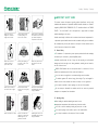
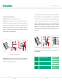
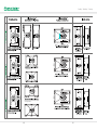
Phono Solar Technology Co., Ltd.
PHONO SOLAR TECHNOLOGY CO., LTD.
Address : No. 1 Xinghuo Rd., Nanjing Hi-tech Zone, Nanjing, China
Tel: +86 25 5863 8000
Fax: +86 25 5863 8009
E-mail: [email protected]
Website: www.phonosolar.com
Photovoltaic Module
Installation Manual (IEC)
Version: EN-IM-IEC-20150115
Copyright © PHONO SOLAR, 2015
CONTENTS
1. IMPORTANT SAFETY GUIDE
2. PRODUCT IDENTIFICATION
3. MECHANICAL INSTALLATION
4. ELECTRICAL INSTALLATION
5. MAINTENANCE
6. DISCLAIMER OF LIABILITY
7. DISPOSAL OF END OF LIFE PRODUCTS
Stability / Reliability / Creativity
1 IMPORTANT SAFETY GUIDE
Module (IEC)
RatedPower
Tolerance
RatedPowerVoltage
Open iC
rcuit
Tolerance
RatedPowerVoltage
RatedPower
National
Power
This manual contains information regarding product identification and the safe
Module (IEC)
RatedPower
Tolerance
RatedPowerVoltage
Open iC
rcuit
Tolerance
RatedPowerVoltage
RatedPower
National
Power
installation and maintenance of photovoltaic modules (hereafter referred to as “module”)
supplied by PHONO SOLAR TECHNOLOGY CO., LTD. (hereafter referred to as “PHONO
SOLAR”).
DO NOT use mirrors or
magnifiers to concentrate
sunlight onto the module.
DO NOT paint the module
or attach anything on to
the back of the module.
DO NOT attempt to disassemble
the modules, and do not remove
any attached nameplates or
components from the module.
The term “module” can be interpreted as a single module or multiple
modules depending on the context.
Installers must already be familiar with the mechanical and electrical requirements for
a photovoltaic system. Installers must also read this manual carefully prior to installation.
We recommend that you keep this manual in a safe place for future reference and in
case of future sale or disposal of the module.
1.1
General Safety
The installation of a photovoltaic system requires specialized skills and knowledge
Module (IEC)
RatedPower
Tolerance
RatedPowerVoltage
Open iC
rcuit
Tolerance
RatedPowerVoltage
RatedPower
National
Power
and must only be carried out by licensed/qualified persons.
DO NOT lift or move the
module by holding the
junction box or cable.
DO NOT place anything on
the module or press on the
module surface.
Toleranc
e
R t dP
DO NOT drop the module or
allow objects to fall on the
module.
Installers should assume all risks of injury and do everything to avoid potential
damages and risks that might occur during installation, including but not limited to,
the risks of electric shock.
PHONO SOLAR modules do not need special cables for connection. All of the
modules have permanent junction boxes, cables and connectors.
Module (IEC)
Rated
t Power
To
Tolerance
RatedPowerVoltage
Open iC
rcuit
Tolerance
RatedPowerVoltage
RatedPower
National
Power
Do not use mirrors or magnifiers to concentrate sunlight onto the modules.
The modules generate DC electrical energy from sunlight. They are designed for
outdoor use and can be mounted onto frames on rooftops or in the ground etc.
Do not paint the module or attach anything on to the back of the module.
DO NOT expose the back of
the module to direct sunlight.
DO NOT install or handle
module in wet or strong windy
conditions.
DO NOT wear metal ornaments
while handling the module or
during the installation.
Do not attempt to disassemble the modules, and do not remove any attached
nameplates or components from the modules.
1.2
Handling safety
When handling the module insulated gloves must be worn.
Inappropriate transportation and installation may break the module.
Do not lift or move the module by holding the junction box or cable.
Do not place anything on the module or press on the module surface.
DO NOT drill holes in the frame.
DO NOT use module near
equipment or in places where
flammable gases may be
generated or collected.
Insulated gloves must be worn
while handling the module and
during the installation.
Do not drop the module or allow objects to fall on the module.
01
Stability / Reliability / Creativity
Do not expose the back of the module to direct sunlight.
Do not wear metal ornaments while handling the module.
The frame of the modules may be grounded according to local, regional and state
safety and electrical standards.
Do not install or handle modules in wet or strong windy conditions.
1.3
Installation safety
Only Balance of System (BOS) components that conform with local, regional
and state safety electricity standards should be used to avoid affecting module
Local, regional and state laws and regulations must be adhered to while installing
a photovoltaic system. For example, any necessary licenses must be obtained prior
performance and/or module damage.
1.4
to the installation commencing. Regulations around vehicles and ships must also be
observed during the installation.
Fire Safety
Consult your local authority for guidelines and requirements for building or
structural fire safety.
Observe all safety rules for the other system components, including the cables,
connectors, charging controllers, inverter and storage battery etc.
Roof constructions and installations may affect the fire safety of a building; an
improper installation may create a hazard in the event of a fire.
Do not place the modules near a location where flammable gases are either
generated or collected.
Use components such as ground fault circuit breakers and fuses as required by the
local authorities.
Insulated gloves must be worn during the installation.
Do not wear metal ornaments during the installation.
Do not use the modules near a location where flammable gases are either generated or
collected.
Do not drill holes in the frame.
The modules have been rated Fire Class C, and are suitable for mounting onto a
Under normal conditions, a module is likely to produce more current and/or
Class A roof.
voltage than reported under Standard Test Conditions (STC). Accordingly, the values
of ISC and VOC marked on the module nameplate should be multiplied by a factor
when determining the component voltage ratings, conductor current ratings, fuse sizes,
and the size of controllers connected to the photovoltaic system. The exact factor
value should be suggested by a licensed/qualified person.
The live connector may cause fire. spark or lethal shocks even when the modules
are not connected.
Electricity can be generated when the modules are exposed to sunlight, even if
they are not connected.
2 PRODUCT IDENTIFICATION
On the back of each module there are 2 labels that provide the following information:
Nameplate: Describes the product type, rated power, rated current, rated voltage, open
circuit voltage, short circuit current, all as measured under STC; weight, dimensions etc.;
the maximum system voltage of 1000V DC.
should not be bigger than the maximum system voltage marked in the
It is dangerous to touch 30V DC or higher, so never open
the electrical connectors or unplug the electrical connectors while the circuit is under
load, and do not touch the live connectors during the installation when the modules
are exposed to sunlight.
Warning: The value of Voc multiplied by the number of modules in series
nameplate.
Barcode: This is used to identify each module. Each module has a unique and traceable
serial number in the form of barcode. The barcode of each PHONO SOLAR module has
15 letter/digits.
Children should be kept away from the photovoltaic system.
Warning: Do not remove the nameplate or barcode. The PHONO SOLAR product
In order to prevent current and voltage generation during installation an opaque
warranty will be void if either the module nameplate or barcode is removed.
board can be used to cover the modules.
Only use licensed/qualified insulated tools.
02
03
Stability / Reliability / Creativity
3 MECHANICAL INSTALLATION
When fixing the modules using the 8 mounting slots, all the hardware (washers,
(Note: All instructions hereafter are for reference only. A licensed/qualified person or
screws and nuts) shall be made of stainless steel;
installer must be responsible for the design, installation, mechanical load calculation
and security of the photovoltaic system.)
structure, PVC washers or neoprene tape shall be interposed between the two metals;
3.1
Select suitable locations for installation
Select a suitable location for installing the modules.
PHONO SOLAR recommends that to achieve the best performance the modules
should face south in northern latitudes and north in southern latitudes. The exact tilt
angle and orientation of mounted modules should be recommended by a licensed/
qualified installer.
The modules should be completely free of shade at all times.
Do not place the modules near a location where flammable gases are either
generated or collected.
Note1: Saline environments can accelerate the processes of electrical insulation losses
and galvanic corrosion, especially when different metals with high electrochemical
potential come into contact each other.
To avoid possible galvanic corrosion between the aluminum frame and the support When grounding the module frames, stainless steel hardware must also be used.
3.2
Select suitable mounting rails
Please observe the safety regulations and installation instructions included with the
mounting rail. If necessary please contact the supplier directly for further information.
The modules must be safely set onto the mounting rail. The whole rail supporting the
photovoltaic system must be strong enough to resist potential mechanical pressures
caused either by wind or snow, in accordance with local, regional and state safety (and
other associated) standards.
Make sure that the mounting rail will not deform or affect the modules when it
expands as a result of thermal expansion.
The mounting rail must be made of durable, anti-corrosive and UV-resistant materials.
In saline environments, Phono Solar PV modules must be installed under the following
conditions:
Modules shall not be installed in locations where they will come into direct contact
with salty water, that is, in offshore (e.g. platforms) and marine (e.g. piers, boats)
applications.
Modules installed in locations where the distance from the sea is less than 500 m shall fulfill the following requirements:
The modules shall be mounted with a minimum tilt angle of 10° in respect to the horizon;
When fixing the modules using the 8 mounting slots, all the hardware (washers,
screws and nuts) shall be made of stainless steel;
To avoid possible galvanic corrosion between the aluminum frame and the support structure, PVC washers or neoprene tape shall be interposed between the two metals;
When grounding the module frames, stainless steel hardware must also be used.
2
Note : In environments where ammonia is present, Phono Solar PV modules must be
installed under the following conditions:
04
05
Stability / Reliability / Creativity
The module clamps should not come into contact with the front glass and must not
3.3
deform the module frame. Avoid any shadowing effects from the module clamps.
Select suitable mounting methods
PHONO SOLAR modules can be mounted using two methods:
The module frame can not be modified under any circumstances. Regardless of the
Screw Fitting: Use corrosion-proof screws in the existing installing holes in the
orientation chosen, at least 4 clamps must be used on each module. For portrait
module frame. Each module has 8 mounting holes for securing the module on the
orientation, 2 clamps should be attached to the long sides of the module and for
mounting rail. The module frame must be attached to a mounting rail using M8
landscape orientation 2 clamps should be attached to the short sides of the module.
corrosion-proof screws together with spring washers and flat washers in symmetrical
Depending on the local wind and snow loads, additional clamps may be required. The
locations on the module. The applied torque should be 8Nm. Please find detailed
applied torque should be about 8Nm. Please find detailed mounting information in the
mounting information in the below illustration:
below illustration:
Module Frame
Clamp
Mounting Rail
Module Frame
M8 Bolt
Module Frame
Mounting Rail
M8 Screw
Module installed using Clamp Fitting method
Mounting Rail
M8 Screw
Split Washer
M8 Nut
Flat Washer
Select the appropriate installation method depending on the load (see below for more
detailed information).
Module installed using Screw Fitting method
Clamp fitting: Using suitable module clamps on the LONG side of the module frame
F Type
1580mm × 808mm × 35mm
DIAMOND Series
to mount the modules is “portrait orientation” mode, while on the SHORT side of the
ONYX Series
module frame is “landscape orientation” mode.
U Type
DIAMOND Series
1640mm × 992mm × 35/40/45mm
ONYX Series
T Type
DIAMOND Series
1956mm x 992mm x 45/50mm
06
ONYX Series
07
Stability / Reliability / Creativity
A
A
(300mm)
A
A
Mounting rails may run perpendicularly or parallel
to the long side frame
B
B
410-490mm
B
B
B
Mounting rails may run perpendicularly or parallel
to the long side frame
08
09
Stability / Reliability / Creativity
3.4
Warning: Do not attempt to drill holes in the module frame or in the glass surface of
4.9
the module. Any such modifications will void the PHONO SOLAR product warranty.
strongly recommends to use anti-PID solar modules in wet regions (i.e. shores,
When installing a module on a pole ensure that the pole and mounting rail can
In order to reduce the risk of potential induced degradation (PID), Phono Solar
wetlands), or to use the system negative grounding where the negative polarity of
withstand anticipated local winds. The pole must be installed on a secure base.
the PV modules array (i.e. negative grounding at the DC bus bar level) is connected
3.5
to the ground. Failure to comply with this recommendation may reduce the module
Ensure that the installation height is such that the lowest modules will not be
covered by accumulated snow or shaded by the surroundings.
3.6
regional and state standards and regulations.
3.7
performance and will invalidate the limited power warranty of the module.
Ensure that there is adequate ventilation under the modules, conforming to local,
A minimum distance of 10cm, between the roof plane and the frame of the
5 MAINTENANCE
In order to ensure optimum module performance, PHONO SOLAR recommends the
module is generally recommended.
following:
3.8
5.1
Observe the linear thermal expansion of the module frames. A minimum distance
of 1cm between two modules is generally recommended.
4 ELECTRICAL INSTALLATION
(Note:
All instructions hereafter are for reference only. A licensed/qualified
person or installer must be responsible for the design, installation, mechanical
load calculation and security of the photovoltaic system.)
4.1
Any hardware used must be compatible with the mounting material to avoid
galvanic corrosion.
4.2
Only use connectors that are designed for photovoltaic systems and that match
If necessary, the glass front of the module can be cleaned with water and a
soft sponge or cloth. A mild, non-abrasive detergent can be used to remove more
stubborn stains.
5.2
Check the electrical and mechanical connections periodically and make sure they
are clean, safe, complete and secure.
5.3
In the event of a problem, consult with a licensed/qualified person.
6 DISCLAIMER OF LIABILITY
Since it is impossible for PHONO SOLAR to control installation, operation, application
and maintenance of the photovoltaic system according to this instruction, PHONO
PHONO SOLAR modules.
SOLAR does not accept responsibility and expressly disclaims liability for any loss,
4.3
damage, or expense arising out of or in any way connected with such installation,
When working with the connectors only use tools as recommended by the
connector manufacturer.
operation, use or maintenance.
4.4
PHONO SOLAR will not take any responsibilities for any possible violation of patent
PHONO SOLAR recommends that the same type of modules are connected
together in order to avoid any system power loss.
4.5
The maximum number of series connected modules depends on system design,
the type of inverter used and environmental conditions.
4.6
Select insulated cables that are able to resist to ultraviolet radiation and
extreme weather conditions.
4.7
The rated voltage of the cable chosen must be appropriate to the overall
rights and third party rights that are related to application of the solar energy system.
No permission of patents is given through implication.
The information of this instruction is from knowledge and experience of PHONO
SOLAR, and so it is reliable. However, the instructions and suggestions of this
instruction do not make an external or internal of guarantee. PHONO SOLAR reserves
the right to revise this instruction, products and all the information about products
without prior notification to customers.
maximum voltage of the system.
4.8
The module frame may be grounded according to local, regional and state
safety and electrical standards. Ensure that a recommended connector or equivalent
7 DISPOSAL OF END OF LIFE PRODUCTS
Phono Solar is a member of PV CYCLE, a European non-profit association managing
is used for the grounding cable. The grounding cable must be properly fastened to
a collection and recycling scheme for end-of-life solar modules throughout Europe.
the module frame.
Please visit the website: http://www.pvcycle.org/ for further information.
10
11
Stability / Reliability / Creativity
Limited Warranty for PV-Modules
(Version EN-W-SM-2015-V1)
Phono Solar Standard PV Modules with the Model Names covered under this warranty are:
PSXXXM-24/F (XXX = 180, 185, 190, 195,200,205,210)
PSXXXM-20/U (XXX = 230,235,240,245,250,255,260,265,270)
PSXXXP-20/U (XXX = 230,235,240,245,250,255,260,265)
PSXXXM-24/T (XXX = 280,290,300,310,320,330)
PSXXXP-24/T (XXX = 280,290,300,310,320,330)
2 Limited Peak Power Warranty - Limited Remedy
Twelve (12) years
If, within a period of Twelve (12) years from the date of delivery by Phono Solar to
the first buyer any Product exhibits a power output less than 90% of the minimum “Peak
Power at STC”1 as specified as of the Phono Solar´s product label, provided that such
loss in power is determined by Phono Solar (at its sole and absolute discretion) to be
due to defects in material or workmanship, Phono Solar will, at its sole option, either
(1)replace such loss in power by either (a) providing additional Product(s) to the Customer to make up for such loss in power or (b) replacing the defective The product (hereinafter the “Product”) in this Warranty means the Standard PV Module(s)
Products(s) at the option of Phono Solar or
manufactured by Phono Solar Technology Co., Ltd. (hereinafter the “Phono Solar”). The
(2)refund the percentage of the cost of the Product(s) (as measured by the then Phono Solar warrants its Product(s) in compliance with the terms and conditions as
prevailing market price for similar Product(s) to the Customer representing the stipulated below.
percentage of the power output less than 90% the minimum “Peak Power at STC”1 as specified as of the Phono Solar’s product label.
The Customer in this Warranty means the individual person or company who purchases
Phono Solar Product.
The remedies set forth in this clause 2 shall be the sole and exclusive remedies
provided under the “Limited Peak Power Warranty”
This “Limited Warranty for PV-Modules“ is valid for all Standard Modules delivered from
Phono Solar since January 1st, 2015
1 Limited Product Warranty –Repair or Replacement
Ten (10) years
Twenty Five (25) years
If, within a period of Twenty Five (25) years from the date of delivery by Phono Solar
to the first buyer any Product exhibits a power output less than 80% of the minimum
“Peak Power at STC”1 as specified as of the Phono Solar´s product label, provided
Phono Solar warrants that the Product including factory-assembled DC connectors and
that such loss in power is determined by Phono Solar (at its sole and absolute
cables, if any, will be free from defects in material and workmanship under normal
discretion) to be due to defects in material or workmanship, Phono Solar will, at its
application, installation, operation, use and service conditions. If Product fails to
sole option, either
conform to this warranty, within a period of ten (10) years from the date of delivery
(1)replace such loss in power by either (a) providing additional Product(s) to the by Phono Solar to its first buyer, Phono Solar will, at its sole discretion, either
Customer to make up for such loss in power or (b) replacing the defective repair the defective Product(s) at no charge; or replace the defective Product(s) or
Products(s) at the option of Phono Solar or
part thereof by a new or remanufactured equivalent at no charge, within the above
(2)refund the percentage of the cost of the Product(s)(as measured by the then specified period. This repair or replacement remedy shall be the sole and exclusive
prevailing market price for similar Product(s) to the Customer representing the remedy provided under the “Limited Product Warranty” and shall not extend beyond
percentage of the power output less than 80% the minimum “Peak Power at STC”1 the ten years period set forth herein.
as specified as of the Phono Solar’s product label.
This “Limited Product Warranty” does not warrant a specific power output, which shall
The remedies set forth in this clause 2 shall be the sole and exclusive remedies
be exclusively covered under clause 2 hereinafter (“Limited Peak Power Warranty”).
provided under the “Limited Peak Power Warranty”
12
13
Stability / Reliability / Creativity
3 Exclusions and Limitations
4 Limitation of Warranty Scope
(1)In any event, all warranty claims must be received within the applicable warranty These warranties as set forth herein are expressly in lieu of and exclude all other
warranties of any kind whatsoever, whether express or implied, including but not
period for this warranty to be effective.
(2)The “Limited Product Warranties” and the ”Limited Peak Power Warranties” do not apply to any Product(s) which have been subjected to:
limited to warranties of merchantability, of fitness for particular purpose, use, or
application, of non-infringement and all other obligations or liabilities on the part of
Misuse, abuse, neglect or accident;
Phono Solar, unless such other obligations or liabilities are expressly agreed to in
Alteration, improper installation or application;
writing signed and approved by Phono Solar to the broadest extent permitted by law.
Non-observance of Phono Solar’s installation manual;
Impairments caused by external effects, such as e.g., dirt stains, smoke, damages Phono Solar shall have no responsibility or liability whatsoever for damage or injury to
caused by salt, by chemicals not explicitly authorized for use, e.g. for cleaning. persons or property, or for other loss or injury resulting from any cause whatsoever
Repair or modifications by someone other than an approved service technician of arising out of or related to the Product(s), including, without limitation, any defects in
Phono Solar;
the Product(s), or from use or installation. Under no circumstances shall Phono Solar
Power failure surges, lightning, flood, fire, accidental breakage or other events out of Phono Solar’ s control;
Caused by external events including but not limited to defective equipment parts, appliances, system components like, connecting cables, invertors, or the like, be liable for any special punitive, incidental, or consequential damages, howsoever
caused, including but not limited to loss of use, loss of profits, loss of production, or
loss of revenues, arising, directly or indirectly from the sale or use of any Product(s),
which have been coupled with the Module by anyone other than Seller, or caused whether such claim is based on warranty, contract, negligence, strict liability or
by defective system design, configuration, or installation planning;
otherwise, Phono Solar´ s aggregate liability, if any, in damages or otherwise, shall not
Removal of Modules and reinstallation at a new site;
exceed the invoice value as paid by the Customer, for the single unit of Product(s)
Installation on mobile platforms or in a marine environment; direct contact with involved. The rights and limitations herein shall leave unaffected any legal rights
corrosive agents or salt water; pest damage; or malfunctioning system components;
Alteration, removal or obliteration of the original Module label;
Other events that are reasonably beyond the control of Phono Solar.
(3)Both the “Limited Product Warranties” and “Limited Peak Power Warranties” do not cover any costs associated with installation, removal or re-installation of the PV-modules and (except as explicitly set forth in the final paragraph of Section 5) customs clearance or any other costs for return of the Product(s); .
(4)Both the “Limited Product Warranties” and “Limited Peak Power Warranties” do not cover cosmetic blemishes associated with installation, or the normal wear and tear of Phono Solar Modules.
existing under mandatory applicable laws.
5 Obtaining Warranty Performance
If the Customer has a justified claim covered by this “Limited Warranties for PV
Modules”, an immediate notification directly to Phono Solar shall be filed by mailing
a registered letter in writing to the address of Phono Solar listed hereunder, or
by, sending an email letter to the email account of Phono Solar Service Center
listed hereunder as soon as becoming aware of the circumstances which constitute
a warranty case. Together with the notification, the Customer should enclose the
following information:
The necessary contact information of the Customer, including its name, address,
telephone, email, etc.,
The corresponding serial number of the Product(s)
The date on which the Product(s) have been delivered and installed
14
15
Stability / Reliability / Creativity
The pictures of the defective Module which show the defect and/or the pictures
which show the shadowing situation at the installation location
The timely receipt of the notification by Phono Solar shall be decisive.
The return of any PV-modules will not be accepted unless prior written authorization
for the return and evaluation of the claimed defect has been given by Phono
Solar. To the extent necessary for processing the return request Phono Solar or its
authorized person shall be given commercially reasonable access to the Product(s) for
inspection and analysis of the claimed defect. In connection with both the “Limited
Product Warranties” and “Limited Peak Power Warranties”, Phono Solar shall reimburse
become the property of Phono Solar made for their disposal. Phono Solar has the
right to deliver another type (different in size, color, shape and/or power) in case
Phono Solar discontinued producing the replaced Product(s) at the time of the claim.
9 Warranty Transfer
This warranty is transferable from the original Customer to any assignee and remains
in effect for the time period remaining under the limited warranties, provided the
Product remains installed in its original location at the warranty registration.
Customer for reasonable, customary and documented transportation charges by
10 Force Majeure
sea freight for both the return of the Product(s) and reshipment of any repaired or
Phono Solar shall not be responsible or liable in any way to the customer or any
replaced Product(s), only if this cost is authorized by Phono Solar customer service
third-party arising from any non-performance or delay in performance of any terms
department.
and conditions of sale, including this "Limited Warranty for PV-Modules ", due to acts
God, war, riots, strikes, warlike conditions, plague or other epidemics, fire, flood, or
6 Severability
any other similar cause or circumstance beyond the reasonable control of such Phono
If a part, provision or clause of this “Limited Warranty for PV-Modules”, or
the application thereof to any person or circumstance, is held invalid, void or
unenforceable, such holding shall not affect and shall leave all other parts, provisions,
clauses or applications of this “Limited Warranty for PV-Modules”, and to this extent
such other parts, provisions, clauses or applications of this “Limited Warranty for PVModules” shall be treated as severable.
Solar. In such cases, performance by Phono Solar of this Limited Warranty shall be
suspended without liability for the period of delay reasonably attributable to such
causes.
1 “Peak Power at STC” is the power in Watt peak that a PV- Module generates in its
Maximum Power Point.
“STC” are as follows:
7 Disputes
Light spectrum of AM 1.5, (b) an irradiation of 1000 W per m2 and (c) a cell
In case of any discrepancy in a warranty-claim, a first-class international test-institute
such as Fraunhofer ISE in Freiburg/ Germany, TÜV Rheinland in Cologne/ Germany
temperature of 25 degree centigrade at right angle irradiation.
The measurements are carried out in accordance with IEC 61215 as tested at the
or ASU Arizona State University shall be involved to judge the claim finally. All fees
connectors or junction box terminals – as applicable – per calibration and testing
and expenses shall be born by the losing party, unless otherwise awarded. The final
standards of Phono Solar valid at the date of manufacture of the PV-modules. The
explanation right shall be borne by Phono Solar.
power output shall be measured by a laboratory approved by Phono Solar.
8 Various
The repair or replacement of the Product(s) or the supply of additional Product(s),
does not cause the beginning of new warranty terms, nor shall the original terms of
this “Limited Warranty for PV-Modules” be extended. Any replaced Product(s) shall
16
17
NOTES: