1
LS Series Cooling Towers
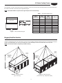
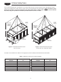
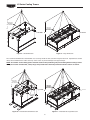
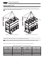
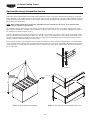
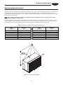
See Table 3 for the minimum “H” dimensions for rigging the fill section for both standard and extended lifts.
Table 3 – Minimum “H” Dimension for Fill Section Rigging
Unit
Footprint
Minimum
“H”
4' x 6'
4' x 9'
4' x 12'
4' x 18'
5' x 12'
5' x 18'
8P' x 12'
8P' x 18'
8P' x 24'
8P' x 36'
10' x 12'
10' x 18'
10' x 24'
10' x 36'
8'
10'
15'
19'
15'
19'
15'
19'
15'
19'
15'
19'
15'
19'
Assembly of the Fill Section to the Pan-Fan Section
Before assembling the fill section to the pan/fan section,
remove any loose parts shipped in the pan. On small
centrifugal fan units, the fan motor guard is normally shipped in
the basin to avoid damage. It should be attached to the unit
with the self-tapping screws provided. On double fan sided
centrifugal units, the fan motor guards are shipped in a
separate crate with the motors, see the “Motor Installation”
section in this bulletin.
UPPER
UPPE
R SE
SECTION
CTION
ION
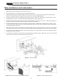
Wipe the flanges on the bottom of the fill section. Check to see
that the water distribution connection on the fill section is in the
correct position relative to the pan-fan section (see certified
print). Confirm that sealer tape has been applied to the top of
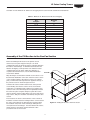
the pan-fan section as shown in Figures 6 and 7.
ATTACH USING
G
3/8Ø H
ARD
DWAR
WA
W
ARE
AR
HARDWARE
DRIFT
DR
IFT PINS
PINS
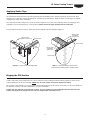
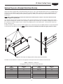
Lower the fill section to within several inches of the pan-fan
section making sure the two sections do not touch and the
sealer tape is not disturbed. Place drift pins (see Figure 12) in
at least 3 of the corner mounting holes and gradually lower the
fill section into place using the drift pins to guide the section
down accurately onto the mating flange. On 18 foot and 24 foot
long sections, drift pins should be used midway along the sides
as well.
Place fasteners in all four corner bolt holes. Then continue to
install the rest of the fasteners working from the corners toward
the center, using drift pins to align the holes. A fastener must
be installed in every hole on the side flanges although none
are required on the end flanges. For units with two fill sections,
mount the first as described, and then follow the same
procedure for the second section.
Figure 12 – Mating Fill Section to Pan-Fan Section
M
7