1
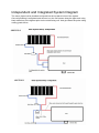
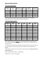
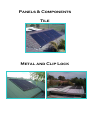
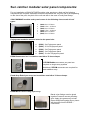
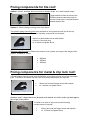
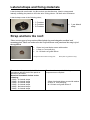
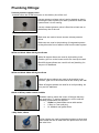
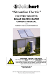
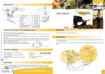
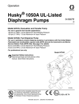
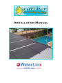
Installation Manual Independent and Integrated System Diagram The return pipe must be plumbed and glued into the top barrel union of the system. Once all plumbing is completed and secured, run the roof sensor along the pipe work using black cable ties to the highest point on the north facing roof. And glue down the probe using roofing grade silicon. SKETCH B SKETCH C Installation Overview: The Sun Command solar panels you have chosen for the purpose of heating your swimming pool will give you many years of enjoyment. The following information is a basic outline for installing a Sun Command Solar Pool Heating system. This will guide you through the installation of your system however it is strongly recommended that a tradesman or handyman with practical knowledge of building and basic pool filtration carry out the installation. He /She must be competent working with heights and should have a full under-standing of safety regulations and requirements. Tools Required These tools may be required during installation: Hacksaw Corking gun (for Silicon glue) Cordless Drill Hammer Drill Hammer Drill bit 5, 6.5 or 7mm (Masonry) 5/16 Hex head bit Ladder Tape Measure Marking Pen/ Pencil Safety glasses Wire Cutters for cutting cable ties Scissors Gloves ADDITIONAL EQUIPMENT: Additional equipment necessary to complete installation: 1 x Tube of roofing grade silicon 25 - 50 x green 6.5mm or blue 7mm wall plugs 25 - 50 x 50mm Hex head roofing screws with washers 5mm Nylon knock ins Black Cable ties White Cable ties Panel Information: Table 1 Panel Dimensions: PANEL TYPE LENGTH (mm) WIDTH OF HEADER (mm) AREA (m2) WEIGHT EMPTY (kg) WEIGHT FULL (kg) 2080 2040 1350 2.50 6.5 15.5 2580 2540 1350 3.13 8.0 19.25 3080 3040 1350 3.75 9.5 23.0 4080 4040 1350 5.00 12.5 30.5 5080 5040 1350 6.25 15.5 38.5 NOTE: The dimensions given above are actual panel sizes. When installing, additional space must be allowed for pipe work connections Table 2 Panel Requirements: POOL SIZE (m2) 2080: QTY 2580: QTY 3080: QTY 4080: QTY 5080: QTY 12 3 2 2 1 1 16 4 3 3 2 2 20 5 4 3 2 2 24 6 5 4 3 2 28 7 5 5 3 3 32 8 6 5 4 3 36 9 7 6 4 3 40 10 8 6 5 4 44 11 8 7 5 4 48 12 9 8 6 5 52 12 10 8 6 5 Panel quantities above are average to give an 8 degrees Celsius temperature rise above ambient temperature, assuming the use of a pool cover in cooler periods and during the night. For pool sizes other than those indicated, select a panel area to pool surface area of 60 to 70% based on a North facing roof with no shade and a average pitch of 23 degrees. West facing roofs require 70 to 80 % panel to pool surface area. Never fix panels on south facing roof. 80m2 pool area would require 13 x 3080 panels. (80m2 x 60% - 3.75m2 = 12.8 panels). Panels & Components Tile Metal and Clip Lock Sun catcher modular solar panel components: For any installation of SUN CATCHER modular solar panels on a tiled roof the following components are required: Quantities of these components will vary from job to job depending on the size of the pool, the pitch of the roof and also in the case of multi panel arrays. SUN COMMAND modular solar panels come in the following sizes to suit all roof types: (2080) 2m x 1250mm (2580) 2.5m x 1250mm (3080) 3m x 1250mm (3580) 3.5m x 1250mm (4080) 4m x 1250mm (5080) 5m x 1250mm Polystyrene Insulation material suited to the panel size: (2580) - 2m Polystyrene panel (3080) - 2.5m Polystyrene panel (3580) - 3m Polystyrene panel (4080) - 3m Polystyrene panel (5080) - 2 x 2m Polystyrene panel EPDM Connectors inc 2 x stainless steel 40 to 70 hose clamps. 2 EPDM Rubber connectors per panel are required on single array systems Additional 2 EPDM connectors are required for each addition array. Panel Stop Ends 2 per array. Inc Ix stainless steel 40 to 70 hose clamps. EPDM Barrel Union Fitting 2 per array. Barrel union fittings must be glued together Pressure cement plumbing glue. Apply glue generously to both pieces and push together d grey insert will then slide into the EDPM - Connectors. Fixing components for tile roof: Option I: Small L brackets with round /role for header straps. inc I meter header straps These should be fitted on each of the EPDM connectors and stop ends on the top header pipe. If required bottom header pipe as well. Option 2: Plastic sliding mounting pads 2 per panel. Two plastic sliding mounting pads must be fitted on every panel at each end of the top header pipe. To fasten to a tile roof to following components are required: - 50mm hex head timber screw with washer - 6.5mm or 7mm wall plug - N- 10 black roof grade silicon Stainless steel S hooks are fitted at the bottom of the system and support the weight of the panels. available in 3 sizes 200mm 350mm 450mm Fixing components for metal & clip lock roof: 2 Plastic sliding mounting pads must be fitted on every panel at each end of the top header pipe. To fasten to a metal or clip lock roof to following components are required: 50mm hex head self tapper screw with washer N– 10 black roof grade silicon Stainless steel U shaped hooks are fastened to the bottom screw line of the roof and support the weight of the panels. To fasten to a metal or clip lock roof the following components are required: 50mm hex head self tapper screw with washer N– 10 black roof grade silicon Lateral straps and fixing materials Lateral strap with cam buckle. Inc I0 cm short cam buckle strap. Used to strap panels laterally, enabling the panels to lift in the wind. Giving them a 140 km/h wind resistance. Lateral straps come in the following sizes; 1.5 meters 4.5 meters 8.5 meters 1 per lateral strap Strap anchors tile roof: There are two types of strap anchors Black plastic lug and triangular anodised steel mounting plate. These are anchored to the roof in between each panel and the strap is feed through them. 50mm hex head timber screw with washer 6.5mm or 7mm wall plug N– 10 black roof grade silicon Triangular anodised steel mounting plate The number of straps required will be in accordance with the size of the panel on which they are fitted. Waterlinx Australasia insists on the following: - (2080) - 2x Lateral straps - (2580) - 2x Lateral straps - (3080) - 2x Lateral straps - (3580) - 3x Lateral straps - (4080) - 3x Lateral straps - (5080) - 3x Lateral straps Black plastic lug (sewed to strap) To anchor the straps the following components are required: - 50mm hex head timber screw with washer - 6.5mrn or 7mm wall plug - N- 10 black roof grade silicon 7 Plumbing fittings: Vacuum pressure release valve. Installed before the EPDM connector on the delivery line of the roof. Vacuum pressure release valve is spring loaded on aids in bleeding the solar system upon start up and then drains the system when it is not running. Vacuum release pressure valve is fitted into a black tee on the delivery line of the roof While and Black 40mm tees. Black tees are used to house vacuum release pressure valves. White tees are used in the plumbing of integrated systems as they direct the flow of water to and from the solar system. White and black 40mm 90 degree elbows White 90 degree elbows are used in all plumbing in the filtration, pipe run to the house and for the rises up the wall. Black 90 degree elbows are used for all roof plumbing. As they are UV stabilised. White and black 40mm 45 degree elbow White 45 degree elbows are used in all plumbing in the filtration, pipe run to the house and for the rises up the wall. Black 45 degree elbows are used for all roof plumbing. As they are UV stabilised. Black or White powder coated saddles Saddles made to match the colour of the pipe that they are supporting. To anchor saddles to a roof or wall the following components are required 50mm hex head timber screw with washer 6.5mm or 7mm wall plug N- 10 black roof grade silicon 3 Way Valve, 40mm. 3 Way Valves are used in integrated systems to direct and also isolate the flow of water from the pools return line into the solar lines. 2 Way Valve, 40 mm 2 Way Valves are used to isolate the flow of water. Must install on discharge line from solar Pump. Spring check Valve, 40 mm Spring Check Valves must be installed in front of the solar pump and aid in keeping the pump primed. Pressure cement, clear Pressure Cement is used in all plumbing, and must be applied generously to both the internals of the fining and the externals of the pipe of which you are gluing it in to. Dontek V2-Delux Solar Controller. (used in integrated System) Dontek V2-Delux solar controller automatically regulates the water temperature using two thermostats. The first of which is the pool probe and is drilled into the suction line of the pump and sealed using a rubber grommet. The second is a roof probe that must be run onto the highest point of the north facing roof by cable tying it to the pipe work. Dontek V7 Solar Controller (used in independent system) Linx series pumps. Available in sizes: Linx 950 Linx 1100 Linx 1500 Linx 2100 Installation process Metal and clip lock roof: The steps to installing sun command solar panels on a metal or clip lock roof are as follows: Measure or estimate the most suitable spot on the north or North West facing roof of the house to install the system. On the bottom screw line of the roof, in the centre of where the first panel will go, unscrew one of the roof screws and position a stainless steel U hook over the screw hole and screw in again. For clip lock roofs a string line is recommended to line up screw line. Repeat this every 1250 mm in accordance to the number of panels in the system. Slide the panels into the U hooks and line them up flush with one another. Slide in polystyrene insulated sheets underneath each of the panels. This can be done at the top or the sides of each panel. The next step is to join the panels together using EPDM connectors Inc 2x stainless steel 40 to 70 hose clamps. Firmly push the EPDM connector as far as the ridged internals will allow on to the header pipe, slide two stainless steel panel clamps over the EPDM connector ensuring that both screw threads are facing the same way. Push the header pipe of the adjacent panel into the EPDM connector. Repeat until array of panels are joined top and bottom. Allow an entry point for cold water at the bottom of the array of panels and an exit point of hot water at the opposite end at the top of the array. Install EDPM connectors at these points, including two stainless steel panel clamps per connector. At the opposite ends of the array install stop ends including stainless steel panel clamps, one per stop end. Barrel unions must be fitted in the entry and exit points of the panel array. To do so, firstly glue the grey barrel union into the white 50mm to 40mm adapter, ensuring the recessed end is on the outside. Ensure an abundant amount of glue is applied to both the outer surface of the grey adapter and also the inner surface of the white adapter before firmly pushing the grey barrel union into white 50mm-40mm adapter. Connect the grey barrel union recessed end of the glued components to the EPDM connector, ensuring the grey adapter is pushed in firmly and the stainless steel clamp is positioned to tighten into the recess. Tighten stainless steel hose clamps using a power drill with a 7mm hex head drill bit. Perform the above process on both the entry and exist points of the array. Black 40mm pipe is then glued into the white 40-50mm adapter and plumbed and secured using black saddles from the entry and exit of the panel array to the edge of the roof, nearest to your filter& pump area. Use the white 40mm (90deg) elbows, over the gutter and plumb white 40mm high pressure pipe to both inlet and outlet points to the filter area. Using Plastic sliding mounting pads 2 per panel. Slide plastic mounting pad to the right to unlock it, place two of each on the raised section of the tile, under each panel Close as possible the EPDM connectors leaving a minimum of 25mm between pad and panel header for expansion. Mark with a texter the two drill points in each pad, remove pad and drill through tile with a power drill using a 7mm masonry drill bit. Hammer 7mm blue wall plugs into each hole. Silicon around each drill hole and on the bottom of the pad, place pad into set place. Screw to the roof using 50mm hex head self tapping or timber screw with rubber washer. You will need an 8mm text screw drill bit for this. Slide top of pad on to the left locking it in place. Lateral Straps: Lateral straps are required on all Sun Catcher panels, the number of straps required will vary depending on the size of the panel for example: 2m panels require one strap 2.5m and 3m panels require two straps 4m and 5m panels require three straps. Using a texta and a tape measure mark an anchor point before, in-between, and after the array of panels. Drill into set markings using a power drill and a 7mm masonry drill bit. Hammer 7mm blue plugs into each drill hole. Silicon generously around each hole, to prevent any water leaks at a later date. At the beginning of the array screw off the lateral strap using 50mm hex head self tapping or timber screw with washer. Repeat in between each of the panels using either Black plastic lugs or Triangular anodised steel mounting plate. At the end of your row of anchor point’s screw in stainless steel 25mm ratchet strap, pull strap through ratchet and tighten as much as possible. Cut off excess strap and tidy up using cable ties to make system as neat as possible. Installation process Tile roof: The steps to installing sun command solar panels on a tile roof are as follows: Measure the most suitable spot on the north or North West facing roof of the house to install the system, allowing a minimum of one tile at the top of each panel for fastening purposes. At the bottom of the roof, in the centre of where the first panel will go, lift a tile slightly and slide in a stainless steel S hook. Making sure that the S hook is positioned over the back of the tile and around the batten on which the tile is sitting on. Repeat this every 1250 mm in accordance to the number of panels in the system. Slide the panels into the S hooks and line them up flush with one another. Slide in polystyrene insulated sheets underneath each of the panels. This can be done at the top or the sides of each panel. The next step is to join the panels together using EPDM connectors Inc 2x stainless steel 40 to 70 hose clamps. Firmly push the EPDM connector as far as the ridged internals will allow on to the header pipe, slide two stainless steel panel clamps over the EPDM connector ensuring that both screw threads are facing the same way. Push the header pipe of the adjacent panel into the EPDM connector. Repeat until array of panels are joined top and bottom. Allow an entry point for cold water at the bottom of the array of panels and an exit point of hot water at the opposite end at the top of the array. Install EDPM connectors at these points, including two stainless steel panel clamps per connector. At the opposite ends of the array install stop ends including stainless steel panel clamps, one per stop end. Barrel unions must be fitted in the entry and exit points of the panel array. To do so, firstly glue the grey barrel union into the white 50mm to 40mm adapter, ensuring the recessed end is on the outside. Ensure an abundant amount of glue is applied to both the outer surface of the grey adapter and also the inner surface of the white adapter before firmly pushing the grey barrel union into white 50mm-40mm adapter. Connect the grey barrel union recessed end of the glued components to the EPDM connector, ensuring the grey adapter is pushed in firmly and the stainless steel clamp is positioned to tighten into the recess. Tighten stainless steel hose clamps using a power drill with a 7mm hex head drill bit. Perform the above process on both the entry and exist points of the array. Black 40mm pipe is then glued into the white 40-50mm adapter and plumbed and secured using black saddles from the entry and exit of the panel array to the edge of the roof, nearest to your filter& pump area. Use the white 40mm (90deg) elbows, over the gutter and plumb white 40mm high pressure pipe to both inlet and outlet points to the filter area. * Refer to the panel configuration in (Sketch A) to ensure that the panels are installed correctly. Using Plastic sliding mounting pads 2 per panel. Slide plastic mounting pad to the right to unlock it, place two of each on the raised section of the tile, under each panel Close as possible the EPDM connectors leaving a minimum of 25mm between pad and panel header for expansion. Mark with a texter the two drill points in each pad, remove pad and drill through tile with a power drill using a 7mm masonry drill bit. Hammer 7mm blue wall plugs into each hole. Silicon around each drill hole and on the bottom of the pad, place pad into set place. Screw to the roof using 50mm hex head self tapping or timber screw with rubber washer. You will need an 8mm text screw drill bit for this. Slide top of pad on to the left locking it in place. Lateral Straps: Lateral straps are required on all Sun Catcher panels, the number of straps required will vary depending on the size of the panel for example: 2m panels require one strap 2.5m and 3m panels require two straps 4m and 5m panels require three straps. Using a texter and a tape measure mark an anchor point before, in-between, and after the array of panels. Drill into set markings using a power drill and a 7mm masonry drill bit. Hammer 7mm blue plugs into each drill hole. Silicon generously around each hole, to prevent any water leaks at a later date. At the beginning of the array screw off the lateral strap using 50mm hex head self tapping or timber screw with washer. Repeat in between each of the panels using either Black plastic lugs or Triangular anodised steel mounting plate. At the end of your row of anchor point’s screw in stainless steel 25mm ratchet strap, pull strap through ratchet and tighten as much as possible. Cut off excess strap and tidy up using cable ties to make system as neat as possible. PLUMBING: There are two types of solar systems Independent systems where the pool builder has run a suction line from the pool to the filtration, one line from the plant room (filter) to wall of your home, and one which feeds directly back into your pool and will become the return line( solar from roof) this will be hot water. The other will be the discharge line (solar to roof), this will be cold water. The other type is an integrated system or (boosted) system there are no provisions provided for this sys-tem and you will have to do that yourself by cutting into the pools return line. INDEPENDENT SYSTEMS: Identify which pipe is which this can be achieved by blowing down the pipes and watching where they bubble up in the pool. Label pipes. (Refer to Sketch B) Next step is installing a suitable size pump for the system according to the distance between the filtration and the home and the height of the lift to the roof. To do this firstly screw on the barrel unions provided with the pump, these are 50mm fittings. If working with 40mm pipe glue in 50mm to 40mm reducing bush provided. Plumb front union of pump into suction line installing a spring check valve in between the two points, glue should be generously applied to both the pipe and the fitting in all plumbing. The top outlet of the pump will become your discharge line and needs to have a two way valve fitted in the line. In case pump has to be taken out at a later date water can be shut off. Plumb into discharge line provided by builder which will run to the wall of the residence. Next step is plumbing up your rises, the two pipes that run up the wall of the house. Measure the distance between the pipes provided and the eve of the house. Cut white pipes to size and plumb them using 90 degree angles as required to follow the contours of the wall, eve and gutter of the house. Bringing the pipe work out up and over the guttering. These pipes will need to be secured using white 40mm saddles. If mounting on masonry use 5mm nylon knock in anchor plug. For this you will need a 5mm masonry drill bit a power drill and a hammer. It is also a good idea to run the wire for the roof sensor through the saddles at this stage as it makes it quiet difficult after the rises have been secured. Cable tie the wire to the pipe, hiding it from view as much as possible. Once the rises are plumbed over the gutter the pipe colour must change to black as it is UV rated. All plumbing on roof should follow pitch of the roof to achieve the correct angles needed 90 and 45 degree angles must be used, the amount will depend on the pitch of the roof and the angle of which the pipes need to run to meet the system. All pipe work must be secured to industry standards, using 40mm saddles every 1.5 meters. Locate your delivery pipe and glue on a black tee, in the top of this tee glue in a vacuum break valve, which will bleed the air out of the system whilst it is running, and once system is shut off will aid in the draining of the system as well. Plumb and glue the delivery line from the unused opening of the tee into the bottom barrel union of solar system. The return pipe must be plumbed and glued into the top barrel union of the system. Once all plumbing is completed and secured, run the roof sensor along the pipe work using black cable ties to the highest point on the north facing roof. And glue down the probe using roofing grade silicon. INTEGRATED SYSTEMS: Integrated system or (boosted) systems do not have provisions provided for solar heating. These systems are usually on older model pools. Integrated systems must be plumbed into the return line of the pool to achieve the same results as an independent system. The plumbing is installed as follows: (Refer to sketch C) Firstly you will need to locate the return line from the filter to the pool. On the top of the filter you will see a multi port valve, which will have three ports coming from it two on one side and a single port on the other, the single port will have a sight glass this is the waste line. On the right hand side of the multi port, one line will come out of the auxiliary pump and into the filter. this is discharge to the filter (dirty water). The third line through the process of elimination is the return line to the pool; this line should have either a salt water chlorinator, chlorine feeder or nature 2 on it. Once you have established the return line, you must plumb (in order) a spring check valve, with the arrow facing away from the filter and two three way valves pointing down towards the ground. This all needs to be done before the salt water chlorinator. The first three way valve in the line will become your suction line, and will need to be plumbed into the front barrel union of your pump. Bring the plumbing out of the top of the pump and exit out of or away from the plant room (filtration area), using white 90 and 45 degree angles. This is your discharge line. The second three way valve will become the return line, this line will need to be plumbed to the ground and then exit the plant room (filtration area). Both discharge and return lines will need to be run to the wall of the residence, by any means necessary, be it trenching concrete cutting or saddling the pipes to the fence. Next step is plumbing up your rises, the two pipes that run up the wall of the house. Measure the distance between the pipes provided and the eve of the house. Cut set white pipes to size and plumb them using 90 degree angles as required to follow the contours of the wall, eve and gutter of the house. Bringing the pipe work out up and over the guttering. These pipes will need to be secured using white 40mm Saddles. If mounting on masonry use 5mm nylon knock in anchor plug. For this you will need a 5mm masonry drill bit a power drill and a hammer. It is also a good idea to run the wire for the roof sensor through the saddles at this stage as it makes it quiet difficult after the rises have been secured. Cable tie the wire to the pipe, hiding it from view as much as possible. Once the rises are plumbed over the gutter the pipe colour must change to black as it is UV rated All plumbing on roof should follow pitch of the roof to achieve the correct angles needed 90 and 45 degree angles must be used, the amount will depend on the pitch of the roof and the angle of which the pipes need to run to meet the system. All pipe work must be secured to industry standards, using 40mm saddles every 1.5 meters. Locate your delivery pipe and glue on a black tee, in the top of this tee glue in a vacuum break valve, which will bleed the air out of the system whilst it is running, and once system is shut off will aid in the draining of the system as well. Plumb and glue the delivery line from the unused opening of the tee into the bottom barrel union of solar system. The return pipe must be plumbed and glued into the top barrel. Once all plumbing is completed and secured, run the roof sensor along the pipe work using black cable ties to the highest point on the north facing roof. And glue down the probe using roofing grade silicon. PRESSURE TESTING: Integrated: Now that all pipe work, connections, valves and solar panels have been installed, the pool water circulation should be restarted. NOTE: check that the filter multi-port valve is placed into the filter position and all two and three way valves are set to an open position prior to re - connecting or switching on the pool pump. When the water is re - circulating, firstly leave to solar pump turned off i.e. Bypassing the solar panels until good circulation is achieved. When water is circulating efficiently, the solar pump can be turned on/ plugged in, to allow water to flow through the solar panels. At first it will be noted that any air trapped inside the panels will be pushed out into the pool followed by a flow of warm water. Eventually, all air trapped in the panels will be expelled into the pool and a continuous flow of water will then be directed through the solar system. Recheck for any leaks especially at all new connections made into the pipe work system, and also all connections made both on the panels and all plumbing on the roof. Independent: First step is to prime the solar pump this can be achieved by un screwing the lid of the lint pot and either using a bucket of water or a hose fill the pump until it almost over flows. Screw the lid back on hand tight, making sure all of the barrel unions of the pump are hand tightened, and that any two way valves are set to an open position. Turn on/ Plug in pump. When water is circulating efficiently at first it will be noted that any air trapped inside the panels will be pushed out into the pool followed by a flow of warm water. Eventually, all air trapped in the panels will be expelled into the pool and a continuous flow of water will then be directed through the solar system. Recheck for any leaks especially at all new connections made into the pipe work system, and also all connections made both on the panels and all plumbing on the roof. CONGRSATULATIONS: Your solar system is now installed and working.