1
SKOPE PEGASUS
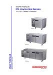
PG100/250/400HFr-2
Horizontal Freezer - REMOTE
PG100HFr-2
MAN6790O Rev. 2.0 Sept. 2008 edition
User Manual
PG250HFr-2
PG400HFr-2
SKOPE PEGUSUS Horizontal Freezer - Remote
PG100/250/400HFr-2
User Manual
MAN6790O
Rev. 2.0 Sept. 2008 edition.
Copyright © 2007 SKOPE Industries Limited.
All rights reserved.
SKOPE Industries Limited reserve the right to alter specifications without notice.
is a registered trade mark of SKOPE Industries Limited.
TRADE MARK INFRINGEMENT
The SKOPE trade mark on this product is infringed if the owner, for the time being,
does any of the following:
• Applies the trade mark to the product after their state, condition, get-up or
packaging has been altered in any manner
•
Alters, removes (including part removal) or obliterates (including part
obliteration) the trade mark on the product
•
Applies any other trade mark to the product
•
Adds to the product any written material that is likely to damage the reputation
of the trade mark
Notice of the above contractual obligations passes to:
• Successors or assigns of the buyer
•
i
Future owners of the product
SKOPE Pegasus Horizontal Freezer - Remote
USER MANUAL
TABLE OF CONTENTS
INSTALLATION
Safety Information. . . . . . . . . . . . . . . . . . . . . . . . . . . . . . . . . . . . . . 4
Fitting Adjustable Legs . . . . . . . . . . . . . . . . . . . . . . . . . . . . . . . . . . 5
Positioning the Cabinet. . . . . . . . . . . . . . . . . . . . . . . . . . . . . . . . . . 6
Shelving . . . . . . . . . . . . . . . . . . . . . . . . . . . . . . . . . . . . . . . . . . . . . 8
Refrigeration System Installation . . . . . . . . . . . . . . . . . . . . . . . . . . 9
ELECTRONIC CONTROLLER
Controller Display . . . . . . . . . . . . . . . . . . . . . . . . . . . . . . . . . . . . . 12
Controller Overview . . . . . . . . . . . . . . . . . . . . . . . . . . . . . . . . . . . 13
Temperature Setpoint . . . . . . . . . . . . . . . . . . . . . . . . . . . . . . . . . . 13
Controller Alarms . . . . . . . . . . . . . . . . . . . . . . . . . . . . . . . . . . . . . 14
MAINTENANCE
Lighting . . . . . . . . . . . . . . . . . . . . . . . . . . . . . . . . . . . . . . . . . . . . . 16
Cleaning . . . . . . . . . . . . . . . . . . . . . . . . . . . . . . . . . . . . . . . . . . . . 17
Cabinet Wiring Diagram . . . . . . . . . . . . . . . . . . . . . . . . . . . . . . . . 18
Refrigeration Unit Wiring Diagram . . . . . . . . . . . . . . . . . . . . . . . . 22
Servicing . . . . . . . . . . . . . . . . . . . . . . . . . . . . . . . . . . . . . . . . . . . . 24
Troubleshooting . . . . . . . . . . . . . . . . . . . . . . . . . . . . . . . . . . . . . . 24
HACCP . . . . . . . . . . . . . . . . . . . . . . . . . . . . . . . . . . . . . . . . . . . . . 24
Contact Addresses . . . . . . . . . . . . . . . . . . . . . . . . . . . . . . . . . . . . 25
Warranty . . . . . . . . . . . . . . . . . . . . . . . . . . . . . . . . . . . . . . . . . . . . 25
SKOPE Pegasus Horizontal Freezer - Remote
TABLE OF CONTENTS
ii
INSTALLATION
Safety Information
When using any electrical appliance, safety precautions should always be
observed. Read these instructions carefully and retain for future reference.
•
When used by, or near, young children or infirm persons, close supervision is
necessary. Young children should be supervised to ensure that they do not
play with the appliance.
•
Do NOT use this appliance for other than its intended use.
•
Do NOT cover the grilles or block the entry or exhaust of airflow by placing
objects up against the refrigeration unit.
•
Do NOT probe any opening.
•
Only use this appliance with voltage specified on the rating label.
•
Ensure adequate ventilation of the SKOPE refrigeration unit.
•
Be careful not to touch moving parts and hot surfaces.
•
Regulations require that all electrical work be carried out by authorised
persons. For your own safety, and that of others, ensure this is done.
•
If the supply cord becomes damaged, it must be replaced by a SKOPE
authorised service agent, or similarly qualified person, in order to avoid a
hazard.
•
This chiller is not designed to be stable in motion. Exercise caution when
moving or transporting this chiller.
Caution:
Disconnect the cabinet from the mains power supply before attempting any
cleaning or maintenance.
4
SKOPE Pegasus Horizontal Freezer - Remote
INSTALLATION - Safety Information
Fitting Adjustable Legs
Packed inside the cabinet is a set of adjustable height legs, which can be fitted to
the cabinet depending on specific height and manoeuvrability requirements. The
adjustable legs should be fitted to the base of the cabinet before final positioning of
the cabinet.
Adjustable Legs
The adjustable legs screw into the castor mounting plates attached to the bottom of
the cabinet (see Figure 1 below). The adjustable legs can adjust the cabinet height
up to 30mm.
To adjust the height of each leg - turn the black plastic foot at the bottom of the leg
counter-clockwise to raise the height or clockwise to lower (see Figure 2 below).
Castor Mounting Plates
If the chiller is intended to be mounted on a plinth, the castor mounting plates
attached to the bottom of the cabinet can be removed to provide a flat bottom. Each
castor mounting plate is held in place by four pozi-drive hexagon head screws (see
Figure 1 below).
Figure 1: Castor Mounting Plate
Figure 2: Adjustable Leg
SKOPE Pegasus Horizontal Freezer - Remote
INSTALLATION - Fitting Adjustable Legs
5
Positioning the Cabinet
Location
When positioning the cabinet, avoid direct sunlight and warm draughts etc. The
cabinet must NOT be situated where it is affected by warm or hot air from adjacent
equipment, as this will compromise the airflow and performance of the freezer.
The cabinet must be positioned on a level surface for the doors to shut and seal
correctly, and to prevent the condensate tray from overflowing. Adequate allowance
should be made for door opening.
Always ensure that the top of the cabinet is shielded from impact and moisture, with
either a SKOPE provided bench top or with a custom or existing bench top.
Ventilation
For efficient operation of the freezer, it is essential that adequate ventilation be
provided around the front of the refrigeration unit. It is critical that the hot
refrigeration exhaust air is not restricted and that it can easily flow out and away
from the front of the cabinet.
The maximum recommended ambient temperature for the freezer (at place of
installation) is 43°C (Climatic Class 5).
Never store cardboard cartons or other items in front of the refrigeration unit and
the ventilation slots in the unit front cover must be kept clear at all times.
When installing the cabinet:
•
Avoid direct sunlight and warm draughts etc.
•
Allow adequate space for the door/s to open fully.
•
Ensure the cabinet is positioned on a level surface so the door/s shut and seal
correctly and to prevent the condensate tray from overflowing.
•
The self-closing door/s have internal torsion bars, pretensioned at the factory,
and should not require any further adjustment.
•
Do not overload the power supply. See the rating label inside the cabinet for
power supply and current draw.
6
SKOPE Pegasus Horizontal Freezer - Remote
INSTALLATION - Positioning the Cabinet
Power Supply
The cabinet is supplied with a 1.8m 10A flexible power cord and 3-pin plug, which
for transit purposes is located inside a compartment in the rear of the cabinet (see
Figure 3 below).
Before final positioning of the cabinet, pull the power cord out from the rear
compartment and connect to the power supply. For convenience, any surplus cord
length may be left inside the cabinet compartment.
Once the freezer has been installed it can be disconnected from the mains power
supply by turning off the cabinet isolating switch and unplugging the unit supply
isolation flex, located inside the refrigeration unit compartment (see Figure 4
below).
Warning:
Do NOT overload the power supply. See the rating label inside the cabinet for
power supply and current draw.
Power Cord Storage
Cabinet Isolating Switch
Cabinet Rear
Compartment
Power Cord
Refrigeration Unit Supply
Isolation Flex
Power Cord
Figure 3: Power Cord
Figure 4: Isolating Switch
SKOPE Pegasus Horizontal Freezer - Remote
INSTALLATION - Positioning the Cabinet
7
Shelving
The cabinet is supplied with two sets of shelves and shelf support brackets per door.
The shelves can be positioned at different heights to suit various products.
To fit the cabinet shelves:
1. Unpack the shelving items from inside the cabinet.
2. Establish the desired position for each of the shelves, based on the height of
the product intended to go on each shelf.
3. Fit the shelf support brackets into the corresponding slots in both the front
and back support rails. Each shelf requires two support brackets.
4. Slide each shelf into the support
brackets.
8
SKOPE Pegasus Horizontal Freezer - Remote
INSTALLATION - Shelving
Loading Product
The freezer should be left running for 30 minutes before loading with product.
When loading the cabinet shelves with product:
•
Allow air space around all the product, to ensure even cooling and efficient
operation of the chiller.
•
Do not allow products to overhang the front of the shelf as this could prevent
the doors from shutting. Leave an airspace of at least 75mm above product
loaded on the top shelf.
•
Do not exceed a maximum loading of 20kg per shelf.
•
Remove some product if the shelves are flexing or bending.
•
If the cabinet has been on its back, leave for 30 minutes before running.
Refrigeration System Installation
Specifications
REFRIGERATION OPERATIONAL SPECIFICATIONS *
Mean product temperature:
-18°C
Condensing temperature:
45°C
Liquid temperature:
40°C
Evaporating temperature:
-30°C
Operation basis:
18 / 24 hours
* Maximum 40°C ambient (optimised at 32°C / 65% RH)
MODEL
PG100HFr-2
PG250HFr-2
PG400HFr-2
REFRIGERATION DUTY - R404A
230 Watts
385 Watts
550 Watts
Table 1: Refrigeration Operational Specifications
SKOPE Pegasus Horizontal Freezer - Remote
INSTALLATION - Refrigeration System Installation
9
Refrigeration Practice
Installation must be performed by a refrigeration tradesperson, to an appropriate
standard complying with all local regulations.
Performance depends on the overall installation (including condensing unit).
Cabinet suitability must always be quantified for the application. The final
responsibility for condensing unit performance and component selection rest with
the installer.
The installer must check matters such as:
•
Heat and Refrigeration load
•
Variable operating conditions (usage, ambient and humidity)
•
Refrigeration pipe sizing and length (distance, elevation and pressure drop)
•
Location and ventilation (cabinet and condensing unit)
•
Drainage and power supply
•
Evacuating the unit fully prior to charging
Drain
A 350mm long, 19mm O.D. PVC drain hose is supplied. All drainage is to conform
to local regulations, covering removal of condensate to waste water. Ensure the
cabinet is level and the drain is trapped with adequate fall. Venting the drain may
be required for a restrictive run. Use rigid PVC pipe for the drain and ensure the
drain has minimum fall of 50mm per metre of drain length.
Electrical
The cabinet is supplied with a 3-core 10 Amp flexible power cord and 3-pin plug.
The cabinet lighting and centre pillar heater elements are protected by a 3 Amp
fuse, located in the unit junction box.
Electronic Controller
When the cabinet is connected to the power supply, the electronic controller will
display the current cabinet temperature. The
LED will indicate the compressor
output signal has been initiated and the
LED will indicate the evaporator fan is
on (see page 12 for controller display).
10
SKOPE Pegasus Horizontal Freezer - Remote
INSTALLATION - Refrigeration System Installation
Refrigeration lines
A 1/4” liquid line and 3/8” suction line are provided to attach pipe lines to. The
suction line must be insulated.
The electronic controller supplied with the cabinet can switch a solenoid. No
solenoid is supplied with the standard remote unit. If a solenoid is fitted and
controlled by the electronic controller, the solenoid will need connected to the
connector block inside the unit junction box (see Figure 5 below).
Figure 5: Refrigeration Services
SKOPE Pegasus Horizontal Freezer - Remote
INSTALLATION - Refrigeration System Installation
11
ELECTRONIC CONTROLLER
Controller Display
Figure 6: Controller Display
ITEM
ICON
FUNCTION
1
Prg / mute: n.a
2
UP / aux: To scroll settings UP (in programme mode).
3
Set: If pressed for more than 2 seconds displays and / or enables changing the
temperature setpoint (see page 13).
4
DOWN / def: To scroll settings DOWN (in programme mode). Press for more than
5 seconds to initiate manual defrost.
5
COMPRESSOR: ON when the compressor and condenser fan starts. Flashes
when activation of the compressor is temporarily delayed.
6
FAN: ON when the internal cabinet fans are activated. Flashes when activation of
the fans is temporarily delayed.
7
DEFROST: ON when the defrost is activated. Flashes when the activation of the
defrost is temporarily delayed due to procedures in progress.
8
AUX: n.a.
9
ALARM: Flashes in the event of alarms and when a door is opened.
10
CLOCK: n.a.
11
LIGHT: n.a.
12
SERVICE: Flashes in the event of malfunctions.
13
HACCP: On if HACCP function is enabled. Flashes if HACCP alarm has occurred.
14
CONTINUOUS CYCLE: n.a.
Table 2: Controller Functions
12
SKOPE Pegasus Horizontal Freezer - Remote
ELECTRONIC CONTROLLER - Controller Display
Controller Overview
Function
The CAREL ir33 electronic controller controls and displays the internal cabinet
temperature. The preset temperature setting controls the product temperature
between -18°C and -21°C. The electronic controller also signals temperature
alarms (see Table 3 on pages 14-15).
Operation
For general operation, the electronic controller requires no initial setup or additional
programming, but there is the ability to alter the temperature setpoint (see below).
To ensure efficient operation, the electronic controller forces four hourly defrosts.
During the defrost cycle, the compressor and condenser fan switches off and the
evaporator fan stays on.
Temperature Setpoint
The chiller temperature setpoint is factory set at 2.0°C. If necessary the standard
setting can be adjusted between 1.5°C and 3.5°C.
SKOPE do not recommend that the setpoint be changed unless it is absolutely
necessary, and then only by small increments at a time.
To View and Adjust the Temperature Setpoint:
1. To view the setpoint:
Press and hold the
key for 2 seconds, until
the setpoint value flashes.
2. To adjust the setpoint:
Press either the
or
required setpoint value.
keys to display the
3. Press the
key again to memorise the new
setpoint value. If this is not done within 60
seconds changes will be lost and you will need to
repeat the above procedure.
SKOPE Pegasus Horizontal Freezer - Remote
ELECTRONIC CONTROLLER - Controller Overview
13
Controller Alarms
CODE
DISPLAY LED
BUZZER
ALARM DESCRIPTION
Flashing
on
Product HIGH temperature alarm
(auto reset)
Flashing
on
Product LOW temperature alarm
(auto reset)
Flashing
off
Ambient probe fault (also flashes ‘rE’)
Flashing
off
Evaporator probe fault
Flashing
off
Condenser probe fault
off
Defrost over-time limit
Flashing
off
Real-time clock fault
Flashing
off
Controller E prom error
Flashing
off
Controller E prom error
None
None
-
Start defrost request
None
-
End defrost request
Flashing
on
Door open alarm
Flashing
on
High pressure switch activation alarm
Table 3: Controller Alarms
14
SKOPE Pegasus Horizontal Freezer - Remote
ELECTRONIC CONTROLLER - Controller Alarms
NOTE: The audible alarm buzzer cannot be turned off manually.
ACTION
1. Check the cabinet product loading to ensure ventilation slots are not blocked, and that product does
not overhang the shelves. Ensure the doors are closed.
2. Ensure the cabinet is installed with good refrigeration unit ventilation.
3. If immediate alarm recovery is required - unplug the cabinet from the power supply for 1 minute, then
reconnect to power supply. If alarm persists, contact SKOPE.
NOTE: The ‘HI’ and ‘LO’ alarms deactivate the cabinet lighting and trim heaters.
To reset alarm - unplug the cabinet from the power supply for 1 minute, then reconnect to power supply.
If alarm persists, contact SKOPE.
None
Check that a door has not be left open. NOTE: The audible alarm buzzer cannot be turned off manually.
Check ventilation and manually reset alarm - unplug the cabinet from the power supply for 1 minute,
then reconnect to power supply. If alarm persists, contact SKOPE.
Table 3: Controller Alarms (continued)
SKOPE Pegasus Horizontal Freezer - Remote
ELECTRONIC CONTROLLER - Controller Alarms
15
MAINTENANCE
Lighting
Cabinet Interior Lights
The cabinet interior is lit by a 15 Watt light bulb (OSRAM PYGMY CL 15 E14), fitted
behind each centre pillar. The interior light will go on when a cabinet door is opened.
The single door model, without a centre pillar, has the interior light fitted on the
ceiling of the cabinet.
To replace the interior light bulb:
1. Disconnect the cabinet from the mains power
supply.
2. Reach inside the cabinet and turn the screw
holding the bottom of the light cover a 1/4
turn.
3. Remove the light cover by lifting it out and
pulling down until it disengages from the top
screw.
4. Unscrew the light bulb and replace with
SKOPE part no. ELL2478.
16
SKOPE Pegasus Horizontal Freezer - Remote
MAINTENANCE - Lighting
Cleaning
When necessary, wipe both the interior and exterior of the cabinet with a damp
cloth. Ensure the cabinet is disconnected from the mains power supply before
cleaning the cabinet.
The chiller chiller can be disconnected from the mains power supply by turning off
the cabinet isolating switch and unplugging the unit supply isolation flex - located
inside the refigeration unit compartment (see Figure 7 below).
Caution:
Disconnect the cabinet from the mains power supply before washing
the cabinet with water.
Cabinet Isolating Switch
Power Cord
Refrigeration Unit
Supply Isolation
Flex
Figure 7: Cleaning the Condenser Coil
SKOPE Pegasus Horizontal Freezer - Remote
MAINTENANCE - Cleaning
17
Cabinet Wiring Diagram
Models: PG100/250/400HFr-2
Wiring Key
Cabinet Model
1-Door
2-Door
3-Door
4-Door
Portions of Wiring Diagram
Portion A
Portions A & D
Portions A, B & D
Portions A, B, C & D
Single Door Roof Mount Light Assembly (Item 25)
Included
Excluded
Excluded
Excluded
Figure 8: Cabinet Wiring Diagram
18
SKOPE Pegasus Horizontal Freezer - Remote
MAINTENANCE - Cabinet Wiring Diagram
Wire Colour Key
For component key see page 20
BK
Black
BN
Brown
RD
Red
OG
Orange
GN
Green
BU
Blue
GY
Grey
WH
White
GNYE
Green-Yellow
Based upon IEC 757 Standard
Figure 8: Cabinet Wiring Diagram (continued)
SKOPE Pegasus Horizontal Freezer - Remote
MAINTENANCE - Cabinet Wiring Diagram
19
Cabinet Wiring Component Key
Item Description
Item Description
5
Foamed Cabinet
25
Incandescent Cabinet Light (15W)
6
Cabinet Front Top
26
7
Cabinet Supply Flex (with 4-pole ENSTO
plug)
27
Heated Centre Pillar Assembly (no
light)
Heated Centre Pillar Fascia
Assembly
8
4-Pole ENSTO Plug *
28
Heated Centre Pillar Back Assembly
9
Cabinet Supply Flex Earth Connection
29
Single Door Cabinet Roof Mounted
Light Assembly
10
Main Cabinet Chassis Earth Connection
30
Cabinet Fascia
11
Flex Tie (to guide wires and flexes on
stepped cabinet front top)
31
Refrigeration Unit Enclosure
12
Cabinet Wiring Switched Supply Tray
32
13
3-Pole Screw-Less Connector Block
33
Mains Isolation Box Assembly (part
of refrigeration unit assembly) **
Mains Supply Flex (with 3-pin plug
fitted)
14
15
Single-Pole Door Activated Switch
Mains Supply Earth Connection
4-Core Link Flex
34
35
16
Link Flex Earth Connections
36
17
Cabinet Wiring Switched Extension Tray
37
18
Spare Cabinet Fascia Heater Wire
Supply Wires (if available)
Spare Cabinet Fascia Heater Wire (not
connected - if available)
Cabinet Fascia Heater Wire (Chiller otherwise Freezer)
38
3-Pole Blue Panel Mount ENSTO
Socket (Isolation Socket)
Mains Isolation Box Cover Earth
Connection
Refrigeration Unit Enclosure Earth
Connection
19
20
21
Heated Lit Centre Pillar Assembly
22
Heated Lit Centre Pillar Fascia
Assembly
Centre Pillar Fascia Heater Wire (Chiller
- otherwise Freezer)
23
24
2-Pole Isolation Switch
Heated Lit Centre Pillar Back Assembly
NOTES:
* For refrigeration unit wiring details, refer to ‘Unit Wiring Diagram’ on the following pages.
** The Mains Isolation Box Assembly is part of the refrigeration unit assembly.
Table 4: Cabinet Wiring Component Key
20
SKOPE Pegasus Horizontal Freezer - Remote
MAINTENANCE - Cabinet Wiring Component Key
Notes
SKOPE Pegasus Horizontal Freezer - Remote
MAINTENANCE - Notes
21
Refrigeration Unit Wiring Diagram
Models: UE50/60FCR
Wire Colour Key
BK
Black
BN
Brown
RD
Red
OG
Orange
GN
Green
BU
Blue
GY
Grey
WH
White
GNYE
Green-Yellow
Based upon IEC 757 Standard
Figure 9: Refrigeration Unit Wiring Diagram
22
SKOPE Pegasus Horizontal Freezer - Remote
MAINTENANCE - Refrigeration Unit Wiring Diagram
Component Key
Models: UE50/60FCR
Item Description
Item Description
1
Refrigeration Unit Assembly
23
Evaporator Fan 4-Core Extension
Flex
2
Mains Isolation Box Assembly
24
Evaporator Box Assembly
3
Mains Supply Flex (with 3-pin plug fitted)
25
4
Mains Supply Earth Connection
26
5
2-Pole Isolation Switch
27
Evaporator Box Exterior Earth
Connection
Terminal Box (for evaporator fan flex
extension)
Evaporator Fan (CW rotation LE* for
LH unit, CCW rotation LE* for RH)
6
3-Pole Blue Panel Mount ENSTO Socket
(isolation socket)
28
Thermal Cutout
7
3-Pole Blue Free ENSTO Plug
29
8
Mains Isolation Box Cover Earth
Connection
30
Defrost Element (182W) (2 for
UE50FCR unit, 3 for UE60FCR unit)
Defrost Sump Element (312W at
230V)
9
Wiring Junction Box Assembly
31
Cabinet Ambient Temperature Probe
Refrigeration Unit Supply Isolation Flex
(3-pole blue plug fitted)
Refrigeration Unit Supply Isolation Flex
Earth Connection
32
Evaporator Coil Temperature Probe
(red sleeve)
Condenser Coil Temperature Probe
(blue sleeve)
12
13
7-Pole Terminal Block
Lower Unit Area Assembly
Electronic Controller (programmed)
34
35
14
Cabinet Supply Fuse (3A)
36
Liquid Line Solenoid Valve (normally
closed in de-energised/rest state)
15
4-Pole Panel Mount ENSTO Socket
(cabinet supply socket)
37
Anti-Condensation Fan Assembly
16
17
2-Pole Terminal Block
Anti-Condensation Fan Ass’y Earth
Evaporator Fan Capacitor
38
39
18
In-Line Insulator
40
Anti-Condensation Fan (with 3-pole
ENSTO plug) (CW rotation LE*)
19
3-Core Solenoid Valve Supply Flex
41
3-Pole Free ENSTO Plug
20
Unit Wiring Junction Box Cover Earth
Connection
Electronic Controller Enclosure
Assembly
Electronic Controller Enclosure Earth
Connection
42
3-Pole Free ENSTO Socket
43
Relay - HONGFA (door open/close
feedback)
Anti-Condensation Fan 3-Core
Socket Flex (with 3-pole socket)
10
11
21
22
33
44
Lower Unit Area Assembly Earth
Refrig. Unit Compartment Door
NOTES:
* LE denotes the motor rotation direction as viewed from the lead end.
** For refrigeration cabinet wiring details, refer to ‘Cabinet Wiring Diagram’ on the previous pages.
Table 5: Refrigeration Unit Wiring Component Key
SKOPE Pegasus Horizontal Freezer - Remote
MAINTENANCE - Component Key
23
Servicing
Servicing should be carried out by an authorised service agent. Detailed service
and spares information is available in the SKOPE Pegasus Service Manual
(MAN6790S) and detailed technical information on the SKOPE ir33 Controller can
be found in the SKOPE Pegasus Technicians Manual (MAN3224).
Troubleshooting
Complaint
Possible Cause
Repair
1. Cabinet not
operating and no
controller display:
• Loss of power supply.
• Check mains power supply. Check
the cabinet isolating switch is turned
on (see page 7).
2. Cabinet lights not
operating:
• Failed light bulb.
• Replace light bulb (see page 16).
3. Power
consumption is
higher than
expected:
• Unit operating too hot.
• Ensure the chiller is installed with
good ventilation around the
refrigeration unit (see page 6).
• Cabinet doors are opened
excessively.
• Keep door/s open for minimum time.
4. Product is too
warm and
spoiling:
• Restricted cabinet airflow.
• Ensure product is not blocking
airflow slots and the product is no
closer than 75mm from the cabinet
top.
• Temperature setpoint is too warm.
• Adjust setpoint (see page 13).
Table 6: Troubleshooting
HACCP
If Hazard Analysis Critical Control (HACCP) functions are required, to monitor food
storage temperature, please contact SKOPE to arrange for an authorised SKOPE
service technician to setup the electronic controller.
24
SKOPE Pegasus Horizontal Freezer - Remote
MAINTENANCE - Servicing
Contact Addresses
New Zealand
SKOPE INDUSTRIES LIMITED
Head Office
PO Box 1091, Christchurch
New Zealand
Freephone: 0800 947 5673
Fax: (03) 983 3896
E-mail: [email protected]
Website: www.skope.co.nz
Australia
SKOPE AUSTRALIA PTY LTD
A.C.N. 000 384 270
PO Box 7543, Baulkham Hills B.C.
NSW 2153, Australia
Freephone: 1800 121 535
Fax: 1800 121 533
E-mail: [email protected]
Website: www.skope.com.au
Warranty
To receive a warranty for your purchased cabinet, you MUST register your cabinet
within four weeks from the date of invoice either by:
•
filling out the in-cabinet warranty form and posting or faxing it back to SKOPE
•
or filling out the online warranty form.
Cabinets that are not registered within the four weeks are not eligible for a warranty.
SKOPE Pegasus Horizontal Freezer - Remote
MAINTENANCE - Contact Addresses
25