1
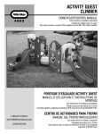
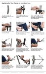
MODEL NO.
GS-W1001-1
SINGLE MAST NET CLIMBER
INSTALLATION MANUAL
Safety Checklist after first assembly
● Test intervals of Safety: 6 months
● Test Component and contents:
1. Removing the reticulated system:
- Check of removing condition each rope
- Screwing the turn buckle and conversion the turnbuckle
in anchors plate(see for this workstep turnbuckle assembly)
2. Abrasion condition of rope:
- Checking of all rope surface
- Strengthned of rope: Coating on the surface
3. Attachment condition of the anchors plate and turnbuckle
4. Screwing condition of all bolt
5. Galvanizing condition of the steel component:
- Protection of steel component from corrosion.
● Measure
In case of the appearance the defect detail is
repaired usually within 3 days after checking.
SHINHEUNG ENG
1046-3, Najeon-ri, Saengnim-myeon,
Gimhae-si Gyeongsangnam-do, 621821, Republic Of Korea
Tel) +82. 55. 326. 9096~7
Fax) +82. 55. 326. 9022
E-mail) [email protected]
Web site) www.gsweb21.com
Ver. 070101
1
SINGLE MAST NET CLIMBER
INSTALLATION & MAINTENANCE INSTRUCTIONS
MODEL NO.
GS-W1001-1
Features
This series is a pyramid-style climbing structure made of steel-loaded
Nylon cables and comes protected against UV.
GS Web uses the highest steel content and the strongest connection
materials in the industry, including a steel-wire core in our edge ropes
and connection points crushed in place with over 75 tons of pressure to
ensure long life of the games and maximum safety for the children.
GS Web Nets help bring movement, balance, exercise and fun back into
the playground.
Ages: 3 to 8 years
Capacity: 27 children
Size: L: 15' 7" / 4.74m
W: 15' 7" / 4.74m
H: 10' 6" / 3.2m
Use zone: L: 25' 5" / 7.74m
W: 25' 5" / 7.74m
Figure-1: Completed Net
2
MODEL NO.
GS-W1001-1
SINGLE MAST NET CLIMBER
Safety area and Fall Height zone
Safety area
The requirements for space and safety clearances are taken from
BS-EN 1176-1 / ASTM-F1487 / CSA Z614
The use zone for stationary play equipment shall extend no less than
72 in. (1830mm) from all sides of the play structure.
Fall Height : (a) 3' 7" / 1100mm (from surface)
The Fall height on the external surface of a pyramid shaped space net
is the hightest point attainable within a horizontal distance of
(b) 44" / 1100mm
from the edge of the structure where a free fall to the protective surface
is possible.
This distance in based on the centre of gravity height of the maximum
(a)
user.
(b)
Imperial/Metric conversion
6' = 1830mm
11' = 3350mm
33' 11" = 10360mm
Figure-2: Install and safety area
3
SINGLE MAST NET CLIMBER
Foundation Information
MODEL NO.
GS-W1001-1
Foundation
Please refer to GS-W1001-1 drawing for exact installation dimensions
Figure-3: Foundation section view
Level Line
Finished
Finished ground
Grade
surface layer
P1
Figure-4 : Excavate enough
materials to allow for proper
depth of concrete footings
P2
Pole
Wet concrete
Dry concrete
(Optional)
P1 = Depth below finished Grade (12" / 300mm)
P1 = Depth below finished Grade (12" / 300mm)
P2 = Depth of concrete footing (27-½" / 700mm)
P2 = Depth of concrete footing (27-½" / 700mm)
Also ensure that there is enough
space to allow the frame to be
positioned properly.
Anchor wood support frame to
ground with pickets to prevent the
frame from moving while concrete is
poured and sets.
4
MODEL NO.
GS-W1001-1
SINGLE MAST NET CLIMBER
Foundation Layout
Figure-5: Concrete footing and Anchor plate layout
Note: Total distance from
front of block to front of
block is 21' 11" (6700mm)
200
100 100
4" 4"
Positioning Anchor plate on footing
[CF] 'L" anchor hole
Front edge of anchor plate must be installed
4" / 100mm from edge of concrete footing.
Imperial/Metric conversion
11' = 3350mm
15' 6" = 4738mm
Anchor Plate position
5
MODEL NO.
GS-W1001-1
SINGLE MAST NET CLIMBER
Concrete Foundation
Assemble wooden support frames *
7-⅞"
4 frames (39-½" / 1000mm L x 31-½" / 800mm W x 27-½" / 700mm H)
1 frame (24" / 600mm L x 24" / 600mm W x 27-½" / 700mm H)
7-⅞"
7-⅞"
7-⅞"
*Use ½" (min) plywood; not included in package
5-⅞"
NOTE: Use anchor plate as guide
for exact measurements.
(a)
(b)
(a) wood jig for Anchor plate
(b) wood support frame
for concrete
Figure-6: Wood support frame
6
MODEL NO.
GS-W1001-1
SINGLE MAST NET CLIMBER
Concrete Footing
[Concrete]
Pour concrete* into wooden support frame until flush to top edge
Allow 3-5 days for concrete to cure before proceeding to next step.
[concrete footing work]
Pour wet concrete in the wooden support frame
*Concrete is to be wet concrete with minimum 25 MPA / 3500PSI.
Figure-7: Concrete footing work
7
SINGLE MAST NET CLIMBER
Remove Wood Support Frame
MODEL NO.
GS-W1001-1
Remove wood support frame from dry concrete blocks
After concrete has cured enough, remove frame and replace soil in area
around footing to subgrade level
Figure-8: remove wood support frame
8
MODEL NO.
GS-W1001-1
SINGLE MAST NET CLIMBER
Anchor Plate Assembly
(a) Anchor Plate
Figure-9: concreted block clean threads of "L" anchor bolts
(b) Post plate
(b) Post plate
(a) Anchor Plate
Figure-10: Attach Anchor plate to footing
with flat washer, locking washer and nut.
9
MODEL NO.
GS-W1001-1
SINGLE MAST NET CLIMBER
Post Assembly
Post Assembly
Insert Post following nylon string
STEP-2
STEP-1
Nylon string
Figure-11: Find Nylon String
Figure-12: Insert Post
following Nylon string
NOTE: Remove string prior to placing cap on post.
10
MODEL NO.
GS-W1001-1
SINGLE MAST NET CLIMBER
Attaching Cap to Post
Place Cap on Post
Thread the mast through the net’s center (per diagrams below,
or following factory-installed guide string). Press the cap
(already attached to the top of the net) into the mast’s top end.
STEP-3
Figure-14: U-bolt assembly.
STEP-4
Figure-13: Insert Post
into the Center of Net.
Note: Rubber mallet
may be required to
insert cap into post.
Figure-15: Post cap assembly.
11
MODEL NO.
GS-W1001-1
SINGLE MAST NET CLIMBER
Safety rope Fixing
Safety Cable Attaching
Attach safety cable to anchor plates (A) (B) (C)
as shown in Figure 16.
(A)
(B)
Figure-17: Safety cable Assembly
After successfully preparing the net
and mast assembly, attach safety cable
with
M22 X L110 H/T BOLT to Anchor plate
as shown below
M22 X L110 H/T BOLT
(C)
(B)
(C)
(A)
Figure-16: Attach cable to (A) (B) (C)
12
MODEL NO.
GS-W1001-1
SINGLE MAST NET CLIMBER
Placing Post in Position
It is strongly recommended that 3-4 workers
lift the net into place.
[Working Process]
(A)
(B)
(C)
(D)
(E)
(B)
(E)
(D)
(C)
Figure-18: Centre Post
(A)
Figure-19: Safety cables attached
13
MODEL NO.
GS-W1001-1
SINGLE MAST NET CLIMBER
Stand Net up
After standing up the Net, Attach remaining safety rope
and Turnbuckles
Figure-21: Loosen Turnbuckle:
all the way (about 100mm),
leaving only 4 or 5 threads
attached
(F)
(B)
(E)
(D)
(C)
(A)
Figure-20: Stand Net up
(A)
(B)
(C)
(D)
(E)
(F)
14
MODEL NO.
GS-W1001-1
SINGLE MAST NET CLIMBER
Attaching Turnbuckle to Anchor Plates
Anchor plate + Turnbuckle
Figure-23: Turnbuckle assembly
(b)
(a)
(a)
(b)
Figure-22: Tightening Turnbuckles
NOTE: Make sure post is level before tightening and remains level during process.
(a) + (a)
Tighten Rope with Turnbuckles at the Same time
(b) + (b)
Tighten Rope with Turnbuckles at the Same time
15
SINGLE MAST NET CLIMBER
Tensioning & Maintenance information
MODEL NO.
GS-W1001-1
Maintenance information
Please tighten rope with Turnbuckle properly.
If you strain the net too much, it may cause damage.
It is also recommended that subsequent checks on tension
should be carried out at monthly intervals and adjusted as
required.
This will increase the overall longevity of the product.
Checking: 1 month
Refer to IPEMA and TUV maintance system.
After Net structure tension is completed, the net will
stretch slightly over the first four weeks of use.
Following this initial period, the net needs
to be fully re-tensioned by Turnbuckle
after 1 year.
Figure-24: completed Net
16
MODEL NO.
GS-W1001-1
SINGLE MAST NET CLIMBER
Anchor Plate Assembly
8
3
1
1:
2:
3:
4:
5:
6:
main post
7: H/T bolt,nut washer
1: main
post rope
7: H/T bolt,nut washer
multi
compound
8: U-bolt,nut,washer
multi compound rope 8: U-bolt,nut,washer
post2:cap
9: main post plate
post cap
main post
plate
turn3:buckle
10: 9:
L-anchor
bolt,nut,washer
4: turn
buckle
10:
L-anchor
anchor
shackle
11: Anchor platebolt,nut,washer
5: anchor
11: Anchor plate
shock
proof shackle
ring
6: shock proof ring
2
5
4
11
7
9
6
10
10
17
SINGLE MAST NET CLIMBER
Maintenance
MODEL NO.
GS-W1001-1
A weekly check of the activity net is recommended to ensure
that no acts of vandalism have damaged the rope.
Periodic checks on tension will assist in the durability
of the product.
18
SINGLE MAST NET CLIMBER
Maintenance
MODEL NO.
GS-W1001-1
A. General safety measures
On the playground there should be a sign(pictogram) giving the following information:
a) general emergency telephone number;
b) telephone number to contact maintenance personnel;
c) name of the playground;
d) address of playground; and
e) other relevant local information, if applicable.
The entry, exit and emergency paths to and from a playground, intended for use by the public and emergency services, should be accessible and
free of obstacles at all times.
NOTE Attention is drawn to local regulations.
B. Procedures
Defects that occur during operation and which put safety at risk should be corrected without delay. If this is not possible, the equipment should
be secured against use e.g. by immobilization or removal.
There should be written operational procedures covering the measures to be taken in the event of accidents, fire and the like.
Until unsafe equipment is repaired and released for use, access by the public should be prevented. Information about accidents brought to the
attention of the manager should be recorded on a form that includes the following details:
a) date and tie of accident;
b) age and sex of victim and clothing worn, Including footwear;
c) equipment involved;
d) number of children on site at the time of the accident;
e) description of accident;
f) injury sustained including part(s) of body affected;
g) action taken;
h) witness statements;
i) any subsequent equipment modification;
j) weather conditions; and
k) any other relevant information.
19
SINGLE MAST NET CLIMBER
Maintenance
MODEL NO.
GS-W1001-1
C. Routine maintenance
To reduce accidents, the owner or operator should ensure that an appropriate routine maintenance schedule is established, implemented and
maintained. This should take into account local conditions and the manufacturer's instructions that can affect the necessary inspection frequency.
The schedule should list the components to be maintained and should also give procedures for dealing with complaints and breakdowns.
The routine maintenance of playground equipment and surfaces should consist of preventative measures to maintain their level of safety,
performance and compliance with the relevant part(s) of EN 1176. Such measures should include:
a) tightening of fastenings;
b) re-painting and re-treatment of surfaces;
c) maintenance of any impact attenuating surfaces;
d) lubrication of bearings;
e) markig of equipment to signify loose fill finished surface level;
f) cleaning;
g) removal of broken glass and other debris or contaminants;
h) restoring loose fills to the correct level; and
i)maintenance of free space areas.
D. Corrective maintenance
Corrective maintenance should include measures to correct defects, or th re-establish the necessary levels of safety of the playground equipment
and surfaces. Such measures should include:
a) replacement of fastenings;
b) welding of welding repairs;
c) replacement of worn or defective parts; and
d) replacement of defective structural components.
E. Personal safety
Repairs during operation that could put the safety of maintenance personnel of the public at risk, should be avoided.
F. Equipment alterations
Alterations to parts of a piece of equipment or structure that could affect the essential safety of the equipment should only be carried out after
consultation with the manufacturer or a compete person.
20