1
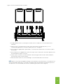
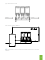
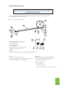
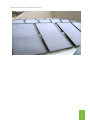
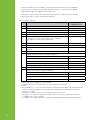
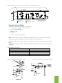
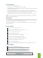
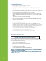
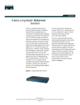
Installation Manual
SUMO Commercial Hot Water Systems
IMPORTANT INFORMATION AND WARNINGS
DANGER: Failure to operate the relief valve easing gear at least once every six months may result
in the water heater exploding. Continuous leaking of water from the valve may indicate a problem
with the water heater.
||
The power supply must be protected by an individual circuit breaker at the main electrical
supply switchboard and rated to suit the booster size.
||
The supply to the solar water heater can be operated directly from the switchboard or via a
remounted switch or time clock as requested by the customer.
||
The heater must be provided with a suitable means for disconnecting the power supply.
||
Appliance not intended for use by persons (including children) with reduced physical, sensory
or mental capabilities, or lack of experience and knowledge that prevents them from using the
appliance safely without supervision or instruction.
||
Children should be supervised by a person responsible for their safety to ensure that they do
not play with the appliance.
||
The Installation must comply with the requirements of AS/NZS 3500.4 & AS/NZS 3000, and
all local codes and regulatory authority requirements. In New Zealand, the installation must
conform to the New Zealand Building Code G12
Use of this Manual
This manual contains easy to follow, step-by-step
procedures for the correct assembly, installation,
and safe operation of both SUMO - Eternity Plus and
SUMO Pack systems.
Please take the time to read and understand the
complete installation requirements as this will ensure
a successful and trouble free installation. If you have
any questions regarding the installation process,
please contact your Chromagen Commercial
Solutions representative on
1300 367 565.
Other Chromagen Commercial Solutions
technical references for SUMO systems:
2
||
Hydraulic Manual
||
Operation Manual
||
Service Manual
Specifications are subject to change without notice. Images are for illustrative purposes only.
SUMO Eternity Plus systems
SUMO Eternity Plus manifolded gas water heaters provide a simple and economical solution to your commercial
water heating needs. The manifolding of multiple Eternity gas hot water units provides higher flow rates than
single units. These can be installed with staging valves to enable a systematic “light up” of each unit only
delivering hot water as required.
SUMO Eternity Plus systems are ideal for commercial applications of low, medium and high hot water demand.
SUMO Pack
SUMO Pack systems are pre-engineered and pre-manifolded modular systems combining continuous flow
hot water heaters & water storage, ideal for peak demand applications where large volumes of hot water are
required within a short period of time, such as morning and evening demands in apartment blocks and multidwelling developments. This combination of Eternity Plus gas water heaters plus hot water storage will deliver
volumes to suit a small apartment block up to a multi-storey high rise building using 15-20,000 litres of water in
the first hour delivery.
By including hot water storage you can improve the efficiency of your hot water system. Hot water storage
minimises the extent and frequency of gas or electric boosting and so uses less energy, in turn providing lower
operating costs.
SUMO Packs are available with a 2 to 6-unit Eternity Plus manifold system and one or more hot water storage
tanks to suit most common commercial applications, from low storage requirement up to very high volume
storage requirements. SUMO Packs are modular which means you can add storage tanks and units if
necessary to cope with higher demands as they eventuate (as in the case of building on or extending).
SUMO Pack Operation Overview
Cold water enters the storage tank by passing through an isolation and non-return valve from the mains water
supply. Cold water connects to the lower inlet of the storage tank and the other branch connects to the primary
pump. Cold water is drawn from storage tank to the inlet of the Eternity Plus manifold by primary circulation
pump. The Eternity gas water heaters will only operate when the pump is running.
The heated water from the Eternity gas water heaters then returns to the storage tank at the middle height of the
tank located above the cold inlet. Hot water comes from the top of the tank. This may be circulated around the
building and returned, via a ring main secondary pump to the cold manifold.
When there is a hot water draw-off, cold water enters the tank and pushes the hot water out of the tank towards
the outlet. When the temperature in the tank drops to 61 °C (the thermostat set point), the thermostat activates
the primary circulation pump(s). They draw water from the coldest part of the tank and circulate this through the
gas boosters. This water is then heated by the Eternity gas water heaters and returns to the tank heated. This
process is continued until the thermostat set point 65 °C is reached and the pump switches off.
The outlet temperature setting of the Eternity gas water heaters must be set at least 3 to 4 degrees higher than
the thermostat set point.
3
Index
1
Pre-installation Information6
2
SUMO System Dimension10
3
Assembly Instructions14
4
Mounting Solar Pre-heat Collectors
20
5
Location and Flueing28
6
Installation and Commissioning32
7
Maintenance and Warranty36
5
1.0
Pre-installation Information
7
SAFETY INFORMATION
Facts you need to know about the safe operation of your Chromagen water heater.
HOT WATER CAN BE DANGEROUS
Although Chromagen water heaters will generate hot water quickly and efficiently, all systems are
temperature controlled and under normal family use will operate between 60ºC and 70ºC. However,
water temperatures over 50ºC can scald skin and so care must be taken to ensure that injuries do
not occur through incorrect use of your water heater.
As required by the National Plumbing Code, a tempering valve MUST:
|| Be fitted to the heater to prevent the water temperature delivery at all sanitary outlets
exceeding a pre-set maximum (refer AS/NZS 3500.4).
||
Be connected to the hot water outlet lines.
||
Be fitted at the time of system installation or in retrofitting to existing systems
||
Be set by installing plumber as part of the commissioning process.
WARNING
HOT WATER BURNS. AS A SAFETY PRECAUTION, YOUNG CHILDREN SHOULD
NEVER BE ALLOWED TO OPERATE WATER HEATERS OF ANY TYPE.
Installation Standards
All Chromagen Solar Hot water systems must be installed by an authorised Plumber. All works must
conform with:
|| Local authority standards,
||
AS/NZS 3000
||
AS/NZS 3500.4
||
The National Plumbing Code
||
Local Electrical regulations.
Water quality
SUMO – Eternity Plus Systems
Chromagen “Open Loop” systems are suitable for use with water supplies with a total dissolved
solid content less than 1000 ppm and which the total hardness does not exceed 200 ppm CaCO3.
If the local water supply contains calcium hardness (CaCO3) exceeding 200 ppm, and an alkalinity
in excess of 150 ppm, then a Chromagen “Closed Loop” system is recommended.
8
Your local water authority can supply a water analysis if required.
Water Pressure
The hot water storage tank has a pressure / temperature relief valve set at 1000 kPa (850kPa in a
Themosiphon system). The cold water inlet pressure should not exceed 800kPa (650 kPa in the
Themosiphon system) which is 20% below the pressure relief valve setting.
SUMO Electrical connection requirements:
ALL ELECTRICAL CONNECTIONS MUST ADHERE TO LOCAL CODES AND
BE UNDERTAKEN BY A QUALIFIED ELECTRICIAN.
Single booster on storage tank (SUMO1)
|| 2 x 240v power supply leads
||
Primary circulation pump plugged into digital thermostat controlled power outlet
||
1 x 10 Amp GPO
Multiple booster units with a storage tank (SUMO2, 3, 4, 5, 6 etc)
|| Thermostat wired to pump switch on storage cylinder
||
Primary circulation pump plugged into digital thermostat controlled power outlet
||
1 x Separate 15 Amp GPO for Eternity continuous flow gas water heaters
Multiple Storage Cylinder Installation
|| Two or more systems joined together to create a single larger system
||
Connections as per multiple booster units stated above
Solar Pre-heating systems
|| 1 x 10 Amp GPO for solar controller
9
2.0
SUMO System Dimensions
Dimensions of Eternity Plus
Figure 1. Eternity Plus (Three gas booster) system.
(A)
Table 1. Installation specification of Eternity Plus
Model
12
A (mm)
Nominal Gas
Consumption (MJ/h)
Dry Weight
(kg)
Location
EP2
720
404
56
External
EP3
1080
606
74
External
EP4
1440
808
92
External
EP5
1800
1010
110
External
EP6
2160
1212
128
External
Dimensions of SUMO Pack
Figure 2. SUMO3 (Three gas booster) system with 300L tank
(A)
Table 2. Installation specification of SUMO pack
Model
A (mm)
Nominal Gas
Consumption MJ/h)
Dry Weight (kg)
Location
SUMO1
695
202
109
External
SUMO2
1570
404
137
External
SUMO3
1930
606
155
External
SUMO4
2290
808
183
External
SUMO5
2650
1010
201
External
SUMO6
3010
1212
219
External
13
3.0
Assembly Instructions
SUMO Frames
SUMO systems are supplied with rails that can be mounted to either a wall or a free-standing frame
system which suit most applications.
Wall mounting brackets are bolted to the frame and are usually fastened to a masonry wall behind the
unit. This method can be used where available to save space and provides excellent access to the
system.
Alternatively if there is no suitable structure to mount the rails on, a free-standing skid style base (fitted
with crane hooks) is available for securing to suitable structures beneath the skid. All systems must be
secured in accordance with AS/NZS 1170.2 and local regulations.
Assembly of an Eternity Plus System
||
Select the desired location for the Eternity gas continuous water heater making sure the final
position is in accordance with AS/NZS 5601.1:2010 clearances (Figure 14).
||
Locate and mount the first Eternity unit into position, ensuring the unit is level
||
Depending on the Eternity model being installed, continue to install each Eternity side-by-side until
all have been mounted (Figure 3)
||
Remove the manifold from packaging and ensure all is complete
||
Ensure all Eternity units are secure and level
||
Eternity units must be mounted at a minimum of 5mm between each one
Figure 3. Mount the units side by side
||
Starting from one end of the installed Eternity units, connect the relevant isolation valve supplied,
making sure the plastic washer (supplied) is in place before securing (DO NOT TIGHTEN – YET!)
||
Connect the opposite end of the manifold in the same way
|| Connect
16
either end first then all in between. Manifold supplied fully assembled
Figure 4. Connect the Eternity units to manifold
||
If adding additional units, you will require 3 x barrel unions to enable easy connection between the 2
manifolds
||
When you have connected all of the isolation valves to the bottom of the Eternity units, you can
systematically tighten all the connections (making sure not to over tighten)
||
Each manifold is supplied with a rapid rail that is connected to the manifold. This can now be secured to
the rear wall
||
Each manifold is also supplied with 3 x brass end caps. These can be used to cap off the opposite end of
the manifold that has been connected
||
Check system connections for leaks. Standard commissioning procedure should now be undertaken,
after which the system can be activated
||
When all isolation valves are connected and tight, secure mount brackets to the rear wall
NOTE: When hot and cold water supplies are being connected, please ensure the COLD is connected from one
end of the manifold and the HOT is connected to the opposite end of the manifold. This will ensure equal and
even pressure across the manifold. (This is known as balancing the system shown in Figure 5)
17
Assembly of SUMO Pack ||
Select the desired location for the Eternity units making sure the final position is in accordance
with AS/NZS 5601.1.2010 clearances (Figure 14)
||
Locate and mount the first Eternity unit into position, ensuring the unit is level
||
Depending on the SUMO Pack being installed, continue to install each Eternity unit side-by-side
until all have been mounted (Figure 3)
||
Remove the manifold from packaging and ensure all is complete
||
Starting from one end of the installed Eternity units connect the relevant isolation valve supplied,
making sure the plastic washer (supplied) is in place before securing (DO NOT TIGHTEN – YET!)
||
Then connect the opposite end of the manifold in the same way
||
If installing anything with more units than a SUMO3 you will be supplied with 3 x barrel unions to
enable easy connection between the 2 manifolds supplied
||
When you have connected all of the isolation valves to the bottom of the Eternity units, you can
systematically tighten all of the connections
IMPORTANT: DO NOT OVER TIGHTEN
||
Each manifold is supplied with a rapid rail that is connected to the manifold. This can now be
secured to the rear wall
||
The storage tank can be located remotely, either internally or externally
||
The location of the primary flow and return pump must be installed on the cold supply to the
Eternity units, ensuring the pump shaft is mounted horizontally
||
The primary circulation pump must be energised into the GPO supplied by the digital controller
||
The digital controller has been factory set to maintain a tank temperature of 65°C
||
Each manifold is also supplied with 3 x brass end caps. They can be used to cap off the opposite
end of the manifold that has been connected
||
Check system connections for leaks
||
Standard commissioning procedure should now be undertaken and system can be fired up
IMPORTANT: IF THE PUMP IS MOUNTED WITH THE SHAFT VERTICAL, THIS WILL VOID
THE PUMP WARRANTY.
18
Figure 5. Mount the brackets to the wall
Cold water
Hot water
Figure 6. Illustration of installation of SUMO Pack
NOTE: For illustration purposes only. Please seek advice from Chromagen Commercial solutions on actual system
requirements.
19
4.0
Mounting Solar Pre-heat Collectors
Standard (non-cyclone) Mounting Frames
In non-cyclonic areas a standard roof frame can be used to mount the solar collectors, these have been
engineered to mount the panels but are only suitable for installation in wind regions A and B. Please refer
to the instructions included with the kit for more details
1. Bolt both bottom angles #4 to the roof supports #5 with both bottom angles looking the same way.
2. Bolt the top angle #3 to the bottom angle #4 at the front with the top angle #3 facng the same way as the top angle #4 making sure the collector rail holes are on the top
3. Bolt the legs #6 on top of the bottom angle #4 and under the top angle #3 making sure the brace holes are positioned one top and one bottom
4. Bolt the Collector Rails top and bottom
5. Bolt the back brace #2 to the legs #6
6. Fit the collector/s and screw front and back
Items#
Length
Dimensions
Part Name
1
2
1050mm
50mm x 50mm
Collector Rail
2
1070mm
30mm x 30mm
Back Brace
1
3
2200mm
30mm x 30mm
Top Angle LONG
2
4
1950mm
30mm x 30mm
Bottom Angle (short)
2
5
1050mm
100mm 15mm 15mm
Roof Support
2
6
1000mm
30mm x30mm
Square Leg
2
-
25mm
-
Bolts
10
-
50mm
-
Bolts
6
-
-
-
Nuts, Washers, Rail Screws
16
Figure 7. Standard Mounting Frame
Front
22
Back
Quantity
Cyclone Mounting Frames
IMPORTANT: CYCLONE FRAMES MUST BE ASSEMBLED AND SECURED AS SPECIFIED
ON THE INSTALLATION INSTRUCTIONS INCLUDED WITH THE KIT. FAILURE TO DO SO
MAY RESULT IN SERIOUS INJURY.
Cyclone rated frames have been engineered and manufactured in accordance with AS/NZS 1170.2
and are suitable for installation in region C.
Figure 8. Cyclone Mounting Frame parts
1. Roof support 100 x 20 x 1.2 (x2)
2. Galv. Unistrut rails 40 x 20 x 1.2 (x2)
3. Collector rail (x2)
4. Collector Clamps (x2)
5. Tank straps (x2)
6. Unistrut M10 Bolts, Nuts & Washers (x6)
7. M10 Bolts, Nuts & Washers (x4)
8. Tank
9. Collector
10. Frame to battens fixings – refer to fixing details (8 fixings in total)
Notes:
1. Location of the unit to suit owner
2. Roof to be designed to carry 391 Kg (Total load of unit)
3. Maximum design uplift of 4.2 Kg per point
Limitations:
1. Max rafter spacing no greater than 900 C/C
2. Max height above ground permitted 5.0 m
3. Design for terrain category 2 ½
Wind Load Parameters
|| Up to Region ‘C’
||
(Tropical Cyclones)
||
Basic wind speed V2=57 m/sec – Vp=70 m/sec
23
Cyclone Mounting Frames Continued
Figure 9. Thermosiphon Mounting Frame parts
1. Roof support 100 x 20 x 1.2 (x2) L=1800
2. Galv. Unistrut rails 40 x 20 x 1.2 (x2) L=2800
3. Collector rail (x2) L=1000
4. Collector clamps (x2) L=1000
5. Tank straps (x2) L=1800
Figure 10.
24
Notes:
Minimum fixing requirements are M10Bolts to
be fixed through all components listed below
|| Collector clamp
||
Unistrut
||
Roof support
Fixing Cyclone Mounting Frames to a Support Structure
Figure 11
25
Thermosiphon Mounting Frames (for flat roofs)
1. Bolt the roof supports to the A Frames
2. Bolt the back brace to the A Frames
3. Fit and bolt the bottom collector rail to the A frames
4. Now position the collector on the frame and screw the front using the screws supplied.
5. Positin the Tank on the Frame allowing the tank to rest on the collector.
6. Using the back brackets and the strsps bolt the tank to the A frame
Items#
Length
Dimensions
Part Name
Quantity
1
2330
-
Frame
2
2
1000
50mm x50mm
Collector Rail
2
3
1170
30mm x30mm
Back Brace
1
4
1800
100mm x 20mm x 20mm
Roof Support
2
Figure 12. Thermisphon Frame
1860
Front
Back
Thermosiphon systems require specialised support when installed on to roof pitches below 10 degrees
from horizontal. These frames are designed to support the weight of not only the panels but also the
tank.
26
Figure 13. Solar collector array installed on a flat roof
27
5.0
Location and Flueing
Ensure reasonable access for installation, servicing and removal. All valves, controls and pumps
must be easily accessible. Tanks and frames must be mounted on a solid, level base capable of
supporting the weight of the appliance when full of water.
Eternity gas continuous flow water heater flue terminals must be located in accordance with AS
5601.1:2010 Fig 6.2 "Location of balanced flue terminals".
Table 3. Table of clearances
Ref.
Item
Ref.
Below eaves, balconies and other projections:
a
Fan assisted Minimum
clearances mm
Appliances up to 50 MJ/h input
200
Appliances over 50 MJ/h input
300
b
From the ground, above a balcony or other surface *
300
c
From a return wall or external corner *
300
d
From a gas meter (M)
(see Clause 5.11.5.9 for vent terminal location of regulator)
(see Table 6.6 for New Zealand requirements)
1000
e
From an electricity meter or fuse box (P)†
500
f
From a drain pipe or soil pipe
75
g
Horizontally from any building structure * or obstruction facing a
terminal
500
h
From any other flue terminal, cowl, or combustion air intake *
300
j
Horizontally from an open-able window, door, non-mechanical air inlet, or any other opening into
a building with the exception of sub-floor ventilation:
Appliances up to 150 MJ/h input*
300
Appliances over 150 MJ/h input up to 200 MJ/h input*
300
Appliances over 200 MJ/h input up to 250 MJ/h input*
500
Appliances over 250 MJ/h input*
1500
All fan-assisted flue appliances, in the direction of discharge
1500
k
From a mechanical air inlet, including a spa blower
1000
n
Vertically below an open-able window, non-mechanical air inlet, or any other opening into a building with the exception of sub-floor ventilation:
Space heaters up to 50 MJ/h input
150
Other appliances up to 50 MJ/h input
500
Appliances over 50 MJ/h input and up to 150 MJ/h input
1000
Appliances over 150 MJ/h input
1500
* Unless appliance is certified for closer installation.
† Prohibited area below electricity meter or fuse box extends to ground level.
NOTES:
1 Where dimensions c, j or k cannot be achieved an equivalent horizontal distance measured diagonally from the nearest discharge point of the terminal to the opening may be deemed by the Technical
Regulator to comply.
2 See Clause 6.9.4 for restrictions on a flue terminal under a covered area.
3 See Figure J3 for clearances required from a flue terminal to an LP Gas cylinder. A flue terminal is
considered to be a source of ignition.
4 For appliances not addressed above acceptance should be obtained from the Technical Regulator.
30
Figure 14. Horizontal flue terminal clearance (extract from AS/NZS 5601.1:2010)
Openable
window
h
j
n
c
I
j
T
e
c
e
h
Door
k
f
a
h
j
k
d
P
d
T
g
M
P
T
b
See note2
LEGEND:
T Flue terminal
I Mechanical air inlet
g
M
Gas meter
Electricity meter or fuse box
See note3
Shading indicates prohibited
areas for flue terminals
Flueing for Internal Models
The flueing system must be installed in accordance with:
|| The instructions supplied with the flue terminal
||
Local gas fitting regulations
||
Building codes
||
AS5601
||
Other relevant statutory regulations
NOTE: The flue terminal clearances in AS 5601 do not apply to Eternity gas continuous water heaters installed side-by-side. These appliances are AGA certified to be located side-by-side.
The flueing can be run in horizontal and vertical to a maximum of 12 metres, or with a maximum of three 90°
bends.
The table below shows the maximum vent length and bend numbers. Each continuous water heater is flued
individually.
Table 4. Maximum vent length
Number of 90° elbow
Maximum vent length
3
7.0 m
2
8.8 m
1
10.7 m
0
12.0 m
Figure 15. Vertical flueing installation diagram
Figure 16. Horizontal flueing installation diagram
31
6.0
Installation and Commissioning Instructions
Pre-install
||
Installation should only be performed by suitably licensed persons in accordance with AS/NZS
3500, AS/NZS 3000, AS/NZS 5601 and applicable local regulations.
||
Minimum and maximum pressures for gas and water must be observed.
||
Gas pressure range for optimal operation between 1.13 – 2.75kPa (NG); 2.75 – 3.5kPa (LPG)
||
Basic manifolding principles must be followed with water coming in one side of the manifold and
exiting from the opposite side, this allows for even flow of water through the system and ensures
all gas water heaters share the load.
Cold Water Supply
||
The COLD inlet of the tank required valves as to comply with AS 3500 and local regulations.
||
The inlet pressure is 500 kPa for maximum performance.
||
A Pressure Limiting Valve must be fitted if the cold water inlet pressure is in excess of 500 kPa.
Hot Water Outlet
||
The HOT water outlet pipe is a 32mm BSPT fitting on upper top of the storage tank. Isolation
valves are required.
||
Insulation/lagging must be fitted to all hot water piping to minimise heat loss.
Building Return Pump
||
Secondary or building return pumps may be installed in Eternity Plus & SUMO Pack systems.
||
Check valves must be fitted on the discharge.
||
The return line from the building hot water supply loop is connected back to the cold water supply
pipe after the check valve.
Gas Supply
||
Check gas type of the Eternity unit’s gas supply available on job (LPG or Natural).
||
The gas inlet is clearly marked on system.
||
Gas isolation valves are installed for each gas water heater.
||
Ensure the gas pipe sizing is adequate to deliver the required volume and pressure.
||
Refer to the pipe sizing charts in Appendix "F" AS/NZS 5601 for appropriate sized gas pipe.
||
Purge the gas pipe to ensure removal of debris and are etc prior to final connection.
||
Check for gas leaks with suitable instruction as per AS 5601.
Commissioning Instruction
||
All power to the system must remain off until the tank and water heater are completely full of water.
||
Purge the water inlet pipe to remove any debris before final connection to cold water inlet on
SUMO pack system.
||
Turn on the hot water tap to allow air to be removed while tank is filling with cold water, do not
bleed with PTR
34
||
Gently open the cold water valve on cold water supply.
||
Once tank is full, turn off the hot water tap.
||
Check all connections for water leakage. Tighten as required.
||
Purge gas lines until gas is available at all water heaters.
||
When the tank is filled, the primary circulation pump must be bled. Unscrew the silver bleed screw
on the side of the pump housing, allowing a few drops of water to escape and then tighten. Also
ensure the speed switch on the pump is set to 3.
Start up Instructions
||
Turn on all power to SUMO Pack (GPOs).
||
Green light on thermostat will illuminate when power is available.
||
When water in tank is below set temperature 60°C primary circulation pump should start. Water flow will
cause gas water heaters to start.
||
The output water temperature of gas water heater must be higher than the thermostat set point.
||
Thermostat will display temperature of water in tank. When it reaches the 65°C set point the pump and
gas water heaters will stop. The light on thermostat will not be lit when not operating.
||
Stabilised water and gas pressures must be recorded in the Maintenance log at the rear of this book.
NOTE: A commissioning checklist can be found in the Chromagen Commercial Solutions Service Manual for
SUMO Commercial Hot Water Systems.
Commissioning
Chromagen Commercial Solutions will provide a representative on request to attend the commissioning of
your commercial hot water installation. We will be present to provide an operational overview of the system and
advice on trouble-shooting, service tips and preventative maintenance.
Please follow the checklist below to ensure you have completed all necessary checks prior to operating the
system for the first time.
Installers Checklist
Check all connections are secure & correct.
Check that you have purged gas line of foreign materials.
Check hot & cold connections are correct.
Check you have turned the power on.
Check that you have turned on the cold water supply.
Check gas inlet pressure with the appliances operating.
Check that you have installed a solar approved tempering valve.
Check that the water temperature outlets are correct.
Check & clean cold water inlet filter.
Have you demonstrated / explained the operation of the system to the maintenance supervisor?
For Internal Models
Have you used Chromagen flueing components?
Does the flueing exceed 1.5m? If yes, are the dipswitches set correctly?
If flueing exceeds 1.5m have you installed a condensation trap?
IMPORTANT: IF GENUINE CHROMAGEN PARTS HAVE NOT BEEN
USED WARRANTY IS VOID.
35
7.0
Maintenance and Warranty
Preventative Maintenance
||
Inspect for damage, corrosion or water leaks on all items.
||
Check for leaks on the tank connections.
||
It is normal for PTR valve to operate during the heating cycle relieving pressure as the water is
expanding.
||
PTR valve should not exceed 1000 kPa. If it does, then a pressure reduction valve should be fitted
to the cold water inlet and must be 20% less than hot water PTR.
||
PTR valve may be operating if water temperature in tank is close to 95°C.
||
If pressure and temperature are low but valve is leaking, pull the lever for up to 10-15 seconds,
as foreign material may be jamming the valve seat. If valve fails to seat correctly, valve should be
replaced.
||
Thermostat is factory set and must not be tampered with.
||
Ensure the primary pumps are installed in a weather proof location. Wet pump electrics may cause
failure. Water can run along power lead so keep the lead looping under the pump and curving
upwards toward the electrical box.
||
Ensure shaft is horizontal.
||
DO NOT aim shaft upwards or downwards.
||
DO NOT locate terminal box under pump housing. Position it on top preferable or on side.
||
Bleed pump with chrome screw at end of pump casing. This will be facing towards you when the
pump shaft is horizontal. Pump runs on water bearing and is critical for life of pump. Excessive
noise indicates damage or air in the system which will require bleeding.
||
The screw removed the spinning/stationary impeller shaft can be inspected.
||
Ensure pump direction of flow arrow is towards Eternity units.
||
No flow: Check ball valves and any non return valve for correctly installed.
Maintenance and Service Calls
UNDER NO CIRCUMSTANCES SHOULD NON-QUALIFIED PEOPLE ATTEMPT TO
UNDERTAKE SERVICE WORK, AS THIS CAN VOID THE WARRANTY)
Should your SUMO hot water system not provide sufficient hot water please undertake the following
quick checks before requesting a service visit:
|| Check to make sure all isolation valves are in the “ON” position
||
Check to ensure the power supply is “ON”
||
Make sure there is sufficient gas to the gas water heaters
||
Make sure all the water inlet filters are free from debris
||
Ensure all gas filters are free from debris
||
Check the pump is plugged in and switched “ON” and pumping
FOR MORE INFORMATION ON SERVICING A SUMO SYSTEM PLEASE REFER TO THE CHROMAGEN
COMMERCIAL SOLUTIONS SERVICE MANUAL .
IF THE SYSTEM IS STILL NOT OPERATING ORRECTLY, CALL YOUR LOCAL CHROMAGEN SERVICE
OFFICE ON: 1300 36 75 65
38
Chromagen Commercial Solutions Maintenance Services
Ask us about a scheduled maintenance service. Chromagen Commercial Solutions can develop a regular
service and maintenance program for your commercial hot water or solar electricity installation that provides
preventative maintenance and timely response to faults to ensure long service life and best operational
efficiency.
Warranty
Product
Commercial Warranty
HOT WATER
Eternity (Heat exchanger)
5 Years
Tanks (Enamel)
5 Years
Flat Plate Solar Collectors
7 Years
Evacuated Tube Solar Collectors
1 Year
Circulation Pumps
1 Year
All other parts & Labour
1 Year
Chromagen shall provide both the labour and the parts required to repair, or, at Chromagen's option,
Chromagen shall replace any part of the system which upon examination by Chromagen is determined by
Chromagen to have been defective during the applicable warranty period. The replacement component shall
carry the balance of the original warranty period.
The water heater must be installed in accordance with Chromagen's installation instructions along with relevant
local and statutory requirements. Damage to buildings, chattels or any other consequential damage caused
either directly or indirectly due to leakage of the water heater and breakage of collector glass due to vandalism
or storms including hail are not within the scope of this warranty.
For full details of our Terms and Conditions please refer to the Chromagen website at chromagen.com.au.
39
CNF0067 032012
Chromagen Pty Ltd | chromagen.com.au | [email protected] | 1300 367 565
VICTORIA | NEW SOUTH WALES | QUEENSLAND | NORTHERN TERRITORY | WESTERN AUSTRALIA | SOUTH AUSTRALIA