1
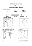
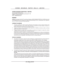
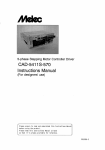
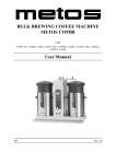
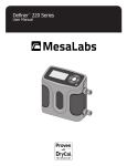
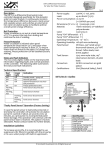
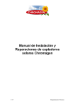
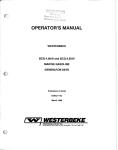
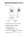
Service Manual
SUMO Commercial Hot Water Systems
1
IMPORTANT INFORMATION AND WARNINGS
DANGER: Failure to operate the relief valve easing gear at least once every six months may
result in the water heater exploding. Continuous leaking of water from the valve may indicate a
problem with the water heater.
||
The power supply must be protected by an individual circuit breaker at the main electrical
supply switchboard and rated to suit the booster size.
||
The supply to the solar water heater can be operated directly from the switchboard or via a
remounted switch or time clock as requested by the customer.
||
The heater must be provided with a suitable means for disconnecting the power supply.
||
Appliance not intended for use by persons (including children) with reduced physical,
sensory or mental capabilities, or lack of experience and knowledge that prevents them
from using the appliance safely without supervision or instruction.
||
Children should be supervised by a person responsible for their safety to ensure that they
do not play with the appliance.
||
The Installation must comply with the requirements of AS/NZS 3500.4 & AS/NZS 3000, and
all local codes and regulatory authority requirements. In New Zealand, the installation must
conform to the New Zealand Building Code G12
Use of this Manual
The SUMO Commercial Hot Water Systems Service
Manual is designed to give commercial and installing
plumbers aid in the diagnosis of system problems and
instruction in the repair of system components. Please
read this manual carefully and in full, so that you
understand how to trouble shoot a SUMO system and
to ensure timely maintenance and service.
If you have any questions regarding the installation
process, please contact your Chromagen Commercial
Solutions representative on
1300 367 565.
Other Chromagen Commercial Solutions
technical references for SUMO systems:
||
Hydraulic Manual
||
Installation Manual
||
Operation Manual
Specifications are subject to change without notice. Images are for illustrative purposes only.
Index
1
Standards References4
2
Installation and Commissioning Instructions
8
3
Servicing Safety Devices and Anodes
12
4
T-Series Eternity Gas Booster16
5
The A419 Control Thermostat
22
6
Grundfoss UPS Series Pumps and Screen Filters
30
7
Kanitti Solar Controller34
8
Trouble Shooting and Warranty38
3
1.0
Standards References
AS/NZS 3500.4:2003
||
Details the minimum standard for installation, alteration or repair of domestic hot water systems.
||
States the requirements of minimum storage temperature and maximum delivery temperature for
hot water systems as follows:
Clause 1.9 Water Temperature
1.9.1 Storage temperature. Hot water shall be stored at a minimum of 60°C to inhibit the growth of legionella bacteria.
1.9.2 Sanitary fixtures delivery temperature. All new hot water installations shall, at the outlet of all sanitary fixtures used primarily for personal hygiene purposes deliver hot water not exceeding:
||
45°C for early childhood centres, primary and secondary schools and nursing homes or similar
facilities for young, aged, sick or disabled persons;
||
50°C in all other buildings.
NOTE: Compliance with these temperature limits is optional for kitchen sinks and laundry tubs.
Individual States or bodies may have their own requirements in addition to, or
In excess of, above, this is the minimum requirements under the standards.
To meet this requirement Chromagen commercial hot water heaters are set to a higher temperature and
a tempering or thermostatic mixing valve must be fitted for fitted for warm water delivery to these areas.
Various State Authorities have their own requirements for the provision of water to areas used primarily
for personal hygiene. Consult your local authority for any specific requirements in the State or area
where the system is to be installed.
AS/NZS 3498:2009
||
States that means shall be provided to inhibit the growth of Legionella bacteria in potable water
within the water-heating appliance. A water-heating appliance will be deemed to comply with this
requirement if it satisfies the following requirement:
The water heater is operated such that all water is subjected to a temperature dependent minimum exposure period as specified in Table below within 7 days before passing through the water-heating appliance’s heated water outlet.
Standards References
Table 1 Minimum exposure period
6
Temperatures
Minimum exposure period
70°C or greater
1 second
66°C
2 minutes
60°C
32 minutes
55°C
6 hours
7
2.0
Installation and Commissioning Instructions
Pre-install
||
Installation should only be performed by suitably licensed persons in accordance with AS/NZS
3500, AS/NZS 3000, AS/NZS 5601 and applicable local regulations.
||
Minimum and maximum pressures for gas and water must be observed.
||
Gas pressure range for optimal operation between 1.13 – 2.75kPa (NG); 2.75 – 3.5kPa (LPG)
||
Basic manifolding principles must be followed with water coming in one side of the manifold
and exiting from the opposite side, this allows for even flow of water through the system and
ensures all gas water heaters share the load.
Cold Water Supply
||
The COLD inlet of the tank requires valves to comply with AS/NZS 3500 and local regulations.
||
The inlet pressure should be 500 kPa for maximum performance.
||
A Pressure Limiting Valve must be fitted if the cold water inlet pressure is in excess of 500 kPa.
Hot Water Outlet
||
The HOT water outlet pipe is a 32mm BSPT fitting on upper top of the storage tank. Isolation
valves are required.
||
Insulation/lagging must be fitted to all hot water piping to minimise heat loss.
Building Return Pump
||
Secondary or building return pumps may be installed in Eternity Plus & SUMO Pack systems.
||
Check valves must be fitted on the discharge.
||
The return line from the building hot water supply loop is connected back to the cold water
supply pipe after the check valve.
Gas Supply
||
Check gas type of the Eternity unit’s gas supply available on job (LPG or Natural).
||
The gas inlet is clearly marked on system.
||
Gas isolation valves are installed for each gas water heater.
||
Ensure the gas pipe sizing is adequate to deliver the required volume and pressure.
||
Refer to the pipe sizing charts in Appendix "F" AS/NZS 5601 for appropriate sized gas pipe.
||
Purge the gas pipe to ensure removal of debris prior to final connection.
||
Check for gas leaks
Installation and Commissioning Instructions
Commissioning Instruction
10
||
All power to the system must remain off until the tank and water heater are completely full of
water.
||
Purge the water inlet pipe to remove any debris before final connection to cold water inlet on
SUMO pack system.
||
Turn on the hot water tap to allow air to be removed while tank is filling with cold water, do not
bleed with PTR
||
Gently open the cold water valve on cold water supply.
||
Once tank is full, turn off the hot water tap.
||
Check all connections for water leakage. Tighten as required.
||
Purge gas lines until gas is available at all water heaters.
||
When the tank is filled, the primary circulation pump must be bled. Unscrew the silver bleed
screw on the side of the pump housing, allowing a few drops of water to escape and then
tighten. Also ensure the speed switch on the pump is set to 3.
Start-up Instructions
||
Turn on all power to SUMO Pack (GPOs).
||
Green light on thermostat will illuminate when power is available.
||
When water in tank is below set temperature 65°C primary circulation pump should start. Water flow
will cause gas water heaters to start.
||
The output water temperature of gas water heater must be higher than the thermostat set point.
||
Thermostat will display temperature of water in tank. When it reaches the 65°C set point the pump
and gas water heaters will stop. The light on thermostat will not be lit when not operating.
||
Stabilised water and gas pressures must be recorded in the Maintenance log at the rear of this book.
NOTE: A commissioning checklist can be found in the Chromagen Commercial Solutions Service Manual for
SUMO Commercial Hot Water Systems.
11
3.0
Servicing Safety Devices and Anodes
Safety Devices
This hot water system is supplied with various safety devices including, Pressure & Temperature
Relief Valves (PTR), Consolidated Safety Valve, temperature sensors and overheat sensors.
These devices must not be removed, obstructed or tampered with in any way that may affect the
operation of the safety device. These devices must be installed as required and be tested at the
time of commissioning and under a regular maintenance program to ensure safe operation of the
system.
Pressure Temperature Relief Valve (PTR)
This valve is located at the top of each tank. It is normal for a small amount of water
to be discharged. Your system is fitted with a 1000kPa PTR, please ensure that the
water pressure is maintained at a maximum of 80% of this value to minimise excessive
water discharge. It is recommended that the easing lever be actuated every six months
to prevent the accumulation of mineral deposits that may impair valve operation. The
easing lever should be operated smoothly as a sudden influx of water may damage the
valve. The drain line must be compliant with AS3500
Consolidated Safety Valve (If fitted)
A consolidated safety valve may be fitted to the primary tank. This device is designed
to release any steam that may form during sudden pressure drops within the system.
This valve should be inspected regularly and maintained in accordance with the valve
manufacturers recommendations.
Expansion Control Valve (If fitted)
An expansion control valve may be fitted in the cold water supply line to the water
heater, it may discharge a small quantity of water instead of the PTR valve on the water
heater. The benefit is that energy is conserved as discharged water is cooler. If this
leaks continuously it can indicate high pressure in the tank and may require a pressure
limiting valve to be fitted.
Anode replacement
Servicing Safety Devices and Anodes
The anode in the Chromagen hot water tanks is located on the flange plate assembly at
the top of the tank. To inspect or replace the anode:
1. Disconnect water supply and remove pressure
14
2.
Open PTR to ensure pressure is relieved
3.
Remove covering cap at top of tank
4.
Unbolt top flange plate, removing all flange and lifting bolts
5.
Remove flange
6.
Replace anode if required
7.
Inspect tank seal and replace if required
8.
Re-install flange in reverse order as described above
9.
Test for leaks
Flange bolt
Anode bolt
Lifting bolt
Flange plate
Electric Element & Thermostat (if present)
Ensure power is turned on and available to the thermostat. Check thermostat for thermal overload, test rest
and inspect for cause of potential electrical overload. If power is present and can be measured across output
terminals of thermostat, measure resistance of element to determine possible source of fault.
Replacement of electric element:
1.
Disconnect power from system
2.
Disconnect water supply and remove pressure
3.
Open PTR to ensure pressure is relieved
4.
Remove covering cap at top of tank
5.
Unbolt top flange plate, removing all flange and lifting bolts
6.
Remove flange
7.
Replace element if required
8.
Inspect tank seal and replace if required
9.
Re-install flange in reverse order as described above
10.Test
for leaks
Thermostat testing
1.
Disconnect power from system
2.
Turn red dial up/down until click of bi-metallic strip is heard
3.
At point of click measure temperature
4.
Measure tank temperature
5.
If tank temperature and thermostat temperature do not correspond calibration
may be required, otherwise jump to step 10
6.
Remove black plastic cap from thermostat
7.
Using brass spline shaft adjust to point of activation of the metallic strip (clicking)
8.
Set red dial on black cover to temperature of system
9.
Refit black cover
10.Test
to ensure click occurs at point of corresponding temperature
11.Disconnect
element and turn thermostat to minimum
12.Measure
resistance terminals 1-3 should be short circuit
13.Measure
resistance terminals 2-4 should be short circuit
14.Reconnect
element
15.Reconnect
power
16.Test
operation
17.Disconnect
power and replace thermostat if required
15
4.0
T-Series Eternity Gas Booster
Figure 1. Eternity T-Series Parts
Table 2 Parts list
T-Series Eternity Gas Booster
No. Description
18
No.
Description
No. Description
1
Front Panel
11
Thermal Fuse Device
23
Water Control Valve
2
Outer Casing
12
Combustion Chamber
24
Remaining Flame Safety De.
3
Exhaust Flue
13
Fan Motor Assembly
25
Manifold
4
Modulation Valve Unit
14
Burner Assembly
26
Drain Knob
5
P.C.B. Unit Assembly
15
Cable Access
27
Ignition Spark Electrode
6
Igniter
16
Frost Sensing Switch
28
Flame Sense Electrode
7
Incoming Water Temp.
Thermistor
17
Water Flow Sensor
29
Transformer (240V)
18
Heat Exchanger
8
Water Inlet
19
Gas Inlet
9
Hot Water Outlet
20
Exhaust Chamber
10
Outgoing Water Temp.
Thermistor
21
Pressure Relief Valve
22
Anti-frost Heater
Figure 2. Eternity T-26 Block diagram
19
Figure 3. Eternity T-Series Wiring diagram
Takagi dip switch setting pattern
DIP SWITCH
PATTERN
T-Series Eternity Gas Booster
7
8
60°C
75°C
H
45°C
ON
ON
OFF
55°C
OFF
OFF
OFF
60°C
ON
OFF
OFF
75°C
OFF
ON
OFF
80°C
-
-
ON
PATTERN
20
6
DIP SWITCH
1
2
LPG
ON
OFF
NATURAL
OFF
ON
3
4
ON
OFF
Table 3 and 4 Eternity T-Series wiring information
Check Point
Mark on
Electric Diagram
Normal Range
Colour/Number of Wire
A
Light blue(3) - blue at COM
DC80 ~100V / 0.8~1.7kΩ
A
green(9)
DC80 ~100V
A
orange(53) - blue at COM
DC80~100V
A
red(73)
DC80~100V
A1
blue - blue
DC1V & less / 1.3Ω & less
A2
blue - blue
DC1V & less / 1Ω & less
B
red - blue
DC110~160V
B
yellow - blue
DC110~160V
B
orange - blue
DC2~6.5V
B
white - blue
DC3~12V (4000Pulse/min & more)
C1. C2
black - black
10°C12~18kΩ 60°C2.2~2.7kΩ
D
red(+) - black(-)
DC4.0~5.5V
D
white(85) - black(-)
DC1~4V (1080Pulse/min)
E
white - black
DC11~25V
F
red - black
DC7~16V / 0.09~0.2kΩ
G
white - red
DC1~10V / 30~51Ω
H
orange(17) - green(18)
DC -10~100V
H
yellow - green(18)
DC -0.2~ -5V
I
purple(7) - purplt(7)
AC90~110V
J
white - black
AC90~110V
- blue at COM
- blue at COM
Light of LED on
Main P.C.B.
Remote
Control
Fault
Possible region of error
Blinking One time
031
Fault of Gas Selection Switch
Gas Selection Switch
701
Fault of PCB
Main PCB
Fault of loading circuit on
PCB for Proprtional valve
Proprtional valve
311
Disconnection/Short circuit
of Hot water outlet Thermistor
Hot water outlet Thermistor
321
Disconnection/Short circuit
of Cold water inlet Thermistor
Cold water inlet Thermistor
Blinking Two times
391
Fault of Air-fuel Ratio Rod
Air-fuel Ratio Rod
CL
Continue to opened the tap
Bath fill switch
111
Fault of Ignition
Main PCB, Igniter, Flame rod,
Thermal fuse, Remaining Flame
Safety Device
121
Lost of Flame
Solenoid or other part of Gas
circuit
510
Fault of drive circuit for Main
Solenoid
Main Solenoid , Main PCB
511
Fault of drive circuit for
Solenoid Valves
Solenoid Valves, Main PCB
721
Fault of Pre-check
Main PCB, Flame rod
991
Imperfect Combustion
Exhaust flue, Air inlet, Test point
gas pressure, Heat Exchanger
Blinking Four times
611
Irregular fan speed
Fan motor or Main PCB
Blinking Five times
101
Warning for 991 Error Code
Exhaust flue, Air inlet, Test point
gas pressure, Heat Exchanger
Blinking Three times
21
5.0
The A419 Control Thermostat
The Johnson A419 control is a Single-Pole, Double-Throw output relay. The control features a
lockable three button touch pad for set-up and adjustment, and a liquid crystal display (LCD)
which displays the sensed temperature and other control functions.
A front panel light emitting diode, (L.E.D.) indicates the output relay status. When the relay contact
is energized and the thermostat contacts close, the LED will be illuminated.
The control fitted to the SUMO cylinder is factory set to a set point temperature of 65°C, unless an
alternative temperature has been specified for a specific job.
When the power is turned on to the thermostat, the digital display should scroll through and settle
on the temperature reading of the water within the storage cylinder.
As water is heated, the display temperature will increase to indicate current temperature of water
within the cylinder.
Set-point (SP)
The set-point establishes the temperature value at which the equipment will be switched on or off,
depending on the user selected mode of operation. Set-point range can be set from -34 to 100°C,
in one degree increments.
The set-point mode in Chromagen systems is set to cut-out, the set-point is the temperature at
which the (N.O.) contacts will open. For the SUMO, this cut out set-point is normally 65°C.
Differential (diF)
The differential establishes the difference in temperature between the cut in value and the cut out
value.
The difference is set relative to the set-point and may be between 1°C to 30°C.
For the SUMO, this setting is the same as the factory default setting of 4°C.
Anti-Short Cycle Delay. (ASD)
The Anti-Short Cycle Delay establishes the minimum time that the output relay remains deenergized before the next on-cycle. The ASD does not allow the output relay to re-energize until
the programmed time delay has elapsed. The delay is activated when the control is first turned on
and every time an on cycle ends. When the display is activated, the LCD alternatively flashes the
sensor temperature and the ASD. The ASD range is 0 to 12 minutes in one minute increments. For
the Chromagen systems, the ASD setting is 0 minutes.
Temperature Offset (OFS)
The OFS establishes a set secondary Set-point and Differential values that may be invoked to
The A419 Control Thermostat
control an application where the circuit is closed between the Binary input (BIN) and Common
(COM) terminals ( and BIN appears on the display) Offset range is 0°C to 50°C (in one degree
increments).
A typical application might use a switching time clock to involve night-setback temperature
settings. For the Chromagen systems, this function is not utilized.
24
Settings & Adjustments
The Johnson A419 Temperature Controller is ‘locked‘ at Chromagen to a set temperature. Adjusting the UP &
DOWN buttons will have no effect on the thermostat. On normal servicing & fault finding, there is no need to
adjust the thermostat. If ordering a new/replacement Johnson A419 temperature control as a spare part, the
control will need to be correctly set to suit the SUMO system.
The touchpad cannot be unlocked without a jumper installed across the P5 jumper pins. Do not discard jumpers
in case they are required in the future
Positioning the Jumpers
||
The P5 jumper position determines if the touchpad is locked or unlocked.
||
The P4 jumper pin block has two pairs of jumper pins. The top pair of pins (JUMP1), determines if the
control is set for heating or cooling mode. The bottom pair of pins, (JUMP2) establishes whether set point
is at cut in or cut out.
NOTE: Make sure the Touchpad Lock jumper is installed (Unlocked)
before
attempting to adjust
Touchpad
Touchpad
Heatingthe
Mode
Locked
A419 control functions.
Figure 4. Positioning the Jumpers
Unlocked
Cut-in at Setpoint
Figure 5. Jumper Positions & Control Settings
Cooling Mode
Cut-in at Setpoint
JUMP1
JUMP2
=
Jumper
Installed
(Jumper Positioned on Both Pins)
P5
P4
Touchpad Touchpad
Locked Unlocked
=
Pins
Jumper
JUMP1
=
Removed
(Jumper Positioned on One Pin)
Installed
(Jumper Positioned on Both Pins)
P5
JUMP2
P4
Cooling Mode
Cut-in at Setpoint
Cooling Mode
(Standard)
Cut-out at Setpoint
Heating Mode
(Standard)
Cut-out at Setpoint
=
Pins
Heating Mode
Cut-in at Setpoint
Heating Mode
(Standard)
Cut-out at Setpoint
Cooling Mode
(Standard)
Cut-out at Setpoint
Removed
(Jumper Positioned on One Pin)
Jumper Designations, Jumper Positions and Control Settings
Function
Jumper Pins Designation
on Control
Setting
Jumper Position
Operating Mode
JUMP1
Top pair of pins on Block P4
Heating Mode
Installed
Set Point
JUMP2
Bottom pair of pins on Block P4
Set-point at Cut Out
Installed
Touch Pad Lock
P5
Locked
Removed
Unlocked
Installed
25
Changing the A419 Control Temperature Units
||
The A419 control is factory set to display Fahrenheit temperature. To change to Celsius, press the
two arrow buttons simultaneously.
||
UP and DOWN arrows simultaneously.
||
Press UP & DOWN arrows simultaneously again to return to a Fahrenheit temperature.
||
Verify that the control is displaying the desired temperature units before setting the set-point.
Setting the A419 Control Set-Point
To view & adjust set-point:
|| Press and hold MENU (about 2 seconds) until the display flashes ‘SP’
||
Press MENU again to display existing set point value.
||
Press UP or DOWN arrows to change set-point value. (Typically 65°C)
||
Press MENU again to save new value. The display will now return to the sensed temperature.
LCD
UP/ DOWN
ARROWS
LED
NOTE: If no set-up entry is made for 30 seconds, the control reverts to (normal) temperature display.
Setting the other A419 Control functions
The A419 Control Thermostat
To set the Differential, Anti sort cycle display, Temperature offset or Sensor failure operation,
use the following method:
26
||
Press and hold MENU until display changes to flashing ‘SP’. (Normally takes about 2 seconds)
||
Press UP or DOWN arrows repeatedly until the desired function is displayed. (see table below)
||
Press MENU to display the functions current value.
||
Press UP or DOWN arrows until the desired temperature is displayed.
||
Press MENU to save the new value. The display will then return to the sensor temperature.
NOTE: If MENU is not pressed after changing the setting, the new setting will not be saved and the
control will revert to the previously programmed setting values.
Table 5 Control function displays
Display Symbol
Function
Control
Range – Units/Value
Range – Units/Value
SP
Set Point
-34 to 100°C
diF
Differential
1°C to 30°C in 1 degree increments
ASd
Anti-short cycle
0 to 12 – (in one minute increments)
SF
Sensor Failure Operation
(No range) 0 = output relay de-energised
1 = output relay energised
F or C
Temperature Units
(No range) - °F or °C
Flame Symbol
Heating Mode
Heating (flame symbol) is displayed when JUMP1
jumper is installed
NOTE: Do not set the Set-point and Differential values, which (when their values are totaled), fall outside the A419
control’s set-point range (–34°C to 100°C). The control will not function properly if the Cut In or Cut Out values
are outside the control set-point range.
If no setup entry is made for 30 seconds, the control reverts to the normal temperature display.
Any saved A419 control settings are non-volatile and remain in the controller’s memory during power
interruptions.
CAUTION – RISK OF ELECTRIC SHOCK
Hazardous voltages may be present at electrical terminals and other exposed internal
metal surfaces. Do not touch any metal parts within the control when cover is removed.
Any contact with metal parts including with metal conductive tools may result in serious
injury or death.
Testing if power is available to thermostat:
1.
Remove lower cover panel from storage cylinder
2.
Remove the four (4) screws securing the cover of Johnson controls thermostat
3.
Carefully lift up cover. Cover is attached by wiring to PCB inside thermostat, so cover cannot be removed,
only moved
4.
Check for 240 volt power supply on supply terminals located under card cover
Testing if power is available to common terminal on thermostat:
1.
Check 240VAC power is available on thermostat common terminal
Testing if thermostat contacts have closed:
1.
Once temperature displayed on thermostat is less than set temperature, check for 240 VAC available on
terminal supplying voltage to primary pump and neutral.
2.
If contacts have not closed, thermostat is faulty. Replace thermostat
Repairs & Replacement
Do not attempt to repair or recalibrate the Johnson A419 temperature control. In the case of a defective or
improperly functioning control, the control will require replacement.
27
Figure 6. Wiring Diagram for Johnson Controller
Common
Sensor
N
A
E
240V AC Supply
The A419 Control Thermostat
GPO
28
Testing to see if temperature probe is working correctly:
1.
Disconnect all power sources to the control
2.
Remove the lower cover panel from the storage tank
3.
Remove four screws from the cover panel on the Johnson controller
4.
Carefully lift up cover. Note: cover is attached by wiring to PCB inside thermostat, so the cover cannot be
re-moved, only moved to one side.
5.
Using a thermometer, take a temperature reading at the sensor location
6.
Disconnect sensor from control
7.
Check resistance of temperature probe, across the two wires
8.
Check measured value conforms to table below
9.
If temperature measured resistance value is substantially different from the expected value for that
temperature, replace controller assembly (PT no MK0005)
Graph 1. Thermostat resistance vs. temperature
Temperature ( °F)
260
240
220
200
180
160
140
120
100
80
60
40
20
0
-20
-40
Temperature ( °C)
120
100
80
60
40
20
0
-20
-40
500
700
900
1100 1300 1500 1700 1900 2100
29
6.0
Grundfoss UPS Series Pumps
and Screen Filters
Grundfoss Pumps
Pump orientation
Care should be taken to ensure correct orientation of the pump. The control box should be on the
upper surface to prevent water entry. Pump speed should be set to speed III (3) and pumps should be
regularly used. Failure to circulate water through the pump may result in premature failure and result
in the pump seizing due to mineral deposits within the water. Your Chromagen system is designed to
ensure the pumps are regularly circulated to avoid this, but disconnection or decommissioning of the
system must include draining of the pump assemblies.
The pump should always be bled using the screw on the front of the pump motor assembly as seen
above. Noises and scraping sounds should be investigated to avoid failure of bearings or impellor
mechanism.
Bleeding Air from Primary Pump
Grundfoss 20-60B & Grundfoss 32-80N:
1. Turn on power supply to pump
2.
Make sure the speed selection switch is on 3
3.
Unscrew (counter clockwise) end cap in motor
4.
Allow air & water to dribble out of bleed hole
5.
When all air is bled through, re-place end cap in motor
6.
Check for water leaks
Check power is available to the primary circulation pump:
1. Plug pump into known good 240V AC supply and test operation.
Grundfoss UPS Series Pumps and Screen Filters
2. Free impeller if seized, replace pump if impeller is dislocated from the motor drive shaft.
32
3. Replace pump if required.
4. Ensure pump is correctly primed, prior to use and that all air is bled through.
CAUTION
If hot water system has been operating, the water being bled from the pump could be
very hot.
Do not locate the electrical connection & speed selection switch underneath the pump
body
Maintenance Instructions for Manual Screen Filter
The screen filter bodies are fabricated from mild steel, and finished corrosion resistant baked on polyester
coating.
To install the filter mount the inlet and outlets with the water flow going in the correct direction.
A pressure gauge or indicator could be fitted across the inlet and outlet to indicate the condition of the filter.
1
1 - Cover
2 - Body
3 - Outer screen element
4 - Inner screen element
5 - Pressure measuring port
3
2
6 - Flushing valve
4
5
6
To clean the screen element, follow the following sequence:
1. Isolate the filter and de-pressurise any pressure remaining in the system.
2.
Unscrew the T-clamp handle and remove the clamp bar from it’s mounting holes.
3.
Remove the lid of the filter.
4.
Remove the filter element from the filter.
5.
Clean the screen element with a pressure hose.
6.
With disc elements the clamp nut inside the end of the disc pack needs to be fully loosened to release
and expand the discs so that a hose can easily clean the element.
7.
Clean the element thoroughly and replace.
8.
Reassemble the filter lid and clamp in opposite sequence to disassembly making sure that the end
seals are in correct position. Do not over tighten cap!
The cleaning frequency of the filter will depend on a number of factors including: The volume of suspended
solids in the water, the flow rate, the particle sizes and the aperture of the screen in the filter.
Our inline one or two-stage filters are designed for use in agricultural, industrial and public sector/municipal
environments, either as control filters or as main filters.
Our Manual Screen Filters standard features include:
||
Inlet/outlet on axis of 90 degrees for type 100 and 180 degrees for type 200
||
Inlet and outlet through quick coupling, threaded, or flange connectors electrostatically oven-cured
with polyester powder at 150 micron thickness or heat galvanized at 100 micron thickness
||
Double element filters (optional) available in micron sizes of 60, 80, 100, 120, 140, 155, 200
||
Maximum working pressure up to 8 bar (116 psi)
33
7.0
Kanitti Solar Controller
Kanitti Solar Controller
The Geros Solar Controller operates by measuring the
temperature in the tank and Solar Collector and operates
when a pre-determined temperature differential is reached.
During normal operation when the collector sensor reaches
7 degrees above the tank the pump will turn on to circulate
water through the system.
No lights on
Pump off (collector less than7 degree hotter than tank) no error
Green on
Pump on (collector greater than 7 degree hotter than tank) no error
Red on
Pump off (overheat mode, tank temperature above 80 degrees) no error
Red & Green on
Pump on (Frost mode, collector temperature below 5 degrees) no error
Red flashing (slow)
Collector sensor open circuit or not connected, check cable
Red flashing (fast)
Collector sensor short circuit, check cable
Green flashing (slow)
Tank sensor open circuit or not connected, check cable
Green flashing (fast)
Tank sensor short circuit, check cable
Testing of Controller
TANK SENSOR
Unplug the red RCA plug and the GREEN LED should flash.
COLLECTOR SENSOR
Unplug the black RCA plug and the RED LED should flash.
PUMP OPERATION
Plug pump directly into mains power socket (using extension lead), check
for operation.
PUMP POWER
Plug a small appliance such as a lead light into socket and wait for activation as per normal Solargain.
INCORRECT TEMP
Check resistance of sensors as per GEROS sensor Service Advice
POWER TO UNIT
Turn power to controller off, unplug pump, wait 20 seconds then turn
power back on and both LED’s should flash then turn off.
NOTES: After power interuption, controller may need to be reset, by turning off power, waiting 20
seconds, then turning power back on to initialise system.
Kanitti Solar Controller
Testing of Sensors
36
Using a Multi-meter
sensor resistance should be measured using a multi-meter set to
resistance (Ω) mode, temperature measured is as per following table.
This table applies for both Tank and Collector sensors.
Extension cable testing
extension cables can be tested by substituting a known good panel
sensor and testing as per above using a multi-meter. There should be
very little difference if the extension cable is OK.
||
Damage to cables is not covered under the warranty terms and conditions, please ensure that all
cables are inspected for damage before determining warranty status.
||
Cables are often damaged during installation as they are pulled through the roof or damaged
during contruction of the building.
||
In over 95% of all cables and sensors received back for assessment the cause was damage to the
part.
The following table is for representative purposes only and should not be taken as an exact value.
Differences in resistance of probes, leads and other variables may alter the reading taken and these
should be treated as an approximate value for diagnostic assistance only.
Temp
Celsius
Resistance
K-ohms
Temp
Celsius
Resistance
K-ohms
Temp
Celsius
Resistance
K-ohms
Temp
Celsius
Resistance
K-ohms
-10°C
37.45
16°C
12.09
42°C
4.57
68°C
1.96
-9°C
35.73
17°C
11.61
43°C
4.41
69°C
1.91
-8°C
34.11
18°C
11.16
44°C
4.26
70°C
1.85
-7°C
32.56
19°C
10.72
45°C
4.12
71°C
1.79
-6°C
31.10
20°C
10.31
46°C
3.98
72°C
1.74
-5°C
29.71
21°C
9.91
47°C
3.85
73°C
1.69
-4°C
28.39
22°C
9.53
48°C
3.72
74°C
1.64
-3°C
27.13
23°C
9.17
49°C
3.60
75°C
1.58
-2°C
25.94
24°C
8.82
50°C
3.48
76°C
1.55
-1°C
24.81
25°C
8.49
51°C
3.37
77°C
1.50
0°C
23.73
26°C
8.17
52°C
3.26
78°C
1.46
1°C
22.71
27°C
7.87
53°C
3.15
79°C
1.42
2°C
21.73
28°C
7.58
54°C
3.05
80°C
1.38
3°C
20.81
29°C
7.30
55°C
2.95
81°C
1.34
4°C
19.92
30°C
7.03
56°C
2.86
82°C
1.30
5°C
19.09
31°C
6.78
57°C
2.77
83°C
1.27
6°C
18.29
32°C
6.53
58°C
2.68
84°C
1.23
7°C
17.52
33°C
6.30
59°C
2.60
85°C
1.20
8°C
16.80
34°C
6.07
60°C
2.52
86°C
1.16
9°C
16.11
35°C
5.86
61°C
2.44
87°C
1.13
10°C
15.45
36°C
5.65
62°C
2.36
88°C
1.10
11°C
14.82
37°C
5.45
63°C
2.29
89°C
1.07
12°C
14.22
38°C
5.26
64°C
2.22
13°C
13.65
39°C
5.08
65°C
2.15
14°C
13.10
40°C
4.90
66°C
2.09
15°C
12.58
41°C
4.73
67°C
2.02
37
8.0
Trouble Shooting and Warranty
Trouble Shooting your Hot Water System
Before you request a service call please use the following table to identify the fault and remedy.
Table 6
Fault
Check & Remedy
Trouble Shooting and Warranty
Thermostat fails to turn on Check power is available to the thermostat and digital temperature display
pump
on the thermostat LCD is lit.
Check thermostat reading is less than the thermostat start up temperature
(normally 60°C).
Check thermostat contacts have closed (refer components test sheet).
40
Thermostat displays
temperature in Fahrenheit
in-stead of Celsius
Unit has reset to default due to power surge, hold both ^ V buttons to
change to Celsius.
Primary pump starts and
water flows, but booster
fails to start up
Check power is available to booster and reset power.
Check inlet water filter to booster is clean and free from debris.
Check there is no airlock within the primary pump. Bleed air from pump.
Check pump installation, flow direction may be incorrect.
Refer to booster service manual for booster fault finding.
Primary pump starts
booster starts and then
booster stops.
Check incoming, operating gas pressure is sufficient (Natural Gas -1.13kPa
& Propane - 2.75kPa).
Refer to booster service manual for booster fault finding.
Thermostat activates but
the pump does not start
Check the Primary circulation pump is plugged into the thermostat GPO
and switched on.
Check thermostat contacts have closed (refer components test sheet).
Check for 240V ac power available at the pump (refer components test
sheet).
Plug pump into known good power socket.
Primary pump starts but
there is no water flow
Check isolation ball valves in the pump connections are turned to the open
position. Screwdriver slots should be aligned along pipe for ‘open’ position
Check pump has been installed with correct direction of water flow.
Check pump impeller is spinning and not jammed or broken.
Water temperature taking
excessive time to recover.
Check water inlet filters on booster/s are clean and free from debris.
Check all eternities are operating.
Ensure pump speed is set to 3 (maximum).
Check dipswitch settings on eternities to ensure correct temperature
is selected. (Eternity units are normally set to 70°C and storage tank
thermostat set to 65°C)
Ensure operating gas pressure is adequate (Natural Gas -1.13kPa & Propane
- 2.75kPa)
Check there is not excessive hot water being drawn off.
Noise in Primary pump
Check all air has been bled from the pump.
Check for worn bearings and foreign objects. Replace pump/damaged
impellor.
Excessive time taken for
hot water to reach hot
water outlet
Check length of pipe between storage tank and hot water outlet.
Building circulation pump maybe inadequate.
Check power is available on the building circulation pump.
Check pump is not turned off via a incorrectly set time clock on building
circulation.
Check building secondary circulation pump is operating correctly.
(i.e. No airlocks or seized impellers)
Water leaking from
temperature and pressure
relief valve
Check incoming cold water pressure does not exceed 800kPa or 80% of
PTR valve rating.
When a PTR valve (800kPa) is fitted on cold water inlet, cold water pressure
is not to exceed 80% of valve setting (600kPa) .
Check water temperature does not exceed 95°C
If pressure and temperature are correct, replace PTR valve.
Johnson A419 Control Thermostat Error Codes and Trouble Shooting
Table 7
Error code
Definition
System Status
Solution
SF Flashing alternatively
with OP
Open circuit temperature
sensor or sensor wiring
Output functions
according to the
selected sensor failure
mode (SF Setting)
Check sensor cable
for damage and cycle
power to reset the
control
SF Flashing alternatively
with SH
Short circuited
temperature sensor or
sensor wiring
Output functions
according to the
selected sensor failure
mode (SF setting)
Check sensor cable
for damage and cycle
power to reset the
control
EE
Program failure
Output is off
Reset the control by
pressing the menu
button. If the problem
persists, replace the
controller
Warranty table
Product
Commercial Warranty
HOT WATER
Eternity (Heat exchanger)
5 Years
Tanks (Enamel)
5 Years
Flat Plate Solar Collectors
7 Years
Evacuated Tube Solar Collectors
1 Year
Circulation Pumps
1 Year
All other parts & Labour
1 Year
Chromagen shall provide both the labour and the parts required to repair, or, at Chromagen's option,
Chromagen shall replace any part of the system which upon examination by Chromagen is determined by
Chromagen to have been defective during the applicable warranty period. The replacement component shall
carry the balance of the original warranty period.
The water heater must be installed in accordance with Chromagen's installation instructions along with relevant
local and statutory requirements. Damage to buildings, chattels or any other consequential damage caused
either directly or indirectly due to leakage of the water heater and breakage of collector glass due to vandalism
or storms including hail are not within the scope of this warranty.
For full details of our Terms and Conditions please refer to the Chromagen website at chromagen.com.au.
41
Notes:
____________________________________
____________________________________
____________________________________
____________________________________
____________________________________
____________________________________
____________________________________
____________________________________
____________________________________
____________________________________
____________________________________
____________________________________
____________________________________
____________________________________
____________________________________
____________________________________
____________________________________
____________________________________
____________________________________
____________________________________
____________________________________
____________________________________
CNF0068 032012
Chromagen Pty Ltd | chromagen.com.au | [email protected] | 1300 367 565
VICTORIA | NEW SOUTH WALES | QUEENSLAND | NORTHERN TERRITORY | WESTERN AUSTRALIA | SOUTH AUSTRALIA