1
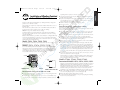
WTM210729 57962-24 rE.qx
6/11/01
1:43 PM
Page A
Installation Manual / User’s Manual
PROGRAM
Sprinkler Timers by Orbit®
CYCLE
START TIMES
Manuel d’installation / Manuel d’utilisation
M T W T F S S
INTERVAL
ODD
EVEN
1 2 3 4 5 6 7 8 9 10 11 12
ZONE
MANUAL
CLEAR
Manual de Instalación / Manual del usuario
Y H R
DA NT YEA
O
M
CYCLE
START
TIMES
DAY OF
WEEK
A
Programmateurs d’arrosage par Orbit®
2nd
1
2
3
4
B
ZONE
DURATION
ZONE
DURATION
CYCLE
START
TIMES
WATERING
INTERVAL
ENTER
NEXT
Programadores para sistemas de aspersión Orbit®
RAIN DELAY
RESET
TIME/DATE
OFF
AUTO
Manuale d’installazione / Manuale d’uso
Programmatore per irrigazione Orbit®
Installationshandbuch / Benutzerhandbuch
Orbit® Steuergerät für Bewässerungssysteme
MODELS
57674, 57676, 57679, 57672,
57694, 57696, 57699, 57692,
57662, 57664, 57666, 57669,
57682, 57684, 57686, 57689,
57962, 57964, 57966, 57969,
57972, 57974, 57976, 57979,
94102, 94104, 94106, 94109,
94112, 94114, 94116, 94119
WT 12/13
versions
1
2
3
4
5
6
7
8
9
10
11
12
PUMP
COM1
COM2
WTM210729 57962-24 rE.qx
6/11/01
1:43 PM
Page B
TABLE OF CONTENTS
ENGLISH
Introduction ...........................................................................1
Getting Started .......................................................................2
Programming..........................................................................3
Manual Operation ..................................................................4
Installation of Indoor Mount Timer........................................6
Installation of Outdoor Mount Timer .....................................7
Installing Valves, Pump Starts and Master Valves....................8
Other Quality Products and Accessories.....................................9
Trouble Shooting......................................................................10
ITALIANO
Introduzione ........................................................................33
Preparazione per l'uso ..........................................................34
Programmazione ..................................................................35
Funzionamento manuale......................................................37
Installazione del programmatore-montaggio interno ............38
Installazione del programmatore-montaggio esterno ............39
Installazione delle valvole, pompa d’avviamento
o valvola principale ..................................................................41
Altri prodotti ed accessori di qualità ........................................42
Individuazione ed eliminazione delle anomalie ........................43
FRANÇAIS
Introduction . . . . . . . . . . . . . . . . . . . . . . . . . . . . . . . . . . . . 11
Pour commencer . . . . . . . . . . . . . . . . . . . . . . . . . . . . . . . . . 12
Programmation . . . . . . . . . . . . . . . . . . . . . . . . . . . . . . . . . . 13
Manuel d’utilisation. . . . . . . . . . . . . . . . . . . . . . . . . . . . . . . 15
Installation du programmateur à montage intérieur . . . . . . . . . 17
Installation du programmateur à montage extérieur . . . . . . . . . 18
Installation des vannes, des relais de démarrage
de pompe et des vannes principales . . . . . . . . . . . . . . . . . . . . . . . 19
Autres produits et accessoires de qualité . . . . . . . . . . . . . . . . . . 20
Dépannage . . . . . . . . . . . . . . . . . . . . . . . . . . . . . . . . . . . . . . . 21
ESPAÑOL
Introducción ........................................................................22
Para comenzar......................................................................23
Programación .......................................................................24
Operación manual................................................................26
Instalación de un programador de montaje interior ............27
Instalación de un programador de montaje exterior .............28
Instalación de las válvulas, el encendido
de la bomba y las válvulas principales......................................30
Otros productos y accesorios de calidad ..................................31
Resolución de problemas..........................................................32
DEUTSCH
Einführung...........................................................................44
Anfang..................................................................................45
Programmierung ..................................................................46
Manueller und halbautomatischer Betriebsablauf .................47
Inneninstallation des Steuergerätes...................................... 49
Außeninstallation des Steuergerätes .................................... 50
Installation der Ventile, Pumpenanlasser und Hauptventile..51
Sonstige Qualitätsprodukte und Zubehör.................................52
Fehlerbehebung .......................................................................53
6/11/01
1
1:43 PM
Page 1
Introduction
section
1. Digital Display
A large LCD (Liquid Crystal Display) shows the time of day and indicates
many of the programming settings. The display is completely interactive
with all other controls.
2. Programming Keys
Thank you for selecting an Orbit® sprinkler Timer. Orbit® designers have
combined the simplicity of mechanical switches with the accuracy of digital
electronics to give you a Timer that is both easy to program and extremely
versatile. The Orbit® Timer provides convenience and flexibility, letting you
run a fully automatic, semi-automatic, or a manual watering program for all
your watering needs.
The Timer has seven push button keys for setup and program entry.
Working in conjunction with the rotary selector, the keys are used to set the
time of day, watering time, watering days, start times, and other functions.
3. Selector Dial
This large dial makes it easy to see which function is currently selected
and/or in which mode the Timer is set to operate.
Please read this manual completely before you begin to program and use the
controller. A few of the most notable design features include:
4. Reset Button
The reset button clears the time, date and user-defined programming but does not
remove the factory installed fail-safe program. To prevent an accidental reset, the
button is recessed into the panel and must be pressed with a small pointed object
such as a pen or pencil tip.
At-a-Glance Simplicity
By turning the rotary dial to one of nine settings you can review programming or easily make changes.
Arm Chair Programmable
Notable Programming Features
By inserting two AA alkaline batteries you can program the Timer prior to
installing it in its permanent location.
Two Watering Programs—Summary
The Timer gives you the option of using one or both of the independent programs. Note that each station can independently be set to either A or B or
both A and B programs.
Fail-Safe Program / Non-Volatile Program Memory
If the Timer loses AC power, the existing program will not be lost. After the
AC power returns, the Timer will recall the last program into memory and
there will be no need to re-program. If both the AC power is lost and the
batteries are dead or missing, the user will only need to reset the time and
date; all other program settings are held in non-volatile memory, and there is
no need for re-entry.
Program–A
This program lets you schedule selected stations to water on specific days of
the week or to water every 2nd day. Program A repeats itself continuously in
successive weeks.
Fuse
Program–B
Red flashing LED indicates blown fuse. The 0.75 amp slow-blow fuse provides circuit protection. For replacement, use WaterMaster 0.75 amp fuse or
equivalent.
Provides two options: One for odd or even day watering or for intervals ranging from everyday to every 28th day. This feature is designed to meet the
growing needs and restrictions imposed by local governments and to conserve water. The Timer automatically calculates odd and even days (by date)
for each month and makes adjustments for leap years to provide true odd
and even watering through the year 2095.
Lexan Language Covers
Available in English, French, Spanish, Italian, German.
PROGRAM
CYCLE
START TIMES
M T W T F S S
ZONE
MANUAL
A
Y H R
DA NT YEA
O
M
CYCLE
START
TIMES
DAY OF
WEEK
The Timer has the intelligence to “stack” start times that overlap.
If you enter two or more start times that overlap (in the same or in different
programs), the Timer will not activate two stations at the same time. Instead,
the Timer activates the first station and then activates the next station(s) in
sequence after the first station finishes its preset watering duration.
The Timer will NOT stack to the next calendar day. This prevents the Timer
from violating an odd or even day watering schedule.
1
INTERVAL
ODD
EVEN
1 2 3 4 5 6 7 8 9 10 11 12
CLEAR
Start-Time Stacking
2nd
1
2
3
4
2
B
ZONE
DURATION
ZONE
DURATION
CYCLE
START
TIMES
WATERING
INTERVAL
ENTER
NEXT
3
RAIN DELAY
RESET
TIME/DATE
OFF
Manual and Semi-Automatic Modes
4
AUTO
FIGURE 1: Location of Controls on the Timer
1
The Timer gives you a number of manual and semi-automatic modes for flexibility in
watering. You can override the Timer’s automatic programming in a variety of ways.
ENGLISH
WTM210729 57962-24 rE.qx
WTM210729 57962-24 rE.qx
2
6/11/01
1:43 PM
Page 2
PROGRAM
Getting Started
section
CYCLE
START TIMES
1
2
3
4
M T W T F S S
12:00
1 2 3 4 5 6 7 8 9 10 11 12
ZONE
Programming the Timer can be accomplished in just a few basic steps. Before
you begin programming, it is important to install the battery, set the time of
day and date, and establish a watering plan.
2nd
AM
INTERVAL
ODD
EVEN
▼ ▼▼
Y H R
DA NT YEA
O
M
FIGURE 3: LCD Display with Surrounding Information
Cursor
5:00
AM
▼▼▼
▼
▼▼▼▼
Remove the terminal cover.
Insert two AA batteries into the battery compartment.
Return the terminal cover to its closed position.
▼
The Timer requires two AA batteries to maintain the time and date in case of
AC power loss. In a typical installation, fully charged batteries should provide
sufficient power for approximately one year of operation.
▼
Install the Batteries
▼▼▼▼▼▼▼ ▼▼▼▼▼▼▼
FIGURE 4
Weak or missing batteries can cause the time and date to be erased after a
power failure. If this happens, you will need to install fully charged batteries
and re-enter the time and date. All other program settings will be maintained
in non-volatile memory. The display will show "LO BAT" when it is time to
replace the battery.
Caution: If a watering schedule is not entered into the Timer, the factory installed
fail-safe program will turn on each station every day for 10 minutes.
To avoid accidental valve activation, either turn the rotary dial to OFF or enter a
watering schedule.
Set the Time of Day and Date
To help you visualize how best to program the Timer, it might be helpful to
make a watering plan on paper. This will help you establish which days and
times you want to water.
Establish a Watering Schedule
If this is the first time the Timer has been programmed, you should press the
small recessed button labeled RESET. Pressing RESET does not affect the factory
installed fail-safe program [See Figure 2].
MANUAL
CLEAR
RAIN DELAY
ENTER
NEXT
RESET
FIGURE 2: Programming Keys
Turn the rotary dial to the TIME/DATE position [See Figure 3].
12:00 AM will appear in the display with three arrows pointing to the year,
month, and day.
Use the + and - keys to set the correct time of day. When the correct time
of day is reached, press the ENTER key to lock in the time. To increase or
decrease more rapidly, hold down either the + or – keys until the display
goes into rapid advance mode.
A blinking cursor will appear below the arrow for the year, month, and
date when programming [See Figure 4].
Use the + and – keys to set the correct year, then press ENTER.
Use the + and – keys to set the correct month, then press ENTER.
Use the + and – keys to set the correct date, then press ENTER.
2
6/11/01
3
1:43 PM
Page 3
The display will show which program you have selected with an "A" or "B"
and the - - cursor blinking at station "1" [See Figure 6].
Programming
section
PROGRAM
CYCLE
START TIMES
The Timer has two programs you can setup to control a variety of watering
schedules. Depending on your needs, you can use either or both programs.
1
2
3
4
PROGRAM
CYCLE
START TIMES
1 2 3 4 5 6 7 8 9 10 11 12
ZONE
M T W T F S S
2nd
A
DAY OF
WEEK
ZONE
DURATION
A
INTERVAL
ODD
EVEN
CYCLE
START
TIMES
ZONE
Y H R
DA NT YEA
O
M
FIGURE 7: LCD Display with Watering Days
Press ENTER to activate watering on Monday. An arrow appears under M
and the cursor will advance to Tuesday (“T”), press ENTER to activate watering on this day. Repeat these steps for all days of the week.
To skip a day, press NEXT.
To delete a previously entered day, press CLEAR
If you want to water every second day, press the NEXT key to advance the
cursor to “2nd”, then press ENTER.
DAY OF
WEEK
ZONE
DURATION
--.--
1
2
3
4
1 2 3 4 5 6 7 8 9 10 11 12
Up to four start times can be entered per program (A or B).
CYCLE
START TIMES
CYCLE
START
TIMES
Y H R
DA NT YEA
O
M
Turn the rotary dial to DAY OF WEEK in program A. The display will show an
“A” and the cursor will blink under the days of week M, T, W, T, F, S, S
(Monday, Tuesday, etc.) [See Figure 7].
Set the time you want to begin watering for start time 1 using the
+ or – keys, then press the ENTER key. The display will advance to START 2.
For additional start times, simply repeat this procedure by using the + and
– keys to enter the time and then press ENTER. Remember, Each start time
will activate all stations that are set to water in the specified program. There are
not separate start times for each station. Start times do not correspond to specific stations.
A
INTERVAL
ODD
EVEN
Assigning Watering Days for Program A
The way you set the cycle start time is the same for both programs. Turn
the rotary dial to the CYCLE START TIMES position in the program that you
want to set. The display will show an A or B depending on which program
you have selected. The display will show —— : ——
and a blinking cursor in CYCLE START 1 location [See Figure 5].
2nd
DAY OF
WEEK
FIGURE 6: Station Duration for Program A
Note: A start time is the time of day that the program begins watering the first station,
and all other stations in the program will then follow in sequence. There are not separate start times for each station. Start times do not correspond to specific stations, but to
programs (A or B). If you enter more than one start time, all stations in the specified
program will water again (in sequence).
M T W T F S S
A
You can set the watering duration from 1 to 99 minutes. Press and hold
the + key to advance the number of minutes, or use the - key to go in
reverse, then press ENTER. When the minutes are set, “A” or “B” will
appear over station 1 and the cursor will advance to station 2 and begin
blinking.
Simply repeat these steps to set watering durations for all zones on this
program
To skip a station, press the NEXT key.
To erase previously programmed watering durations, press the CLEAR key.
Start Times for Program A or B
A
--.-ZONE
You have the option of entering your watering schedule in whatever order
you like. This feature makes it very easy to review and change your watering
schedule. Your settings can be changed at any time—while you’re setting up
the initial schedule or even after years of operation.
PROGRAM
2nd
ZONE
DURATION
1 2 3 4 5 6 7 8 9 10 11 12
Enter the Watering Schedule in Any Order
1
2
3
4
M T W T F S S
A
INTERVAL
ODD
EVEN
CYCLE
START
TIMES
Note: If you choose to water every 2nd day, you cannot set specific days of the
week for watering
Y H R
DA NT YEA
O
M
FIGURE 5: LCD Display with Start Time
Assigning Watering Intervals for Program B
Water Duration for Program A or B
Note: Both programs require watering durations to be programmed.
Program B is used to water at specific intervals between days (1 to 28), or on
odd or even calender dates. The Timer has a leap-year compensator and will
ensure conformance to the odd and even schedule through the year 2095.
Turn the rotary dial to ZONE DURATION position in either the A or B program.
Turn the rotary dial to WATERING INTERVAL. The cursor will blink to the left
of the word INTERVAL [See Figure 8].
3
ENGLISH
WTM210729 57962-24 rE.qx
WTM210729 57962-24 rE.qx
6/11/01
1:43 PM
Page 4
4
Semi-Automatic &
Manual Operation
section
PROGRAM
CYCLE
START TIMES
1
2
3
4
M T W T F S S
CYCLE
START
TIMES
2nd
B
ZONE
DURATION
B
-1 2 3 4 5 6 7 8 9 10 11 12
ZONE
DAYS
INTERVAL
ODD
EVEN
The Orbit Timer has the ability to override the automatic program without
disturbing the preset program.
WATERING
INTERVAL
Y H R
DA NT YEA
O
M
Using the Semi-Automatic Mode
FIGURE 8: LCD Display with Watering Interval
(All stations cycle once both A & B programs)
Press and hold the + or - keys to select the number of days between watering. Example: If you want to water once every 10 days, set the interval at 10.
To activate the watering interval, press ENTER.
Turn the rotary dial to AUTO, then press the MANUAL key. The display will
show “AB”, “MANUAL”, and “ALL” will be blinking [See Figure 10].
This indicates all stations will semi-automatically water for their assigned
durations in sequence.
Note: If an interval of “3” is entered today, the Timer will water for the first time
today, and then again every “3” days.
To activate the assigned water durations in the A and B programs for each
station, press ENTER.
To select odd or even day watering, press NEXT. The cursor will move to
either the odd or even setting, then press ENTER.
To erase a schedule, press CLEAR. To enter a new schedule, press NEXT.
PROGRAM
CYCLE
START TIMES
Reviewing and Changing Your Program
M T W T F S S
MANUAL
A
The Orbit Timer lets you easily review a complete watering plan.
ALL
1 2 3 4 5 6 7 8 9 10 11 12
ZONE
For example, to review Program-A watering start times, simply turn the
rotary dial to the CYCLE START TIMES position in Program-A and check the times
that have been entered. Using the NEXT key, you can advance through the
schedule without fear of disturbing any programming. If you want to change
the start times, watering days, or interval, simply follow the directions for
that program. After reviewing or changing a watering schedule, remember to
turn the rotary dial back to AUTO.
2nd
A B
1
2
3
4
INTERVAL
ODD
EVEN
Y H R
DA NT YEA
O
M
FIGURE 10: Semi-Automatic Watering for Stations Assigned to A and B Programs
Note: Water durations assigned to station 1 in program A will water first, then
move to station 1 in program B before advancing to the second station and will continue alternating. Only those stations assigned a watering duration will water when
using the manual or semi-automatic mode [See Figure 11].
PROGRAM
Ready for Automatic Operation
CYCLE
START TIMES
After programming is complete, turn the rotary dial to AUTO [See Figure 9].
The Timer is now fully programmed and ready to use in the automatic mode.
In automatic mode, each program will operate sequentially, starting with
Program-A.
M T W T F S S
A B
1
2
3
4
A
1 2 3 4 5 6 7 8 9 10 11 12
ZONE
PROGRAM
CYCLE
START TIMES
1
2
3
4
PM
INTERVAL
ODD
EVEN
Y H R
DA NT YEA
O
M
M T W T F S S
2nd
A B
ON
MANUAL
A
1 2 3 4 5 6 7 8 9 10 11 12
ZONE
TIME/DATE
2nd
8:00
MANUAL
10
INTERVAL
ODD
EVEN
MINS
Y H R
DA NT YEA
O
M
OFF
FIGURE 11: Semi-Automatic Watering Entered for A and B Programs, All Stations
AUTO
FIGURE 9: Ready for Automatic Operation
(All stations cycle once, A program only)
To activate each stations assigned watering durations for the A program
only, press the MANUAL key, followed by the NEXT key. This will activate stations with assigned watering durations in the A program only. To initiate this
4
6/11/01
1:43 PM
Page 5
semi-automatic watering, press ENTER [See Figure 12].
(All stations cycle once, B program only)
PROGRAM
CYCLE
START TIMES
To activate each stations assigned watering durations for the B program
only, press the MANUAL key, followed by pressing the NEXT key two distinct
times. This will activate only those stations with assigned watering durations
in the B program only. To initiate this semi-automatic watering, press ENTER.
1
2
3
4
M T W T F S S
A
1 2 3 4 5 6 7 8 9 10 11 12
ZONE
PROGRAM
PROGRAM
CYCLE
START TIMES
M T W T F S S
A
1
2
3
4
MANUAL
A
8:00
1 2 3 4 5 6 7 8 9 10 11 12
ZONE
PROGRAM
CYCLE
START TIMES
2nd
PM
CYCLE
START TIMES
INTERVAL
ODD
EVEN
ON
1 2 3 4 5 6 7 8 9 10 11 12
ZONE
MINS
INTERVAL
ODD
EVEN
Using the User Selectable Rain Delay Mode
To stop automatic watering for 24, 48, or 72 hours, use the RAIN DELAY mode key.
With the rotary dial set to AUTO, press the RAIN DELAY key once then press
ENTER. The Timer will force a 24-hour interruption of all scheduled watering. After 24 hours, the Timer will automatically return to its initial
watering schedule.
The manual operation mode allows you to set durations in any of the stations
from 1 to 99 minutes.
Turn the rotary dial to AUTO.
To increase the rain delay to 48 or 72 hours simply press the RAIN DELAY key
again until the desired delay time is displayed, then press ENTER.
Press the MANUAL key. Then press NEXT three times. The display will show
a blinking cursor on station 1 along with - - MINS [See Figure 13].
CYCLE
START TIMES
MANUAL
1 2 3 4 5 6 7 8 9 10 11 12
ZONE
To cancel the rain delay mode, press CLEAR [See Figure 15].
2nd
--
Y H R
DA NT YEA
O
M
To halt or discontinue semi-automatic or manual watering, press the CLEAR
key once. The Timer will revert to your original automatic watering plan.
Y H R
DA NT YEA
O
M
M T W T F S S
INTERVAL
ODD
EVEN
FIGURE 14: Manual Watering Station 3 for Five Minutes
Using Manual Operation
PROGRAM
MINS
Note: After the MANUAL key has been pushed, if a selection is not made within 60
seconds the display returns to the time of day.
FIGURE 12: Manual Watering in Either the A or B Program Only
1
2
3
4
2nd
5
MANUAL
ZONE
2nd
10
MANUAL
A
M T W T F S S
1 2 3 4 5 6 7 8 9 10 11 12
A
1
2
3
4
ON
INTERVAL
ODD
EVEN
PM
Y H R
DA NT YEA
O
M
A
Y H R
DA NT YEA
O
M
M T W T F S S
1
2
3
4
2nd
8:00
MANUAL
Note: While in rain delay mode, the timer will display the remaining hours
(counting down) to the end of the accepted delay alternating with the current
time and date. No other key besides CLEAR is accepted while the Timer is in the
rain delay mode.
INTERVAL
ODD
EVEN
MINS
Y H R
DA NT YEA
O
M
FIGURE 13
PROGRAM
To set the number of minutes for watering duration, press and hold the +
key to advance to desired number of watering minutes. Use the - key to
go in reverse. Press ENTER to begin watering.
CYCLE
START TIMES
To skip a station, press NEXT until the cursor is blinking over the station
number you wish to program. Example: To set station 3 for five minutes,
press the MANUAL key; then press the NEXT key five times to select the manual operation mode and advance to watering for station 3; using the + or key, set the manual watering duration to five minutes; then press ENTER
[See Figure 14].
1
2
3
4
OFF
M T W T F S S
2nd
PM
DELAY
1 2 3 4 5 6 7 8 9 10 11 12
ZONE
INTERVAL
ODD
EVEN
Y H R
DA NT YEA
O
M
FIGURE 15: Display Showing Rain Delay
Complete System Shut Down
To shut the system down, turn the rotary dial to the OFF position. The Timer
remains programmed but will not water.
5
ENGLISH
WTM210729 57962-24 rE.qx
WTM210729 57962-24 rE.qx
5
section
6/11/01
1:43 PM
Page 6
3. Connecting the Transformer
Installation of Indoor
Mount Timer
With the wiring terminal shroud off, find the two terminal holes labeled
“24 VAC.” Make sure the transformer is not plugged in. Insert one of the
two power leads from the transformer into each terminal. It doesn’t matter
which lead goes into which terminal.
It may be necessary to open the terminal to allow for wire insertion or
removal. To do this, simply press upward on the tab located on top of the
terminal [See Figure 17].
Plug in the transformer
Warning: Do not link two or more controllers together with one transformer.
Slide the shroud back on.
Install the controller in 4 easy steps—
1. Choosing a Timer Location
2. Mounting the Timer
3. Connecting the Transformer
4. Connecting Valve Wires to Timer
1. Choosing a Timer Location
1
2
3
4
5
6
7
8
9
10
11
12 PUMP COM1 COM2 24V 24V
Select a location near a standard electrical outlet. Avoid using an outlet
controlled by an ON/OFF switch.
The timer should not be exposed to the weather or operate at temperatures
below 14 degrees or above 113 degrees Fahrenheit (-10 to 45 degrees
Celsius). Avoid direct sunlight. For use under “normal pollution conditions”.
Installation works best in a garage or protected area. The timer should not
be mounted outdoors.
2. Mounting the Timer
A mounting template is provided to assist you in mounting the timer.
Screw a No. 8 screw at eye level leaving the screw head extended out from
the wall about 1/8 inch. Use expanding anchors in plaster or masonry if
necessary.
Slip the keyhole slot in the back
of the timer over the extended screw.
Screw a No. 8 screw through
each of the two holes at the bottom of the box into the wall
[See Figure 16].
Keyhole
FIGURE 17: Connecting Transformer
Precautions:
• This controller is not intended for use by young children or infirm persons without
supervision.
• Young children should be supervised to ensure they do not play with the controller.
No. 8 Screw
Wall
Screw holes
FIGURE 16: Mounting of an Indoor Timer
6
6
section
6/11/01
1:43 PM
Page 7
Installation of Weather-Resistant
Indoor-Outdoor Controllers
All our Weather-resistant Indoor/Outdoor controllers can run at temperatures
between 35 and 140 degrees Fahrenheit (0 to 60degrees Celsius). Storage temperature is -4 to 149F (-20 to 65C).
Direct sunlight can easily increase temperatures inside the Controllers so chose a
shaded location.
The controllers are weather-resistant to UL-50 and ETL® Listed, but should not
be placed in areas where continuous water could cause damage.
Caution: Do not open the Controller when it is raining.
To make installation easier the Controller has a removable door. Remember to
leave at least 7ins (18cm) to the left of the controller box for the door to swing
open after installation.
Check the model number of your timer: various models are configured differently
to meet national requirements, look for the section covering the model number
on your controller. The model number can be found on the back of the housing,
together with other useful information.
Models 57694, 57696, 57699, 57692
are for installation in Australia, New Zealand, and South Africa using the fitted line cord.
Models 57974, 57976, 57979, 57972
are for 110/117VAC operation and are suitable for either wall-hanging installation
using the line cord fitted or permanent installation. You need to decide which type
of installation you are going to use. Ensure that you have the appropriate electrical
power available at the location you intend to use. If used outdoors with the line
cord, a suitable weatherproof power outlet must be available.
PROGRAM
Door
Hinge
Door
Hinge
CYCLE
START TIMES
M T W T F S S
2nd
1
2
3
4
INTERVAL
ODD
EVEN
1 2 3 4 5 6 7 8 9 10 11 12
ZONE
MANUAL
Y H
DA NT YEAR
MO
CYCLE
START
TIMES
DAY OF
WEEK
A
B
ZONE
DURATION
ZONE
DURATION
CLEAR
CYCLE
START
TIMES
WATERING
INTERVAL
RESET
TIME/DATE
OFF
AUTO
2
3
4
Installation using permanent wiring
Preparing the Controller for Permanent Installation
Before commencing to install the controller you must remove the fitted line cord
and replace with the pigtail wires provided.
Take off the terminal compartment cover by unscrewing the two screws and
pulling the plastic cover forward. [See figure 18], this reveals the AC Power
Cover [Figure 21].
Remove the rubber weather plug from the hole in the center and unscrew the
one fixing screw, pull the plastic cover forward to reveal the AC wiring.
Use a punch to create a hole in the blind Bottom Mounting Hole on the back
of the controller box [Figure 19: Bottom Mounting Hole].
Loosen the screw on the cord restraint and the three screws on the terminal
block and remove the line cord completely.
Feed the three wires of the pigtail through the exit nipple, under the strain
relief, and cross to the terminal block. Fasten the wires to the terminal block
ensuring that the black wire is connected to the Live terminal marked L, the
white wire is connected to the Neutral terminal marked N, and the green wire
is connected to the Earth terminal marked E. Ensure that the terminal screws
and the strain relief screw are all firmly tightened. Check that the wires are
clear of any obstruction and will not be trapped by the AC Power Cover when
it is replaced.
Replace the AC Power Cover and screw tight, do not force into place, if resistance is met check that no wires are trapped.
The Controller is now ready for permanent installation; follow all the instructions for the following models to complete the installation. (use expanding
anchors in plaster or masonry if necessary).
ENTER
NEXT
RAIN DELAY
1
expanding anchors in plaster or masonry if necessary).
Using the lower mark on the template, affix a No. 8 screw (included), again
leaving the head protruding.
Slip the slotted keyhole in the back of the Controller over the extended upper
screw and allow the lower screw to recess into the lower hole in order to prevent the Controller from swinging. [See Fig.19].
The line cord may now be inserted into the power outlet.
Proceed to section 7.
5
6
7
8
9
10
11
12
PUMP
COM1
Slotted
Slotted
Hole
Hole
COM2
Terminal
Terminal
Compartment
Compartment
Cover
Cover
Terminal Cover
Screws
Terminal
Cover
Screws
FIGURE 18: Outdoor Timer, Showing Terminal Cover
Bottom
Bottom
Mounting
Mounting
Hole
Hole
FIGURE 19: Back of Timer Box
Installation using the fitted line cord
Use the mounting template provided to assist you in preparing the mounting location: choose a flat, clean surface.
Using the upper mark on the template, insert a No. 8 screw (included) at eye
7
level leaving the screw head about 1/8th inch (3mm) out from the wall. (Use
Models 57684, 57686, 57689, 57682
International Models 94114, 94116, 94119, 94112
All the above listed models are designed for permanent installation only. Local
building and electrical codes usually require that an approved electrical conduit and electrical fittings be used to connect exterior wall-mounted
equipment to AC power. Please check local codes. Any permanent connection
should be made by a licensed electrical contractor in accordance with the
requirements of the National Electrical Code and other state and local codes.
Take off the terminal compartment cover of the controller by unscrewing the
two screws and pulling the plastic cover forward. [Figure 18].
Remove the rubber weather plug from the screw hole.
Use the mounting template provided to assist you in preparing the mounting
location: choose a flat, clean surface.
ENGLISH
WTM210729 57962-24 rE.qx
WTM210729 57962-24 rE.qx
6/11/01
1:43 PM
Page 8
Using the upper mark on the template, insert a No. 8 screw (included) at eye
level leaving the screw head about 1/8th inch (3mm) out from the wall. (Use
expanding anchors in plaster or masonry if necessary).
Slip the slotted keyhole in the back of the controller box over the extended
screw [Figure 19].
Push a No. 8 screw (included) through the Bottom Mounting Hole [Figure 19]
in the controller box and tighten until the box is held firmly to the wall, but
do not over-tighten.
The Controller has separate compartments for the AC line power input and the
low voltage outputs. You must keep the input power and the low voltage in their
separate places when wiring the
controller box.
The controller has a built in transformer that must be connected to
an AC line voltage source. Check
the back of the controller box for
power requirements. This connec1/2" (13mm) NPT Nipple
Junction Box
tion should be made by a licensed
electrical contractor in accordance
Wire Connectors
with the requirements of the
National Electrical Code and other
state and local codes.
'AA' SIZE BATTERY
1
2
3
4
5
6
7
OPEN
'AA' SIZE BATTERY
8
9
10
11
12
PUMP COM1 COM2
7
section
Installing Valves, Pump Start
Relays & Master Valves
1. Wiring the Electric Valves
If the distance between the controller and valves is under 700 feet (210
m), use WaterMaster® sprinkler wire or 20 gauge (AWG) plastic jacketed
thermostat wire to connect the controller to the valves. If the distance is
over 700 feet (210 m), use 16 gauge (AWG) wire. Terminals accept up to
14 gauge wire. The wire can be buried in the ground; however, for more
protection wires can be pulled through conduit and buried underground.
Be careful to avoid burying the wires in locations where they could be
damaged by digging or trenching in the future.
1/2" (13 mm)
NPT Nipple
Jacket
Junction
Box
Specific
Zone Wire
Wire
Connectors
Wire
Connectors
in Grease Caps
FIGURE 21: AC Wiring Using Junction Box
Wiring the AC input
Caution: do not connect the controller to one phase of a there-phase power system
used by a pump or other electrical equipment.
The controller has a nipple-mounted external power connection [Figure 21]. Use
this 1/2 inch (13mm) NPT nipple to connect the controller to a standard electrical junction box that should be UL Listed (or equivalent) or comply with IEC or
EN standards (or equivalent).
Turn off the AC power at the AC circuit breaker and apply an appropriate
safety lockout. Verify that the power has been turned off to the installation site
using an AC voltmeter set for the correct measurement range.
Use power feed wire of 14 gauge (AWG) minimum with a temperature rating
of 155 degrees Fahrenheit (68 degrees Celsius) or higher.
Install the conduit and associated fittings. Connect the AC electrical power
wiring to the source by following all the right codes and local standards.
Connect the junction box (not included) to the NPT nipple [Figure 21].
Connect the source power conduit to the entrance of the junction box, following all the appropriate codes.
Connect the source wires to the wires extending from the controller. Take
care to follow the correct color code. For USA: connect the Green for
Ground, Black for Live, and White for Neutral. Often the source ground may
be bare copper conductor rather than green wire. For Europe: Live is Brown
and Neutral is Blue, there is no ground connection required. Be sure that all
wires are connected to the proper source wire.
Make sure all connections are made with code-approved insulated connectors.
Be sure to place a weatherproof gasket and lid on the junction box.
8
Common
Wires
Solenoids
Valves
FIGURE 22: Connecting Timer Wires to Valves
Each valve has two wires. One wire is to be connected as the common.
The common wires for all the valves can be connected together to one
common wire going to the timer. The other valve wire is to be connected
to the specific station wire that will control that valve
[See Figure 22].
All wires should be joined together using wire nuts, solder, and/or vinyl
tape. For additional protection to waterproof connections, a WaterMaster®
grease cap can be used.
To avoid electrical hazards, only one valve should be connected to
each station.
2. Connecting Valve Wires to the Timer
Remove the terminal compartment cover.
Strip 1/4" (6 mm) of the plastic insulation off the end of each wire.
Determine which valve you want to connect to which station. Connect
6/11/01
1:43 PM
Page 9
OTHER QUALITY PRODUCTS AND ACCESSORIES
each valve wire to its station terminal (labeled 1-12) by inserting the bare
wire fully into the terminal.
It may be necessary to open the terminal to allow for wire insertion or
removal. To do this, simply press upward on the tab located on top of the
terminal [See Figure 23].
Connect the common wire to the terminal labeled COM [See Figure 23].
1
2
3
4
5
6
7
8
9
10
11
ENGLISH
WTM210729 57962-24 rE.qx
Automatic Rain Shut-Off
For automatic rain shut-off, contact your Orbit®
dealer to purchase an Orbit® Model 57091
(94060) automatic rain shut-off switch. The
rain shut-off easily connects to the timer and
prevents overwatering during rainy periods.
12 PUMP COM1 COM2 24V 24V
Weather Resistant Timer Box
Allows outdoor installation of most brands of
indoor mount timers.
UL® listed.
®
8-Zone
UL
WaterMaster
CLASS 2 TRANSFORMER
INPUT 120V AC 60Hz 35W
OUTPUT 24V AC 1.2 AMP
MODEL NO. DV. 24124
CAUTION: INDOOR USE ONLY
®
To Station Valve
WaterMaster
Automatic Valves
Durable, non-corrosive plastic construction.
Automatic valves are available in anti-siphon
or straight valves with safe, low voltage.
Automatic Converters
Durable non-corrosive plastic construction.
Converts most brands of plastic or brass
valves to automatic.
FIGURE 23: Connecting Valve Wires
Grease Caps
Note: Only one wire can be installed into each terminal. If more than two common
wires are used in your system, splice several together so only one wire runs into
each of the COM terminals. Protect the splice connection with a wire nut.
Protects low voltage wires from corrosion
or shorts.
Remote Control Transmitter and Receiver
Australian Rating Information
Control your sprinklers with the touch of
a button up to 200' (60 m) from your
sprinkler controller.
Transformer:
Output:
Input:
600 mA
240 VAC
24 VAC
50 Hz
50 Hz
Remote
Control
Timer Link ™
Remote
Control
Timer Link ™
6 STATION TRANSMITTER
1
4
Controller Ouput:
ON
6 STATION RECEIVER
24 VAC
MODEL #57013
5
Stations
ON
10 min
9
2
MODEL #57036
3
6
ALL OFF
2 min
ON
30 min
ON
60 min
WTM210729 57962-24 rE.qx
6/11/01
1:43 PM
Page 10
Help
TROUBLESHOOTING
Before returning this timer to the store, contact
Orbit® Technical Service at: 1-800-488-6156.
Possible Causes of Problems
One or more stations do not turn on:
Listings
1. Faulty solenoid.
2. Wire broken or not connected.
3. Flow control stem screwed down, shutting valve off.
4. Programming is incorrect.
The timer is tested to UL-1951 (Indoor models) and UL-50
(outdoor models) standard and is ETL® listed. Appropriate international models are CSA® and CE® approved.
Stations turn on when they are not supposed to:
Trademark Notice
1. Water pressure is too high.
2. More than one start time is programmed.
WaterMaster ® is registered trademark of Orbit® Irrigation
Products, Inc.
One station is stuck on and will not shut off:
All stations do not turn on:
The information in this manual is primarily intended for the user
who will establish a watering schedule and enter that schedule into
the timer. This product is intended to be used as an automatic timer
for activating 24 VAC irrigation valves, as described in this manual.
1. Transformer defective or not connected.
2. Programming is incorrect.
3. Fuse has been blown.
WaterMaster® by Orbit® Limited Four Year Warranty
1. Faulty valve.
2. Particles of dirt or debris stuck in valve.
3. Valve diaphragm faulty.
Orbit® Irrigation Products, Inc. warrants to its customers that its
WaterMaster® products will be free from defects in materials and
workmanship for a period of four years from the date of purchase. We will replace, free of charge, the defective part or parts
found to be defective under normal use and service for a period
of up to four years after purchase (proof of purchase required).
We reserve the right to inspect the defective part prior to
replacement. Orbit® Irrigation Products, Inc. will not be responsible for consequential or incidental cost or damage caused by
the product failure. Orbit® liability under this warranty is limited
solely to the replacement or repair of defective parts.
Controller will not power up:
1. Fuse has been blown.
2. Transformer not plugged into an operational AC outlet.
Stations continue to turn on and off when they are not programmed to:
1. More than one start time is programmed with overlapping schedules.
2. Excessive pressure.
Fuse blows repeatedly:
1. Short in wiring or solenoids.
To exercise your warranty, return the unit to your dealer with a
copy of the sales receipt.
10