1
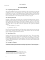
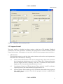
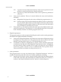
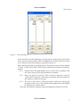
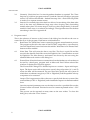
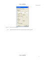
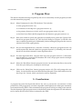
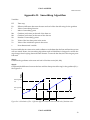
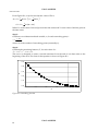
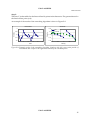
UNCLASSIFIED A User Manual for a Program to Convert CFD Ship Wake Data to a Format Suitable for the FlightLab Robert Toffoletto Air Operations Division Defence Science and Technology Organisation DSTO-GD-0633 ABSTRACT This report provides details of the program, WakeData, including a basic user manual and some of the theory used to develop the program. WakeData was developed to convert the vast amounts of data generated by Computational Fluid Dynamics codes into a form that is compatible with FlightLab, the helicopter simulation environment used by DSTO. The development of this program is seen as the first step in the development of a risk reduction tool for future First of Class Flight Trials that will be conducted by the ADF. RELEASE LIMITATION Approved for public release UNCLASSIFIED UNCLASSIFIED Published by Air Operations Division DSTO Defence Science and Technology Organisation 506 Lorimer St Fishermans Bend, Victoria 3207 Australia Telephone: (03) 9626 7000 Fax: (03) 9626 7999 © Commonwealth of Australia 2011 AR-014-964 April 2011 APPROVED FOR PUBLIC RELEASE UNCLASSIFIED UNCLASSIFIED A User Manual for a Program to Convert CFD Ship Wake Data to a Format Suitable for the FlightLab Executive Summary One of the main reasons why the operation of helicopters from naval frigates is so hazardous is the interaction between the rotor system and the turbulent airwake behind the ship. This is especially true during launch and recovery, when aerodynamic loading of the rotor system can be considerably altered by the passage through an eddy or a region of cross-flow. The changes in rotor loading might affect the aircraft control and the power margin for a safe landing. In the light of this problem, the Defence Science and Technology Organisation (DSTO) has a growing research interest in the interaction between a bluff body airwake and rotary wing aircraft. A clear understanding of this flow field and the behaviour of the helicopter when immersed in such environments will help DSTO to establish the margin of safety for helicopter shipborne operations. In recent years DSTO has developed some expertise in the development of Computational Fluid Dynamics (CFD) models of ships for the purposes of studying the airwake in the vicinity of the heli-deck. DSTO has used this expertise to evaluate the airwake around the Landing Helicopter Dock (LHD) ship. The LHD, or Canberra class ship is a large flat deck ship with as many as 6 helicopter landing spots. DSTO has also investigated the effect of the Anti-Ship Missile Defence (ASMD) modifications to the ANZAC frigate on helicopter operations using CFD. DSTO has now commenced a new task where it will attempt to combine the well developed flight models within DSTO and the ship-airwake databases produced using CFD to predict the potentially high risk conditions during launch and recovery operations from ships. In effect the helicopter flight model will be immersed in the ship airwake at varying wind over deck angles and speeds to investigate what affect this has on the helicopters' control and power margins. The outcome of this task will be a tool that can be used by the ADF when planning First of Class Flight Trials (FOCFT). As a first step, DSTO needed to develop a method of converting the vast amounts of data generated by the CFD codes into a form that is compatible with FlightLab, the simulation environment used by DSTO when developing helicopter flight models. As a result, the program ‘WakeData’ was developed. This report provides details of the computer program, WakeData, including a basic user manual and some of the theory used to develop the program. UNCLASSIFIED UNCLASSIFIED Contents NOMENCLATURE 1. INTRODUCTION .....................................................................................................................1 2. SUMMARY OF FLIGHTLAB .................................................................................................2 2.1 General ..............................................................................................................................2 2.2 Ship Airwake Module ...................................................................................................2 3. USER MANUAL ........................................................................................................................4 3.1 Computing Requirements.............................................................................................4 3.2 Data Requirements .........................................................................................................4 3.3 Initialisation Files ...........................................................................................................4 3.4 Starting the Program ......................................................................................................4 3.5 Program Control ..............................................................................................................5 4. PROGRAM FLOW ..................................................................................................................10 5. CONCLUSIONS ......................................................................................................................10 APPENDIX A: SCOPE SAV FORMAT............................................................................ 11 A.1. Example Grid File .......................................................................... 12 A.2. Example Data File .......................................................................... 12 APPENDIX B: SMOOTHING ALGORITHM ............................................................... 13 UNCLASSIFIED UNCLASSIFIED Nomenclature All acronyms used in this document are defined at first use. However, to aid the reader a list of the most common acronyms used in this document follows. Acronyms ART Advanced Rotorcraft Technologies Pty Ltd ASMD Anti-Ship Missile Defence CFD Computational Fluid Dynamics DSTO Defence Science and Technology Organisation HiL Human in the Loop LHD Landing Helicopter Docks SFS Simple Frigate Shape SHOL Ship Helicopter Operating Limit TTCP The Technical Cooperation Program WOD Wind Over Deck UNCLASSIFIED UNCLASSIFIED DSTO-GD-0633 1. Introduction One of the main reasons why the operation of helicopters from naval frigates is so hazardous is the interaction between the rotor system and the turbulent airwake behind the ship. This is especially true during launch and recovery, when aerodynamic loading of the rotor system can be considerably altered by the passage through an eddy or a region of cross-flow. The changes in rotor loading might affect the aircraft control and the power margin for a safe landing. In the light of this problem, the Defence Science and Technology Organisation (DSTO), together with a number of other partners within The Technical Cooperation Program (TTCP), have a growing research interest in the interaction between a bluff body airwake and rotary wing aircraft. A clear understanding of this flow field and the behaviour of the helicopter when immersed in such environments will help DSTO to establish the margin of safety for helicopter ship borne operations. In 1996, researchers from the US, UK, Australia, and Canada, through the auspices of TTCP, agreed on a simplified standard ship model. The Simplified Frigate Shape (SFS) has a block superstructure consisting of a forward funnel followed by a backwards facing step to an aft flight deck, and a second backwards facing step at the stern. The flight deck region has dimensions similar to those of the ANZAC and FFG-7 class frigates in use by the Royal Australian Navy. The aim at DSTO was to gain an understanding of the typical flow field structures around the flight deck and how they affect the performance and handling characteristics of rotorcraft. Since the initial SFS research program, DSTO has used that experience to develop unsteady airwake databases to be used in the DSTO Human in the Loop (HIL) simulations involving helicopter-ship landings. DSTO has also used this expertise to evaluate the airwake around the Landing Helicopter Dock (LHD) ship. The LHD, or Canberra class ship is a large flat deck ship with as many as 6 helicopter landing spots. DSTO has also investigated the effect of the AntiShip Missile Defence (ASMD) modifications to the ANZAC frigate on helicopter operations. In recent years, several countries (including the US and UK) have attempted to develop virtual Ship Helicopter Operating Limits (SHOLs) using a combination of developed airwake databases, often obtained using Computational Fluid Dynamics (CFD) codes; high-fidelity helicopter dynamic models; and high-fidelity simulation centres. However, DSTO believes such technologies have not sufficiently advanced to be employed for SHOL development with the required confidence. As an alternative, DSTO will attempt to use these same tools without a pilot-in-the-loop simulator to predict the potentially high risk conditions during launch and recovery operations from ships. In effect the helicopter flight model will be immersed in the ship airwake at varying wind over deck angles and speeds to investigate what affect this has on the helicopters' control and power margins. As a first step, DSTO needed to develop a method of converting the vast amounts of data generated by the CFD codes into a form that is compatible with FlightLab 1 , the simulation environment used by DSTO when developing helicopter flight models. As a result, the program ‘WakeData’ was developed. 1 Developed by Advanced Rotorcraft Technology, Inc (ART), Sunnyvale, California, USA UNCLASSIFIED 1 UNCLASSIFIED DSTO-GD-0633 This report provides details of the computer program, WakeData, including a basic user manual and some of the theory used to develop the program. 2. Summary of FlightLab 2.1 General FlightLab is the current helicopter modelling environment used by DSTO. It is a commercial tool developed by Advanced Rotorcraft Technology Inc. (ART), for rotorcraft modelling and analysis. FlightLab is based on the Scope environment. This is an interpretive language that uses MATLAB 2 -like syntax together with new language constructs for building and solving nonlinear dynamic models. FlightLab provides a large range of aerospace and dynamics related components, which are used to develop flight models using object oriented design. FlightLab uses multi-body dynamics to simulate real-time models. Generic modelling components are assigned specific values and parameters defining the aircraft. Each component is a self-contained dynamic entity that is interconnected to all other components through a child and parent structure. Solution components then take care of the kinematic and force interactions throughout the model. 2.2 Ship Airwake Module As part of the multi-body system, FlightLab allows the helicopter model to interact with several external objects such as slung loads, external stores, ship motion, ship airwake and ground effect. For this task the module relating to the helicopter’s interaction with the ship airwake is of interest. For the ship airwake interaction, FlightLab models the airwake interference on the helicopter and its sub-systems. The user has the option of selecting several elements to be effected, including main and tail rotors, aerodynamic surfaces, fuselage and wing. For the rotors, the user also has the choice of allowing interference on: all aerodynamic collocation points, one reference point (hub), or a weighted reference point. FlightLab also allows the user to employ one of several modelling techniques, including: table look-up; map look-up, which allows one of the grid dimensions to be non-rectangular; and ship deck models, which provides full and partial ground effect due to the ship deck. The table lookup was the method chosen for this task. The tables used by FlightLab are in the program’s unique Scope Sav format, which is described in Appendix A. The two files that FlightLab requires are; the grid file that defines the 3dimensional grid; and the data file that contains the velocities (in three dimensions) at the defined grid points. An example of each of these files is also given in Appendix A. In the ship airwake module FlightLab uses the coordinate system as defined in Figure 1. 2 Produced by MathWorks, 3 Apple Hill Drive, Natick, Massachusetts, USA UNCLASSIFIED 2 UNCLASSIFIED DSTO-GD-0633 Within Figure 1, XF, YF, ZF define the coordinates of the grid point and Xr, Zr define the coordinates of the ship bow. X -Z r -XF Xr -Z F ZH Z Y - YF X Y Figure 1: FLIGHTLAB ship coordinate system UNCLASSIFIED 3 UNCLASSIFIED DSTO-GD-0633 3. User Manual 3.1 Computing Requirements The program WakeData was developed for the Windows XP 3 environment and as such this program can be run on most desk top PCs. Due to the large amounts of data that will be processed by the program, it is recommended that the computer should have at least a Pentium dual core processor with a speed of 2 GHz, 2 Gb of RAM and sufficient hard disk space to store both the CFD data base as well as the FlightLab files created by the program. 3.2 Data Requirements Generally, a CFD model is developed using an unstructured tetrahedral mesh. However, WakeData requires the data to be provided in a regular mesh over only the region of interest. In the past, this has been done using the export feature in FLUENT 4 . However, in more recent times, DSTO has been using a separate post-processing program named Tecplot 5 . This program also has the ability to export data in the form required. The data required by WakeData includes: Grid coordinates (X, Y, Z) and Velocities (Vx, Vy, Vz) If the CFD solution is time dependent, WakeData expects a separate data file for each time step in the solution. WakeData will arrange the files in alpha-numeric order before processing. Hence, an appropriate naming system is required. 3.3 Initialisation Files Included in the same directory as the executable is a file named “Grid.ini”. This file is loaded by the program on start-up and defines the user-defined grid for output. The format of this program follows the standard windows “ini” format. The four main headings are: [X Grid], [Y Grid], [Z Grid] and [general]. In the first three categories, the data is a list of grid points for that coordinate. The [general] category is used to define the axis system for grid coordinates either ‘cfd’ or ‘FlightLab’ 3.4 Starting the Program To start the program, double-click on the icon labelled “WakeData.exe.” When the program is initiated the user will be presented with the main operating window as shown in Figure 2. Developed by Microsoft Corporation, Redmond WA, USA Developed by ANSYS, Inc. Canonsburg, Pennsylvania, USA 5 Developed by Tecplot, Inc. Bellevue, Washington, USA 3 4 UNCLASSIFIED 4 UNCLASSIFIED DSTO-GD-0633 Figure 2: WakeData main operating window 3.5 Program Control The main window is divided into three sections, which are: CFD database, FlightLab parameters, and other parameters. In addition, the program has a number of buttons which control its execution. A description of each of the controls in these program sections follows: 1. CFD database This program section is on the left of the main window and is used to set the parameters that define the CFD database, including: 1.1 Units used in CFD database. This can be changed using a drop-down selection box. Currently the selections are ‘m/s’ or ‘ft/s’. When ‘m/s’ is selected, the units used for length are metres. Similarly, when ‘ft/s’ is selected, the units used for length are feet. Currently the default selection is ‘m/s’. 1.2 Coordinates of ship bow (CFD axis system). These are the X, Y and Z coordinates of the ship bow in the units defined in program section 1.1. 1.3 CFD axis system. This is made-up of two check boxes that enables the program to fully define the axis system. Note that the program assumes a right-handed coordinate system. UNCLASSIFIED 5 UNCLASSIFIED DSTO-GD-0633 1.4 1.5 2. 1.3.1 X positive forward. Select this check box if the X-axis is positive forward (positive towards the ship bow), deselect otherwise. 1.3.2 Z positive up. Select this check box if the Z-axis is positive up, deselect if otherwise. Onset wind conditions. This set of controls defines the onset wind conditions, including: 1.4.1 Magnitude. Wind speed in the units as defined in program section 1.1. 1.4.2 Direction (deg). This describes both the sign (Red or Green as selected in a drop-down box- Red wind are wind from port and Green winds are from the starboard) and the angle in degrees of the onset wind. Note here that 0 deg is defined as wind from bow to stern. Time step size (s). This edit box defines the time step in the database and is only used for unsteady flow. The default is 0.1 s. Note that this check box is only active if the ‘Unsteady’ checkbox is selected (program section 3.2) FlightLab parameters This program section is on the top right of the dialog box and is used to set the parameters that define the FlightLab database, including: 3. 2.1 Units used in FlightLab database. This defines the units used in FlightLab and can be changed via a drop-down box. The options are the same as those in the CFD database units (program section 1.1). The default selection is ‘ft/s’. 2.2 Coordinates of ship bow (FlightLab axis system). These edit boxes define the coordinates of the ship bow in the FlightLab ‘ship reference frame’. In FlightLab, the ship reference frame normally has its origin at the ship bow and is defined with X-axis positive forward, Y-axis to starboard and Z-axis positive down. Hence, the default coordinates for this point are (0, 0, 0). Other parameters. This program section is in the area directly below “FlightLab Parameters” and has a number of check boxes that allow the user to define parameters, including: 3.1 Specify Grid. If the user wants to specify the grid (Other than the default defined in the CFD output file) select this check box. When this check box is selected, a window with a grid as defined in the file ‘Grid.ini’ is shown (Figure 3). UNCLASSIFIED 6 UNCLASSIFIED DSTO-GD-0633 Figure 3: Set Grid dialog box At the top of the ‘Set Grid’ dialog box, an ‘Axis system’ drop-down box allows the user to choose between either a CFD or FlightLab axis system. The axis systems are as defined in the main dialog box (program section 1). Below this drop-down box, the dialog box is divided into three columns headed ‘X Grid’, ‘Y Grid’ and Z Grid’. Each of these columns has a number of elements, namely: 3.1.1 Directly below the grid heading is a box with a list of numbers. This list is the current grid for that particular coordinate. 3.1.2 Below the grid is an edit box. This is used in conjunction with the ‘Add’ button. When the ‘Add’ button is selected, then the number in this edit box is added to the grid. 3.1.3 The user is also able to select grid points within the current grid (program section 3.1.1). Once selected, these grid points can be deleted by selecting the ‘Delete’ button. Once the ‘OK’ button is selected, the grid as displayed in the list is saved. UNCLASSIFIED 7 UNCLASSIFIED DSTO-GD-0633 4. 3.2 Unsteady. Check this box if a time dependent database is required. The ‘Time Step size (s)’ edit box (program section 1.5) and the ‘Smooth’ check box (program section 3.3) will become editable – default time step of 0.1 s. Each CFD output file is read in as a separate instant in time. 3.3 Smooth. For unsteady data, this check box allows for smoothing of the data at the end of the time step (Eliminates large steps when looping data). Smoothing initially takes place over 6 time steps, if, however, this is larger than 1/3 the total number of time steps, it is reduced accordingly. The algorithm used for the data smoothing is shown in Appendix B. Program control This is the selection of buttons at the bottom of the dialog box that allows the user to control the flow of the program. Each button is defined below: 4.1 Read Data. The ‘Read Data’ button starts the programs transformation process. The program will ask for the name of the FLUENT output files (.out extension). Once the ‘Read Data’ button has been selected the ‘Write Data’ and ‘Extract Data’ buttons will be enabled. 4.2 Write Data. This will write the data to two files. The first is a grid file and the second is the data file. Both files are in the FlightLab ‘Sav’ format and are as used by FlightLab. The files directory and names are chosen by the user using the standard Microsoft windows file dialog box. 4.3 Extract Data. Select this button to extract data from the database to a form that can be read by a third party program such as Microsoft Excel. When selected the window as displayed in Figure 4 appears. The ‘Extract Data’ dialog box is divided up into two sections – Input and Output. Input. The Input section allows the user to specify the grid position (X, Y, and Z) where the data will be extracted. The user must also specify the axis system in which these coordinates are given (‘CFD’ or ‘FlightLab’) and the specified velocity component to be extracted. Output. The Output section allows the user to specify both the axis system of the extracted data (‘CFD’ or ‘FlightLab’) and whether the output is in dimensionalised form. Once the required parameters are set, the data is saved to a specified file once the ‘Extract’ button is selected. This data is saved in ‘comma separated values’ – CSV format. This process can be repeated as many times as the user wishes. To close this dialog box, select the ‘Close’ button. UNCLASSIFIED 8 UNCLASSIFIED DSTO-GD-0633 Figure 4: 4.4 ‘Extract Data’ dialog box Clear Data. Select this button to clear the data in the program. UNCLASSIFIED 9 UNCLASSIFIED DSTO-GD-0633 4. Program Flow This Section describes the steps required by the user to successfully use the program (once the user has started the program). Step 1. Select Parameters for the CFD database. This includes units (program section 1.1); coordinates of the ship bow (program section 1.2); the primary directions of the X and Z axes (program section 1.3); and the Wind Over Deck (WOD) magnitude and direction (program section 1.4). Step 2. If the user wishes to specify the grid (this is normally done), select the ‘Specify Grid’ check box (program section 3.1). The ‘Set Grid’ dialog box (Figure 3) will allow the user to edit the specified grid. Additionally, before starting the program, the user can edit the Grid.ini file appropriately. Step 3. If it is a time dependent flow, select the ‘Unsteady’ check box (program section 3.2) and if required the ‘Smooth’ check box (program section 3.3). Normally, the ‘smooth’ check box should be selected for time dependent flow. Step 4. For time dependent flow, enter the time step size (program section 1.5). Each time step should be in a separate CFD database file. Note, the program reads in multiple files in alpha-numeric order. Step 5. Select the ‘Read Data’ button (program section 4.1) and select the files to be read in from the open dialog box, keeping in mind step 4. Step 6. Click on the ‘Write Data’ button (program section 4.2). This will prompt the user firstly, for the Grid file name and then the Data file name. These files will be saved in the scope ‘Sav’ format, which can then be read by FlightLab. 5. Conclusions A program has been developed that allows the user to convert the vast amounts of data produced by CFD programs to a format compatible with FlightLab, the helicopter simulation environment used by DSTO. This summarises the program as well as providing a user manual. The development of this program is seen as the first step in the development of a risk reduction tool for future FOCFTs that will be conducted by the ADF. UNCLASSIFIED 10 UNCLASSIFIED DSTO-GD-0633 Appendix A: Scope Sav Format As mention in Section 2.2, the data files used by FlightLab to import the ship airwake data are in the Scope Sav format. This format is unique to the FlightLab environment and contains the following: 1. Initial comment lines that begin with the character ‘#’. The contents of the first few lines usually (but not always) contain the following information a. An initial line describing the contents of the file b. File name c. Wind azimuth angle d. Name of the user who created or modified the file e. Date of the last modification f. Scope version g. Contents of the file (i.e. the variable names) 2. A line containing (separated by a space): a. Variable name b. Number of rows (in the variable) c. Number of columns (in the variable) d. 0 (This has been reserved by FlightLab for future expansion) 3. Values in column major form in the (1x,3(e23.16,2x)) format 4. 2 and 3 are repeated for each variable Both the grid files and the data files need to be in this format. An example of each file follows: UNCLASSIFIED 11 UNCLASSIFIED DSTO-GD-0633 A.1. Example Grid File Following is an example grid file in Scope Sav format. #Steady ship airwake grid #Filename: Grid.sav #User: toffoler #Date: 23-April-2010 #scope version 2.11 #contents # SHIPWAKEARGX # SHIPWAKEARGY # SHIPWAKEARGZ # SHIPWAKEARGT SHIPWAKEARGX 3 1 0 -70.000 0.000 10.000 SHIPWAKEARGY 3 1 0 -50.000 0.000 50.000 SHIPWAKEARGZ 3 1 0 1.000 10.000 50.000 SHIPWAKEARGT 7 1 0 0.000 0.100 0.200 0.300 0.400 0.500 0.600 A.2. Example Data File Following is an example data file in Scope Sav format (Note: not all lines shown) # Steady ship airwake data #Filename: Data.sav #Wind Azimuth: -0 Deg #User: toffoler #Date: 23-April-2010 #scope version 2.11 #contents: # SHIPWAKETAB SHIPWAKETAB 189 3 0 0.000 0.000 0.000 0.000 0.000 0.000 0.000 0.000 0.000 0.000 0.000 0.000 0.000 -0.500 0.000 0.000 0.000 0.000 … UNCLASSIFIED 12 UNCLASSIFIED DSTO-GD-0633 Appendix B: Smoothing Algorithm Variables: DT Time step Dv Effective difference between the start and end of the data allowing for the gradient F Value of smoothing function i Index of smoothing point Me Gradient (with time) at the end of the data set Ms Gradient (with time) at the start of the data set Na Number of smoothing points Ve Value of the last data point in the series Vs Value of the initial data point in the series z Non-dimensional variable It is inevitable that in a time series with oscillations in the data that the first and last data points will not match. Hence, the smoothing algorithm used in WakeData is designed to reduce the step change when looping data in the time domain. To smooth the data, the following steps are followed: Step 1: Calculate the gradients at the start and end of the data series (Ms, Me) Step 2: Calculated the difference between the last and first data points allowing for the gradient (Dv) – See Figure B.1 Final point, Ve Dv First point, Vs DT DT DT Time Figure B.1: Calculation of Dv – Effective difference between the start and end of the data series UNCLASSIFIED 13 UNCLASSIFIED DSTO-GD-0633 From Figure B.1, it can be seen that the value of Dv is: 1 1 Dv Ve Me.DT Vs Ms.DT 2 2 1 DT Me Ms 2 Where Ve is the value of the end point in the time series and Vs is the value of the first point in the time series. Ve Vs Step 3: Calculate a non-dimensionalised variable, z, for each smoothing point, i: i 0 .5 z Na 0.5 where Na is the number of smoothing points (nominally 6). Step 4: Calculate the smoothing function, F, for each value of z: F 0.3 z 3 z 2 1.2 z 0.5 This curve is designed to create a smooth transition from the end of one data series to the beginning of the next. The form of this equation is shown in Figure B.2 0.50 0.40 F 0.30 0.20 0.10 0.00 0 0.2 0.4 0.6 z Figure B.2: Smoothing function UNCLASSIFIED 14 0.8 1 UNCLASSIFIED DSTO-GD-0633 Step 5: This bias, F, is then added to the first and last Na points in the data series. The greatest bias is for the first and last point (z=0). An example of the results of the smoothing algorithm is show in Figure B.3. Sm oothed Unsm oothed 0 -0.08 Raw Smoothed -0.1 Velocity Velocity -0.05 -0.1 -0.15 -0.12 -0.14 -0.16 -0.2 0 1 2 3 4 5 1.6 1.8 2 2.2 2.4 Tim e (s) Tim e Figure B.3: Example results of the smoothing algorithm. Graph on the left is two entire periods of unsmoothed data. Graph on the right shows details of the smoothed points. UNCLASSIFIED 15 Page classification: UNCLASSIFIED DEFENCE SCIENCE AND TECHNOLOGY ORGANISATION DOCUMENT CONTROL DATA 2. TITLE A User Manual for a Program to Convert CFD Ship Wake Data to a Format Suitable for the FlightLab 1. PRIVACY MARKING/CAVEAT (OF DOCUMENT) 3. SECURITY CLASSIFICATION (FOR UNCLASSIFIED REPORTS THAT ARE LIMITED RELEASE USE (L) NEXT TO DOCUMENT CLASSIFICATION) Document Title Abstract (U) (U) (U) 4. AUTHOR(S) 5. CORPORATE AUTHOR Robert Toffoletto DSTO Defence Science and Technology Organisation 506 Lorimer St Fishermans Bend Victoria 3207 Australia 6a. DSTO NUMBER 6b. AR NUMBER 6c. TYPE OF REPORT 7. DOCUMENT DATE DSTO-GD-0633 AR-014-964 Technical Report April 2011 8. FILE NUMBER 9. TASK NUMBER 10. TASK SPONSOR 11. NO. OF PAGES 12. NO. OF REFERENCES 2011/1015445 NAV 07/071 HQFAA (CA DEV) 15 0 DSTO Publications Repository 14. RELEASE AUTHORITY http://dspace.dsto.defence.gov.au/dspace/DSTO-GD-0633 Chief, Air Operations Division 15. SECONDARY RELEASE STATEMENT OF THIS DOCUMENT Approved for public release OVERSEAS ENQUIRIES OUTSIDE STATED LIMITATIONS SHOULD BE REFERRED THROUGH DOCUMENT EXCHANGE, PO BOX 1500, EDINBURGH, SA 5111 16. DELIBERATE ANNOUNCEMENT No Limitations 17. CITATION IN OTHER DOCUMENTS 18. DSTO RESEARCH LIBRARY THESAURUS Yes Application software, Shipboard landings, Computational Fluid Dynamics, Flight model 19. ABSTRACT This report provides details of the program, WakeData, including a basic user manual and some of the theory used to develop the program. WakeData was developed to convert the vast amounts of data generated by Computational Fluid Dynamics codes into a form that is compatible with FlightLab, the helicopter simulation environment used by DSTO. The development of this program is seen as the first step in the development of a risk reduction tool for future First of Class Flight Trials that will be conducted by the ADF. Page classification: UNCLASSIFIED