1
© CHK GridSense Pty Ltd 2004
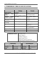
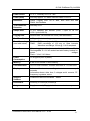
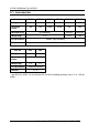
6. POWERMONIC PM20/30 SPECIFICATIONS
Voltage
Current
Input Channels
3 (isolated)
4
Measuring
(RMS)
125-440 V
0-3000 A (max with clip-on
CTs, others no limit)
Range
63-260 V available on request
Isolation
Voltage
between Channels
600 V RMS
(not isolated between CT
inputs)
Power
Frequency
40-70 Hz (50-60 Hz nominal)
40-70
Hz
nominal)
Instrument
Accuracy
0.4% reading ± 1 lsd
0.4% reading ± 1 lsd
System Accuracy
0.4% reading ± 1 lsd
1% reading
(0.5M CTs)
Resolution
0.1 V
0.1
A
(0-500
1 A (1000-3000 A)
System
Instrument Input
0-200 mA
CT Burden
2.2 Ω ± 1%
(50-60
±
1
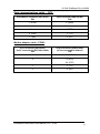
IEC 61010-1 2001
Protection Levels
Pollution Degree 2
Installation Category III
Material Group III, 600 V
Measurement Category III 440 Volts
(Double Insulation or Reinforced Insulation)
Connectors
Environmental
Voltage & Power
8 pin 30mm dia
Temperature
-10°C to + 60°C
Current
4 pin circular
Humidity
20% to 99% RH
Data
5 pin circular
Sealing
IP65
38
PowerMonic PM20/30xx User Manual V5.3 – 0704
Hz
lsd
A)