1
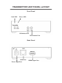
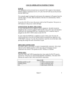
HDMIC6PRO HDBaseT Extender With Bi direction IR 100M User Manual Transmitter Receiver ASKING FOR ASSISTANCE Customer Care: Telephone Fax 1800 337 366 1800 659 963 Customer Care Hours: 8:30 AM to 5:30 PM Monday thru Friday. Write To: Pro.2 562 Spencer St. West Melbourne, VIC 3003 Australia http://www.pro2.com.au/ Notice Pro.2 reserves the right to make changes in the hardware, packaging and any accompanying documentation without prior written notice. © 2013 Pro.2, All Rights Reserved All trademarks are the property of their respective companies Rev × A CONTENTS 1. 2. 3. 4. 5. 6. 7. 8. Introduction How It Connects Features Transmitter Unit Panel Layout Transmitter Unit Panel Description Receiver Unit Panel Layout Receiver Unit Panel Description Connecting and Operating the HDMIC6PRO HDBaseT With Bi direction IR 9. Specification 10. Warranty 11. Compliance INTRODUCTION The HDMIC6PRO HDBaseT Extender With Bi direction IR 100M extends HDMI signals over just one 100 Ohm Cat.6 cable -- up to 100 meters away with no signal compression. This model supports Full HD 1080p resolution and 3D. DVI-D Computer video can also be transmitted with a DVI-to-HDMI cable or adaptor (Note: Audio is not included in a DVI-D signal). By using standard and widely available 100 Ohm Cat.6 cable, this model makes HDMI signal networking easier than larger, more expensive HDMI copper cable and more robust than optical fiber cable. HOW IT CONNECTS The HDMIC6PRO HDBaseT Extender With Bi direction IR 100M package consists of a Transmitter and a Receiver. The HDMI source (set-top box, DVD/BluRay player, gaming console, etc.) connects to the Transmitter unit. The Receiver unit connects to the HDTV display in the same way. One 100 Ohm Cat.6 cable (up to 100 meters long) links the Transmitter and Receiver. Power is applied to the Transmitter and Receiver with 5V DC power supply (included). High Definition picture and Sound are then transmitted into the HDTV screen. HDMI Source Device or HDTV display can also be controlled remotely via bi-direction IR. Note:HDMIC6PRO HDBaseT Extender With Bi direction IR 100M is HDCP 2.0 compliant. FEATURES Audio and video are transmitted digitally over the 100Ohm Cat.6 cable with no signal loss. Single Link Range: 1080p/60 and 1920x1200 Compliant with HDCP 2.0 and DVI1.1 standards Supports digital video formats in 480i, 480p, 720p, 1080i, 1080p Supports PCM 2 Ch audio, 5.1, 7.1, DTS-HD, Dolby audio format Supports bi-direction IR pass through function. HDMI source device (set-top box, DVD player and Blue ray DVD Player) can be controlled by IR at both Transmitter and Receiver end. Package Includes (1) 1 x Transmitter (2) 1 x Receiver (3) 2 x 5V DC Power Supply for Transmitter or Receiver (4) 1 x User Manual TRANSMITTER UNIT PANEL LAYOUT Front Panel Link LED Power LED IR Emitter Port IR Extender Port Back Panel RJ45 Port Power Input Port HDMI Input Port TRANSMITTER UNIT PANEL DESCRIPTION 1. Link LED This LED indicator will flash once Cat.6 cable has been properly connected between the Transmitter and Receiver unit. Once both devices are connected and powered up this LED will stop flashing and stay on to indicate successful connection between Transmitter and Receiver. 2. Power LED This LED indicator will activate once the included 5V DC power adapter has been properly connected between the Transmitter unit and a power socket. Note: the LED will blink during the initial power up time during which it is loading the device firmware. 3. IR Emitter Port Insert the IR Emitter Cable to this IR port and place the connected IR emitter module on the IR Extender zone of HDMI source (set-top box, DVD player or BluRay Player). Note: Some devices are very particular about IR emitter placement; success can be achieved by experimenting with emitter location prior to adhering the emitter to the device. 4. IR Extender Port Please connect the IR Extender cable to this port. Output device can now be controlled from the location of this transmitter unit by way of its original IR remote control or a universal type IR remote control. 5. Power Input Port Connect 5V DC power supply to this input port. 6. RJ45 Port Connect a 100Ohm Cat.6 cable between this output port and the RJ45 input port on Receiver unit. Note: For best performance, we encourage the use of Stranded CAT6A shielded cable STP (750Mhz), as a minimum though please ensure CAT6 UTP (550Mhz) cable is used or poor performance may result. 7. HDMI Input Port Connect one HDMI cable between this port and HDMI output port of the source device (DVD, Set-top box, blue-ray DVD) RECEIVER UNIT PANEL LAYOUT Front Panel Link LED Power LED IR Emitter Port IR Extender Port Back Panel RJ45 Port Power Input Port HDMI Output Port RECEIVER UNIT PANEL DESCRIPTION 1. Link LED This LED indicator will flash once Cat.6 cable has been properly connected between the Transmitter and Receiver unit. Once both devices are connected and powered up this LED will stop flashing and stay on to indicate successful connection between Transmitter and Receiver. 2. Power LED This LED indicator will activate once the included 5V DC power adapter has been properly connected between the Receiver unit and a power socket. Note: The LED will blink during the initial power up time during which it is loading the device firmware. 3. IR Emitter Insert the IR Emitter Cable to this IR port and place the connected IR emitter module on the IR Extender zone of HDTV display. Note: Some devices are very particular about IR emitter placement; success can be achieved by experimenting with emitter location prior to adhering the emitter to the device. 4. IR Extender Port Please connect the IR Extender cable to this port. Source device can now be controlled from the location of this receiver unit by way of its original IR remote control or a universal type IR remote control. 5. Power Input Port Connect 5V DC power supply to this input port. 6. RJ45 Port Connect a 100Ohm Cat.6 cable between this input port and the RJ45 output port on Transmitter unit. Note: For best performance, we encourage the use of Stranded CAT6A shielded cable STP (750Mhz), as a minimum though please ensure CAT6 UTP (550Mhz) cable is used or poor performance may result. 7. HDMI Output Port Connect one HDMI cable between this output port and HDMI input port of HDTV display. CONNECTING AND OPERATING How to Connect the HDMIC6PRO HDBaseT Extender With Bi direction IR 100M 1. 2. 3. 4. 5. Connect one HDMI Cable between the HDMI output port of source device and the HDMI input port of Transmitter unit (5 Meters Max) Connect one HDMI Cable between the HDMI input port of display device and the HDMI output port of Receiver unit. (5 Meters Max) Connect one 100 Ohm Cat.6 cable between the RJ45 port of Transmitter unit and RJ45 port of Receiver unit. Note: CAT.6 is to be no longer than 100 meters in length and should not run parallel to mains power cables. Connect 5V DC power supplies to both Transmitter and Receiver unit. Power on the display device first and then the source device. SPECIFICATION PERFORMANCE HDTV Resolution 480p,720p,1080i,1080p Color Depth 16 bit for R.G.B. each Audio Format PCM 2 Ch audio, 5.1, 7.1, DTS-HD, Dolby audio format IR Range 38kHz, 56kHz Maximum Cable Range HDMI Input: 5 meters Max HDMI Output: 5 meters Max Video Bandwidth 10.2Gbps Input Video Signal 1.2 Volts P-P Input DDC Signal 5 Volts(TTL) I/O CONNECTOR Transmitter Input Output 1x HDMI-A 19PIN Socket 1x 2.5mm DC Jack 1x RJ45 Jack 1x 3.5mm Jack for IR Emitter Receiver 1x RJ45 Jack Input 1x 3.5mm Jack for IR Receiver 1x 2.5mm DC Jack Output 1x 3.5mm Jack for IR Emitter MECHANICAL Transmitter Dimensions (H-W-D) 245x220x120mm Weight 0.4kg Receiver Dimensions (H-W-D) 245x220x120mm Weight 0.4kg WARRANTY Limited Warranty 1 Year Parts and Labor ENVIRONMENTAL Operating Temperature +0 to +40° C (+32° to 104° F) Operating Humidity 10% to 85% (Non-condensing) Storage Temperature -20° to +60° (+20° to +140° F) Storage Humidity 10% to 85% (Non-condensing) POWER REQUIREMENTS External Power Supply [email protected] SAFETY Certificate FCC, CE, RoHS Power Adapter UL, CE, FCC, RoHS, SAA WARRANTY LIMITED WARRANTY – With the exceptions noted in the next paragraph, PRO.2 warrants the original purchaser that the equipment it manufactures or sells will be free from defects in materials and workmanship for a period of one year from the date of purchase. Should this product, in PRO.2’s opinion, prove defective within this warranty period, PRO.2, at its option, will repair or replace this product without charge. Any defective parts replaced become the property of PRO.2. This warranty does not apply to those products which have been damaged due to accident, unauthorized alterations, improper repair, modifications, inadequate maintenance and care, or use in any manner for which the product was not originally intended. Our goods come with guarantees that cannot be excluded under the Australian Consumer Law. You are entitled to a replacement or refund for a major failure and compensation for any other reasonably foreseeable loss or damage. You are also entitled to have the goods repaired or replaced if the goods fail to be of acceptable quality and the failure does not amount to a major failure. Items integrated into PRO.2 products that are made by other manufacturers, notably computer hard drives and liquid crystal display panels, are limited to the term of the warranty offered by the respective manufacturers. Such specific warranties are available upon request to PRO.2. PRO.2 makes no other representation of warranty as to fitness for the purpose or merchantability or otherwise in respect of any of the products sold. The liability of PRO.2 with respect to any defective products will be limited to the repair or replacement of such products. In no event shall PRO.2 be responsible or liable for any damage arising from the use of such defective products whether such damages be direct, indirect, consequential or otherwise, and whether such damages are incurred by the reseller, end-user or any third party. In case of product defect, please contact PRO.2 Customer Care. The product is to be returned at the customer’s expense for assessment, and if replaced or repaired under warranty, will be returned at PRO.2’s expense.