1
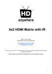
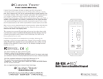
A-BUS Installation Instructions
by
A-BUS Local Source Input Module (ABUS-LS1RJ): The LIM provides “local”
input capability for sources such as TV sound, MP3 player, computer sound cards,
etc. located in the zone. The LIM automatically switches to the local input when a local
source is detected. 30-seconds after the local source ceases, the LIM automatically
reverts to the main input source. The LIM is easy to install. Note- Care should be taken
during pre-wire to run the category 5 cable from the hub to the power module via the
LIM installation point if this facility is to be made available. This is often a forgotten
requirement, e.g. In the case of local TV, the category 5 cable should be run past the
room’s aerial point.
A-BUS COMPATIBILITY:
This product complies with the A-BUS format. The A-BUS format has been adopted by
other manufacturers who make variety of products that can give your system added
flexibility. When looking to expand and/or upgrade your home entertainment system,
be sure to look for products that carry the A-BUS trademark.
RJ45 Ethernet vs.
RJ-45 Socket
Socket
Welcome to A-BUS Multi-Room Audio. When combined with our source equipment
(receiver, CD player, etc.) and speakers., A-BUS creates a versatile whole-house audio system that will fill your home with high-quality music for years to come.
A-BUS SYSTEM OVERVIEW:
A-BUS Hub (ABUS-HUB1X2, ABUS-HUB1X4): The A-BUS hub is the core of the
system, distributing audio signal, system power and status indication to A-BUS power
modules installed in rooms throughout the home and sends IR commands from the
power modules back to the source components. It is usually located near the main
sound system (Amplifier/Receiver, CD, DVD, Tape, Cable, etc.). They typically have
two or more zone outputs with expansions ports (IN/OUT) so multiple hubs can be
connected to tailor the system to individual requirements.
●Audio input from the main amplifier’s tape output or second zone output.
●4 Infrared (IR) outputs to remote controllable source components and the main amplifier (to allow for input selection). Dual emitters may be used.
●Power supply for system power (supplied). (Should not to be connected to the amplifiers switched output.)
●Status optional (see below)
●Zone outputs to go to A-BUS volume control power modules.
●Expansion ports- to add additional zones. (A-BUS - HUB1X4)
●OUT: Connects to additional hubs to add more zones or rooms. (Each hub requires
its own power supply)
●IN: connects to the direct input of an A-BUS/READY amplifier or connects to an ABUS input selector.
●Local infrared input (xantech™ compatible) to relay IR commands if the main system
amplifier is concealed (single zone amplifiers only).
A-BUS Volume Control Power Modules (ABUS-VC2RJ): A-BUS volume control
power modules are stereo amplifiers with level control that power a pair of speakers
in each room. Only one category 5 cable is required between the hub and the power
module. Speaker cable is run from the power module to the speakers except when the
A-BUS power module is located on the speaker itself. Standard rotary A-BUS power
modules do not include infrared repeating. IR-equipped modules relay 38KHz and 56
KHz codes to the source components for input track/channel selection, etc. They also
include infrared talkback and status indication. An LED indicator indicates when the
A-BUS system is on (See Power/Status below) and it flashes signifying an infrared
command has been received. The volume level on touch-button A-BUS modules can
also be operated by the ARC-40 remote control handset (supplied with ABUS-VC2RJ).
The IR repeater system is always active regardless of system status.
Audio, IR Data and Status Connections: A-BUS/READY amplifiers are equipped
with an RJ-45 A-BUS output socket enabling direct connection to either a single A-BUS
Volume Control power module for one extra zone or to an A-BUS hub for multiplezones. The A-BUS/READY outlet supplies audio, status and infrared data connection.
Some A-BUS/READY amplifiers can power one power module independently while
others require a separate power supply. The A-BUS/READY jack may also be connected to the Expansion Input of an A-BUS hub to enable multiple zones.
IMPORTANT: When purchasing a new amplifier or home theater receiver look for the
A-BUS/READY logo on the front. That means a simple RJ-45 connection on the back
immediately connects you to the whole-house system, as long as the house is wired
for A-BUS.
Power/Status: There are several ways to activate an A-BUS system. When not in
operation the A-BUS system is in standby mode. It is activated by:
●Automatic Signal Sensing (Default): The Hub automatically detects when audio signal is present and activates the A-BUS system. 30 seconds after the audio signal ends
the system returns to standby.
●Main System Sensing (Preferred): A-BUS also activates automatically when the main
sound system is switched on (including source components). A 12-volt 100-300 amp
power pack should be plugged between the main amplifier’s switched power outlet and
the hub’s Status input.
●A-BUS/READY: The hub can be directly connected to an A-BUS/READY amplifier
via the Expansion Input port. The A-BUS system automatically powers up when the
A-BUS/READY amplifier is switched on. This may be done via remote control from any
room. Note: The hub power supply is still required.
8 7 6 5
4 3 2 1
8 7 6 5
Pin Signal Function
4 3 2 1
Pin Signal
Function
24v +ve
8
NC
Not Connected
Brown
8
24v
7
NC
Not Connected
Brown & White
7
GND
Ground
6
RX-
Receive -ve
Orange
6
RCH
Right Channel
5
NC
Not Connected
Blue & White
5
STAT
Status
4
NC
Not Connected
Blue
4
SIG
Signal
3
RX+
Receive +ve
Orange & White
3
GND
Ground
2
TX-
Transmit -ve
Green
2
LCH
Left Channel
1
TX+
Transmit +ve
Green & White
1
GND
Ground
Comparison of an A-BUS™ Input against a standard RJ-45 Socket
PRODUCT INSTALLATION NOTES:
●All A-BUS RJ-45 connectors are wires to the 568A standard.
●The colour code order of punchdown connectors may vary.
●Standard CAT5 patch leads may be used.
●The infrared system will relay 38kHz and 56 kHz commands.
IMPORTANT: Substitute power supplies are not recommended.
Pre-Wiring: All cabling between the A-BUS/READY amplifier/interface module, distribution hubs and power modules should be category 5 cable or better. The recommended maximum cable run is 100 feet (30m). Speaker wire should be run from the
power module point to the speaker points; however, it is recommended that the category 5 by extended to the speaker points as well to allow for the installation of an ABUS/direct speaker system which has the power module incorporated in the speaker.
A-BUS power modules will accept up to 14 gauge cable. It is recommended to extend
the category 5 cable past the power modules to the speaker points for future requirements. It is recommended that all category 5 cables at the hub end be terminated
with wall mounted RJ-45 sockets with standard (568A) patch leads between the wall
socket and the hub.
Before installing the category 5 cables check for Local Input Module requirements.
Eg. in the case of a local TV, the CAT5 cable should be run past the room’s antenna
connection point. A 12” taped loop of cable for access is recommended. The same
could be applied to a point in a child’s room next to a desk where a computer or MP3
player may be located.
IMPORTANT: These instructions contain directions for installers of A-BUS systems.
The manufacturer or its agents shall not be liable to any person or entity for loss or
damage, including consequential loss or damage, arising out of any error or fault in the
installation of the A-BUS system or any of its components parts.
IMPORTANT INSTALLATION GUIDELINES:
Before installation, review the manuals included with each component in your system.
If you are unsure of any of the installation procedures, it is recommended that you
contact your dealer or a professional electronics installer. During installation, do not
connect power to the hub. Before powering up the system, make sure all volume levels
are on minimum level. Note- before installing the power modules into the walls be sure
to adjust the trim pots after all modules have been connected. The power modules
should be installed into standard UL/CSA approved electrical J-Boxes.
21A8328
SETUP:
The A-BUS installation should be completed with all power modules connected but not installed into the walls. Follow these steps to give you maximum control flexibility over
the volume of your A-BUS system. On the back of the power modules there are trim pots (Left & Right) that fine tune the output level to compensate for the length of the cable
run, the efficiency of the speakers and size of the room. There are also situations where you may want to limit the output level in a particular room. With the trim pots adjusted to
minimum, the main volume control should be adjusted to maximum level, then with popular music playing the trim pots should be brought up to a point just below the amplifier’s
clipping level. (Clipping is the point where the sound starts to distort). When the trim pots are all set to the desired level the installation maybe completed.
STANDARD SYSTEM
IR
SOURCE1
SOURCE1
IR
IR
SOURCE2
SOURCE2
IR
AMP
AMP
TV
SPEAKER
IR
RIGHT
VOLUME CONTROL MODULE
STATUS
HUB
SPEAKER CABLE
LOCAL INPUT MODULE
SPEAKER OUT
L+ L- R- R+
CAT-5 CABLE
POWER
12V POWER
24V POWER
R AUDIO L
LINE LEVEL AUDIO
APS-40
LINE LEVEL AUDIO
CAT-5 CABLE
CAT-5 CABLE
MP3
PC
SPEAKER
TO
ADDITIONAL
HUBS
OUT EXPANSION IN
LEFT
INFRARED
INFRARED
A-BUS/READY
TRIM POTS
RIGHT
LEFT
V+
IR EMITTERS
GND
A-BUS OUTPUTS
SIG
TM
STAT
LOCAL IR
CAT-5 CABLE
FAULT FINDING:
●Most faults occur as a result of incorrect wiring.
●Check all connections carefully.
●Make sure all speakers are wired in phase.
●Disconnect power modules from hub and check operation one by one.
●A short in a line or incorrect wiring will cause the power module to shutdown until the fault is
fixed.
●Status indicates the system is active. (LED indicator on infrared models only)
Infrared: Your A-BUS infrared relay system is world standard using the most up-to date technology.
However, some infrared codes may present problems. Make sure the infrared emitters are properly
placed on the IR receiver of the source components. Infrared systems are more likely to give trouble
as a result of too much power. (Try moving the emitter away from the component). Cable boxes and
Plasma screens often cause difficulties.
RJ-45 Connection Details
Connection shown:
flat side on top
push-clip on the bottom
87
65
43
21
push-clip
FEATURES AND SPECIFICATIONS:
VOLUME CONTROL POWER MODULES (ABUS-VC2RJ)
Speakers
Drives 1 pair of speakers (4/8 ohms)
Control
Touch button up and down
Remote controllable volume level
Remote control included
Wall Plate
Designed to fit Decora™ style wall plates
Terminals
Input/CAT5 RJ-45 Output: setscrew terminal (up to
14ga)
IR
38kHz and 56kHz
Nominal range
in sunlight<15ft(5m), Indoors>60ft(20m)
Status
System ON indicated by LED
Talkback
LED flashes when in use
Dimensions
2.8”(70mm)D x 4.2”(107mm)H x 1.7”(44mm)W
LOCAL SOURCE INPUT MODULE (ABUS-LS1RJ)
Auto turn-on when local audio signal is sensed.
Auto return 30 seconds after audio ceases.
Inputs
Local Audio - RCA phone jacks (1pr)
From Hub - Cat5 RJ-45
Output
to VC power module - Cat5 RJ-45
Dimensions
1.8”(25mm)D x 4.2”(107mm)H x 1.7”(44mm)W
REMOTE CONTROL (ABR-40)
A-BUS miniature remote control included with ABUS-VC2RJ
Inputs
Buttons - Up/Down
Zone 1-4, off, All off
Battery
3VDC Lithium CR2024
Dimensions
3.4”(86mm)H x 1.3”(33mm)W x 0.3”(6.8mm)D
HUBS (ABUS-HUB1X2, ABUS-HUB1X4)
Inputs
Audio - RCA phone jacks (1pr)
Power - 2.5mm DC (+v center)
Status - 2.1mm DC (+v center)
Expansion - RJ-45 (ABUS-HUB1X4)
Outputs
A-BUS ports - 4 RJ-45
IR - 4 x 2.5mm TRS jacks
Expansion - RJ-45 (ABUS-HUB1X4)
Wiring format
568A
Dimensions
ABUS-HUB1X4
3.3”(83mm)D x 1.2”(30mmH x 7.25”(184mm)W
ABUS-HUB1X2
2.4”(61mm)D x 1.2”(30mm)H x 5.3”(135mm)W
Power Supply
APS-40 (ABUS-HUB1X4) - 120-240VAC 50/60Hz 4A
APS-23 (ABUS-HUB1X2) - 120-240VAC 50/60Hz 2.3A
CABLE REQUIREMENTS - Interface VC power module to HUB use Category 5 (or equivalent) VC power module to speakers: up to 14-gauge recommended.
A-BUS by MTX AUDIO products purchased in the United States from an authorized MTX dealer are guaranteed against defects in material and workmanship for a period of two years from the date purchased by the end user, and limited to the original retail purchaser of the product. Product found to be defective during that period will be repaired or replaced by MTX at no charge. This warranty is void if it
is determined that unauthorized parties have attempted repairs or alterations of any nature. Warranty does not extend to cosmetics or finish. Before presuming a defect is present in the product, be certain
that all related equipment and wiring is functioning properly. MTX disclaims any liability for other incurred damages resulting from product defects. Any expenses incurred in the removal and reinstallation
of products are not covered by this warranty. MTX's total liability will not exceed the purchase price of the product. If a defect is present, your authorized MTX dealer may be able to effect repairs.
Proof of purchase is required when requesting service, so please retain your sales receipt and take a moment to register your product online at mtx.com.