1
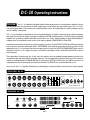
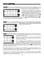
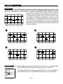
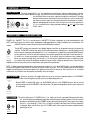
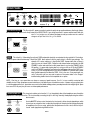
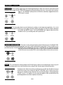
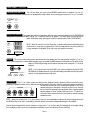
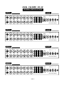
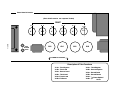
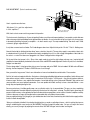
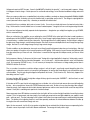
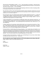
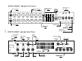
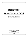
MESA BOOGIE
DUAL CALIBER DC -10
The Spirit of Art in Technology
1317 Ross Street Petaluma, CA 94954
Hello from the Tone Farm...
You, smart player and all around intuitive human, have put your trust in us to be
your amplifier company. This is something we do not take lightly. Our reward is that
we’ve designed and built another fine guitar amplifier that is destined to become a
classic. By purchasing and choosing this unit to be a part of your musical voice, you
have become part of the Mesa family...WELCOME! Our goal is to never let you down.
Your reward is that you are now the owner of a great amp, bred of fine all tube amp
heritage...benefiting from the many pioneering and patented Mesa circuits that led to
the refinement of your new instrument. Feel confident, as we do, this amp will inspire
many hours of musical satisfaction and lasting enjoyment. It was built with you in
mind, by players who know the value of a fine musical instrument and the commitment it takes to make great music. The same commitment to quality, value and support we make to you...our new friend.
Your MESA/Boogie Amplifer is a professional instrument. Please treat it with respect and operate it properly.
USE COMMON SENSE AND ALWAYS OBSERVE THESE PRECAUTIONS:
Do not expose amplifier to moisture, rain or water,
direct sunlight or extremely high temperaturres.
Always insure that amplifier is properly grounded.
Always unplug AC power cord before changing fuse
or any tubes.
Avoid direct contact with heated tubes.
Insure adequate air circulation behind amplifier.
Keep amplifier away from children.
Besure to connect to an AC power supply that meets
the power supply specifications listed on the rear
panel of the unit.
If there is any danger of lightning occurring nearby,
remove the power plug from the wall socket in advance.
To avoid damaging your speakers and other playback equipment, turn off the power of all related
equipment before making the connections.
Do not use excessive force in handling control buttons, switches and controls.
Remove the power plug from the AC mains socket if
the unit is to be stored for an extended period of
time.
YOUR AMPLIFIER IS LOUD! EXPOSURE TO HIGH SOUND VOLUMES MAY CAUSE
PERMANENT HEARING DAMAGE!
No user serviceable parts inside. Refer service to qualified personnel. Always unplug
AC POWER BEFORE REMOVING CHASSIS.
EXPORT MODELS: Always insure that the unit is wired for the proper voltage.
Make certain grounding conforms with local standards.
READ AND FOLLOW ALL INSTRUCTIONS OF PROPER USAGE.
Precautions __________________________________________________________________________ 0
FRONT PANEL: Description & Usage_____________________________________________________
Gain ________________________________________________________________________________
Treble _______________________________________________________________________________
Mid _________________________________________________________________________________
Bass ________________________________________________________________________________
Presence ____________________________________________________________________________
Reverb ______________________________________________________________________________
Master ______________________________________________________________________________
Graphic EQ __________________________________________________________________________
Mode Select __________________________________________________________________________
Level Control _________________________________________________________________________
Toggle Switches: 100 / 60 WATT: ON / STANDBY: A.C. POWER: _____________________________
1
2
3
3
3
4
4
4
5
5
5
6
BACK PANEL: Description & Usage
A.C. Receptacle_______________________________________________________________________ 7
Fuse ________________________________________________________________________________ 7
Headphone Out _______________________________________________________________________ 7
EQ Assign ___________________________________________________________________________ 8
Recording ___________________________________________________________________________ 8
FX Loop: Send & Return _______________________________________________________________ 8
FX Mix ______________________________________________________________________________ 8
Reverb & Footswitch __________________________________________________________________ 9
Silent Recording ______________________________________________________________________ 9
Slave Out ____________________________________________________________________________ 9
Speakers ____________________________________________________________________________ 9
Factory Sample Settings ______________________________________________________________ 10
Personal Settings Page _______________________________________________________________ 11
Tube Task Chart _____________________________________________________________________ 12
Tube Noise & Microphonics ___________________________________________________________ 13
Diagnosing Power Tube Failure ____________________________________________________ 13 & 14
Diagnosing Pre-Amp Tube Problems ____________________________________________________ 15
Bias Adjustment ____________________________________________________________ 16 & 17 & 18
Parts Sheet _________________________________________________________________________ 19
DC-10 Operating Instructions
Overview:
Your DC-10 amplifier was designed to deliver maximum performance in a format based on simplicity. Its easy to
dial nature allows each of the two channels to deliver a wide range of sounds in both clean and overdrive styles. This Dual Caliber
uses four 6L6 power tubes to fuel its healthy one hundred watt power section. We are pleased by its surprising headroom, yet truly
musical “clipability” when pushed.
The DC-10’s pre-amp was no afterthought as you may have deduced by the six 12AX7s tucked snugly away under the swing away
tube clamp. Two separate sets of tubes are used to accomplish the RHYTHM and LEAD channels. It’s really like having two separate
amplifiers that can produce 4 different switchable sounds built into one chassis. Ultimate flexibility is achieved by providing two
complete sets of Tone and Master controls as well as the channel assignable 5 BAND GRAPHIC EQUALIZER.
Looking to the rear panel assures that all your interfacing needs are covered. A Parallel EFFECTS LOOP with a MIX control provides
tone insurance for even those questionable effects. A RECORDING circuit dialed for direct to board sessions provides accurate
reproduction of the DC-10’s pre-amp. When the session goes late into the night, the SILENT RECORDING MUTE switch comes in
real handy. To use the DC-10 in larger rack systems, or to interface to other power sections, the SLAVE jack and LEVEL control are
welcome features.
Three combinations of speaker jacks (one 16 ohm, two 8 ohm and two 4 ohm) are provided for proper impedance matches to the
many different types and makes (brands) of speaker enclosures. The mini-toggle switch located next to the fuse on the rear pane l,
enables you to decide whether the 5 BAND GRAPHIC EQ enhances the RHYTHM & LEAD channel, the LEAD channel only, or an
assignable position that can be remotely controlled via the footswitch. The REVERB can also be footswitched in or out.
As you can see, the DC-10 provides all the features any demanding pro could need and at the same time remains simple to operate.
FRONT VIEW DC-10
65
65
1 0 10
1 0 10
1 0 10
1 0 10
987
65
987
65
987
65
987
65
987
65
987
65
987
43 2
1 0 10
43 2
1 0 10
43 2
1 0 10
43 2
MASTER
43 2
REVERB
43 2
PRESENCE
32
65
BASS
ON
60 WATTS
STANDBY
98 7
MID
ON
10
TREBLE
100 WATTS
FT.SW.
10
GAIN
43 2
RHYTHM
4
43 2
43 2
43 2
43 2
65
43 2
1 0 10
987
43 2
1 0 10
987
987
987
43 2
1 0 10
65
1 0 10
65
1 0 10
987
987
987
FOOT
SWITCH
1 0 10
65
1 0 10
65
INPUT
LEAD
LEAD + EQ
80Hz
240
750
2200
LEVEL
POWER
DUAL CALIBER DC-10
6600
65
REAR VIEW DC -10
1.5 A
FUSE
RHYTHM & LEAD
EQ FTSW
ASSIGN
SLAVE
10 0%
0%
120 V.
3 A.
60 HZ.
AC POWER
3 A SB
LEAD ONLY
SEND
FX MIX
HEADPHONES
RECORDING
REV FTSW
RETURN
SPEAKERS
MUTE SPKR ON
SILENT RECORDING
PAGE 1
16 OHM
8 OHM
8 OHM
4 OHM
4 OHM
FRONT PANEL:
INPUT
5
5
2
6
4
3
4
FT.SW.
FOOT
SWITCH
100 WATTS
RHYTHM
GAIN
TREBLE
MID
BASS
PRESENCE
REVERB
MASTER
6
5
4
5
2
2
4
LEAD
LEAD + EQ
80Hz
240
750
2200
6600
ON
ON
2
LEVEL
60 WATTS STANDBY POWER
DUAL CALIBER DC-10
First familiarize yourself with the layout of the front panel and locate the RHYTHM / LEAD + EQ switch on the right side of the chassis,
between the 5 Band Graphic EQ and MASTER LEVEL control. This toggles you between the top (RHYTHM) channel and the bottom
(LEAD) channel. If you don’t have the RHYTHM / LEAD + EQ Footswitch connected, this switch will activate the channel switching
function. Before we get critical about each control, let’s audition the two channels with a basic clean setting in the RHYTHM channel
and a fairly high gain overdriven sound in the LEAD channel.
POWER-UP: Connect your guitar to the Instrument INPUT jack. Flip the POWER switch ON while leaving the STANDBY switch
set to STANDBY. (It’s always a good idea to practice this start up procedure as at least 30 seconds of warm-up time lessens the shock
on cold power tubes, thus prolonging their toneful life substantially.) Next set the controls and the Graphic EQ as shown above:
Flip the STANDBY switch to the ON position and listen to the two channels using either the footswitch or the
Channel Select toggle switch found on the right side of the front panel. The EQ Footswitch Assign located
on the left side of the rear panel (next to the fuse), controls the EQ assignment. This popular “V” type curve
works well in both RHYTHM and LEAD channels, but most players tend to use it more in the LEAD channel,
finding the RHYTHM plenty sweet by itself - without the use of the EQ. (see page 5 for more information on
EQ)
RHYTHM & LEAD
FUSE
3 A SB
EQ FT.SW.
ASSIGN
LEAD ONLY
RECORDING
Again, these are merely examples of the two channels. Experimentation leads to finding many different
sounds in each channel and understanding the controls and the way they interact, can make this much easier and more fun.
Now that you have heard the DC-10’s two channels, let’s move on to understanding the controls and their interactive roles in
achieving the sounds that you want to hear.
CONTROLS:
GAIN: This is by far the most powerful control in each channel. It not only determines the overall gain amount, shape and
sensitivity of the channel...but it is also a powerful Tone control. Generally speaking, whatever is dialed here ultimately determines the
channels personality. Set low, it allows cleaner, brighter sounds with enhanced dynamic response, especially in the higher frequencies. Set high the whole personality of the channel becomes darker, fatter and more overdriven.
INPUT
5
In the DC-10 we worked hard to make sure the entire range of GAIN available is usable and more
importantly, musical. Don’t think for a moment that this simple one knob layout limits you as to the amount
FOOT
GAIN
and texture of GAIN. Long neurotic hours were spent to ensure the ranges of GAIN were stylistically
SWITCH
4
accurate. It’s probably a good time to mention that most of the great sounds can be found by setting the
GAIN control moderately, especially in the LEAD channel. For example, somewhere between 2 thru 6 .
In the RHYTHM channel try setting this control somewhere between 3 thru 8 . Use of moderation here
will reduce the likelihood of pesky microphonic tube problems ever occurring, while at the same time
making the two channels easier to balance in relative listening volume and effects send signal strength.
PAGE 2
CONTROLS:
(Continued)
TREBLE: As with most guitar amplifiers, the TREBLE control is the strongest of the three rotary tone controls. It adjusts the blend
of high frequencies in a wide band between the midrange and presence frequency ranges. Its setting on the DC-10 also determines
the blend and strength of the MIDDLE and BASS controls. Set high, it is the dominant control, minimizing the amount of MID and
BASS that would be possible in the mix. Set low, the TREBLE becomes the recessive control and
a warmer, darker blend is produced. Dial with care. Subtle tweaking of this control tends to
INPUT
5
produce the best results.
FOOT
SWITCH
GAIN
TREBLE
5
MIDRANGE Your new Dual Caliber uses a unique MIDRANGE circuit that not only blends in rich warm MIDRANGE, but goes
beyond to give you an added bonus. Through endless daily tone dreaming, the “if-only” design dictum led to the dial-in-gain boost
MIDDLE control. In the DC-10 a third over the top crunch sound was made possible by the inclusion of the RHYTHM channels dual
purpose MID control.
From 0 to about 3 the taper is adjusted to act as a very effective MID control. As
you increase the MID to 4 and above, you will hear the lower MIDS getting more
pronounced and fatter. At about 6 the MID leaves behind the old notion of being a
tone
control and becomes a truly usable gain control. This upper range is a smokin’
GAIN
TREBLE
MID
FOOT
addition
to the RHYTHM channel’s GAIN control for all kinds of higher gain rhythm
SWITCH
5
sounds. Try the MID set high and the GAIN control at about 6
7 for a cool blues
solo sound. If this still isn’t crazy enough for you...Max the GAIN and TREBLE controls
and set the PRESENCE control to 0 or 1 , turn on the Graphic and give it the old
“V” curve. Then plug the DC-10 into a 4x12 with some Celestion Vintage 30’s or 25’s.
This should be sufficiently heinous for even the most serious crunch fiends. The versatility that this dual purpose MID control lends to
the RHYTHM channel greatly expands its usefulness as both a clean and overdrive channel.
INPUT
2
NOTE: The lower region of the MID control determines midrange punch and boldness in lower gain sounds and a smooth vocal
blend in high gain sounds. It can be very effective acting as a “cut through the band control” in certain situations. Dial to taste,
remembering that the setting of the TREBLE control greatly effects this controls’ strength. To obtain the sweetest clean sound, set the
Mid to 2 or below.
BASS: This control blends in the lower frequencies and its effectiveness, again, depends on the setting of the TREBLE control. It
should be set with moderation as extreme settings in either low or high directions can produce an unbalanced tone. Be “especially”
careful in higher GAIN settings of either channel. Too much BASS will cause a flabby unfocused sound that can’t be dialed out with
the graphic because excessive BASS has been introduced to the pre-amp in
the early stages.
INPUT
FOOT
SWITCH
6
GAIN
TREBLE
MID
BASS
5
Try setting the BASS to 6 for clean sounds in the RHYTHM channel and
4 or below when dialing up high gain overdriven sounds in this channel. In
the LEAD channel, try setting the BASS somewhere between 3 and 6 .
These settings will vary with the amount of GAIN and TREBLE you have
dialed up.
PAGE 3
CONTROLS:
(Continued)
PRESENCE: These controls attenuate the upper high end harmonics and control dynamic compression in the power section. High
settings produce more sparkle and cut, lending a more open quality to the channel. Low settings of the PRESENCE compress the
sound and enhance the more vocal qualities of single notes.
INPUT
3
This control can also produce a fatter, warmer character, especially
in the LEAD channel. Lower TREBLE settings, combined with low
MID
BASS
GAIN
TREBLE
PRESENCE
FOOT
PRESENCE settings produce the richest, roundest lead sounds. Try
SWITCH
2
setting the RHYTHM channels’ PRESENCE control at around 5
or 6 for the sweet blend of sparkle and cut. This range in the
RHYTHM channel also tends to give the impression of more headroom. Try a LEAD channel PRESENCE control setting of 3 to
start with and adjust to taste. Avoid setting the LEAD PRESENCE control to 10 when high GAIN and TREBLE settings are in use.
This reduces the likelihood of annoying microphonic tube problems.
REVERB: The DC-10 has a separate REVERB control for each channel. This enables different amounts of the rich ALL TUBE
REVERB to be mixed with the dry signal of each channel without compromise. It is normal for extreme settings of the REVERB control
to slightly alter the character of the channel as the voicing of the REVERB
INPUT
circuit becomes more dominant in the mix.
6
FOOT
SWITCH
GAIN
TREBLE
MID
BASS
5
MASTER: The individual channel MASTER controls serve three purposes in the layout of the DC-10. FIRST: They serve as level
balancing controls for each of the two channels. This enables a wide range of front end gain settings to be matched to a given listening
level and the level of the other channel.
4
BASS
PRESENCE
REVERB
MASTER
4
SECOND: They act as Effects Send controls, for each channel, in the EFFECTS LOOP.
As with many of the controls on the DC-10, the best results for balance and tone are
usually found in the medium range.
THIRD: The MASTER control is the RECORDING jacks’ Send Level control. When
using the direct RECORDING jack found on the rear panel to interface directly to a
mixing board or recorder, this control will determine the amount of signal you will be
sending via this jack. In this application it is usually best to start with the MASTER controls set to 0 and gradually increase them to
the proper level. This minimizes the possibility of blowing speakers or eardrums in the event the engineer has an extremely sensitive
input headroom setting in place at the console.
NOTE: When trying to use your DC-10 at extremely low volume levels it will be necessary to reduce the far left GAIN control. Once
the MASTERS and output LEVEL have been reduced to roughly 1.5 , reducing the MASTERS or output LEVEL below this point
causes phase interaction that prevents a clean signal from passing through this circuit junction.
If you must use your DC-10 at whisper levels to practice late at night etc...get used to reducing the GAIN as well as the MASTERS
and output LEVELS. This effect is most noticeable in the RHYTHM channel set for a crystal clean sound. In the LEAD channel set for
a high gain sound the interaction effect is less noticeable.
PAGE 4
CONTROLS:
(Continued)
GRAPHIC EQ:
The 5- BAND GRAPHIC EQ provides limitless additional shaping of the already curvaceous tone. It is bypassable and channel assignable. These assignment choices are menued on the rear panel around the mini-toggle switch (located
next to the fuse. The three choices are: “RHYTHM & LEAD” - LEAD ONLY - and EQ FOOTSWITCHABLE / ASSIGN. The GRAPHIC
is not a necessity to amazing tone, but can greatly enlarge the scope of sonic
possibilities. If you never turned it on you would still have one of the most amazing sounding amps around...but it’s there...so you may as well take a crack at
some tweaking. One setting that keeps popping up as a classic Boogie EQ
curve is the fabled “V”. This setting increases the bottom, scoops the mids and
leaves the highs to do their harmonic best. Be sure to try this at some point as
many Boogie users have found it to be their main sound due to its wideness and
spread. Below are some other sample settings that we see used quite often, but
by all means experiment.
80Hz
240
750
2200
6600
1.
2.
80Hz
240
750
2200
6600
80Hz
240
750
2200
6600
80Hz
240
750
2200
6600
4.
3.
80Hz
240
MODE SELECT:
750
2200
6600
This three position toggle switch located on the front panel lets you access the DC-10s’ three different mode
choices when you do not have the Footswitch connected or there isn’t one available.
The choices are RHYTHM (up), LEAD (center) and LEAD+EQ (down). To use the CHANNEL SELECT FOOTSWITCH - make sure the MODE SELECT toggle is in the center (LEAD) position.
RHYTHM
FT.SW.
LEAD
LEAD + EQ
LEVEL
6600
PAGE 5
CONTROLS: (Continued)
LEVEL CONTROL: This lonely knob is the DC-10’s final output knob or overall master. After the relative balance of the two
channels has been set with the channel MASTER controls, use the LEVEL control to increase or decrease the listening volume. It is
also the Effects Return Level control, a point we thought you should know. This design
element makes processor interfacing a lot easier and gives you one less knob to deal
ON
100 WATTS
RHYTHM
with when you want to adjust your overall playing volume in performance situations.
10
Optimum setting depends on the size of the room you wish to rock, but generally the
DC-10 sounds best with a setting somewhere between 2 and 6 on the output
LEVEL control.
60 WATTS
STAND
LEAD + EQ
LEVEL
FT.SW.
4
65
6600
987
32
10
LEAD
DUAL CALIBER
FRONT PANEL: TOGGLE SWITCHES
POWER: 60 / 100 WATT: The DC-10 may be used in a 100 WATT (Full Power) configuration or can be switched down to a 60
WATT (Half Power) harness for smaller venues, added power clipping possibilities or, simply for different sonic characteristics. The
100 WATT position sounds fuller and richer with more defined bass response.
100 WATTS
The 60 WATT position leans towards a more bubbly, brighter sound that can be pushed more easily for power clip
overdrive. The 60 WATT position shuts down the two center power tubes, keeping them in stand-by mode for instant
power increases and may be switched while the DC-10 is in operation. If you prefer the sound of the 60 WATTposition
you may feel free to use it all the time with no penalty. You may then swap the two center 6L6’s for the outer pair in 6 60 WATTS
12 months or so, in order to prolong the re-tubing intervals. In the unlikely event you should ever have a power tube
DUAL
failure, you may pull the faulty tube(s) and run the DC-10 with only the outside pair until you can replace the faulty
tube(s).
If you ever have to resort to this procedure, be aware that you will notice a slight hum, but don’t worry...it won’t hurt your
amplifier at all and will cease when you have replaced the center pair with two good tubes.
NOTE: To obtain the maximum headroom for clean sounds when using the DC-10 in the 60 WATT position, it is recommended that
you remove the speaker cable from the 16 ohm jack and connect it to the 8 ohm jack. This is not mandatory, but will insure the best
impedance match giving you the maximum power. If you prefer the sound of the 16 ohm jack or wish to clip the DC-10 at reduced
volume levels...by all means leave the speakers connected to the 16 ohm output.
ON / STANDBY: Perfect for set breaks...this toggle switch also serves an even more important purpose. In the STANDBY
position the tubes are at idle so that during power up they may warm up before being put to use.
ON
Before POWER is switched ON, make sure the STANDBY switch is in the STANDBY position. Wait at least 30
seconds and then switch the STANDBY to the ON position. This prevents tube problems and increases their toneful
life substantially.
STANDBY
CALIBER
A.C. POWER:
ON
This switch delivers the A.C. POWER to the DC-10. Make sure the unit is grounded (All three terminals of the
A.C. cord should be connected whenever possible) and that the proper voltage is present. Follow the cold start
procedure as described in the ON / STANDBY section above when powering up. The total power consumption
for the DC-10 is 3 Amps @ 117 Volts. Thus, a 15 Amp circuit (which is what most house circuitry is wired with)
is adequate. Make sure the Euro style A.C. POWER cord is firmly seated in the power receptacle before
powering up the unit.
POWER
DC-10
PAGE 6
REAR PANEL:
WARNING:
Unplug power
before replacing
fuse or removing
bolts mounting
chassis.
1.5 A
RHYTHM & LEAD
FUSE
EQ FTSW
ASSIGN
SLAVE
10 0%
0%
3 A SB
LEAD ONLY
SEND
FX MIX
HEADPHONES
RECORDING
REV FTSW
RETURN
120 V.
3 A.
60 HZ.
SPEAKERS
MUTE SPKR ON
SILENT RECORDING
16 OHM
8 OHM
8 OHM
4 OHM
4 OHM
A.C.RECEPTACLE: This Euro style A.C. power connection is perfect for quick set-ups and break-downs after the gig. Always
be sure that the A.C. power cord is firmly seated in the RECEPTACLE. If you should loose the A.C. power cord that comes with your
new DC-10, just give us a call and we’ll be happy to send you another one for a nominal
charge or see your local Mesa/Boogie Pro Center.
WARNING:
Unplug power
before replacing
fuse or removing
bolts mounting
chassis.
FUSE
3 A SB
HEADPHONES
120 V.
3 A.
60 HZ.
FUSE: This is the A.C.s’ (Alternating Current) main FUSE and provides electrical current protection from outside A.C. fluctuations,
as well as power tube failure damage. Should the FUSE blow, replace it with the same rating in a Slo-Blo type package. The
domestic U.S. version requires a 3 Amp Slo-Blo FUSE. A power tube short or failure is
WARNING:
often the cause of a blown FUSE...Follow the cold start procedure mentioned in the ON/
Unplug power
before replacing
FUSE
STANDBY section and watch the four 6L6 power tubes as you turn the STANDBY to the
fuse or removing
bolts mounting
ON position. If a power tube is going bad or is arcing you will see it! Flip the STANDBY
chassis.
3 A SB
switch to STANDBY immediately and replace the faulty power tube and the FUSE if necHEADPHONES
essary. If you see nothing abnormal as you lift the STANDBY, it is possible that a power
tube shorted temporarily and blew the FUSE. If this is the case, it may work again nor120 V.
3 A.
mally. To be extra safe you may want to replace all four power tubes in the “shotgun”
60 HZ.
troubleshooting tradition and save the replaced set as spares.
NOTE: Like tires on a car, spare tubes are always a measure of good insurance. Your DC-10 was carefully constructed with
reliability in mind! Given the proper care and maintenance, it will deliver years of trouble free service. However, any pro guitarist who
is out there gigging will tell you; spare tubes are a must for the fabled cord bag and may someday be worth their weight in gold. Spare
fuses are also a very easy way to insure an uninterrupted performance.
HEADPHONE OUT:
This stereo jack enables you to hear the DC-10 through both sides of the headphones even though the
amplifier has a mono power section. This is achieved by connecting the “tip” to the “ring” internally, thereby duplicating the sound in
both channels.
FUSE
EQ FTSW
ASSIGN
3 A SB
LEAD ONLY
HEADPHONES
RECORDING
Use the MASTER volume control located on the front panel in either channel depending on which
channel you are using at the time, to adjust the listening level. Keep in mind that the type and quality
of headphones that you are using, greatly affect the performance of this circuit, with the fully enclosed - studio type producing the best results.
PAGE 7
REAR PANEL: (continued)
EQ ASSIGN: This two position toggle assigns the 5-Band Graphic Equalizer to either of the channels and overrides the EQ
Footswitch. With the toggle in the RHYTHM & LEAD (up) position the Equalizer will be on all the time. As you might surmise, when the
toggle is in the LEAD ONLY (down) position the EQ will be automatically engaged whenever the
LEAD channel is selected.
RHYTHM & LEAD
EQ FTSW
FUSE
ASSIGN
LEAD ONLY
3 A SB
RECORDING
HEADPHONES
RECORDING: This jack provides direct-to-console interfacing for recording or sound reinforcement applications. It is a circuit
dedicated to reproducing the roll off that occurs in the output section with a speaker connected. The send level strength is determined
by the GAIN and MASTER controls. From the RECORDING jack, adequate signal level will be
available for most of your recording needs and live performances.
FUSE
EQ FTSW
3 A SB
ASSIGN
LEAD ONLY
HEADPHONES
RECORDING
FX LOOP: SEND / RETURN: These two 1/4" jacks are the patch point for external effects processors. The EFFECT LOOP
is a patch point between the pre-amp and power section and is wired in parallel with the normal signal. Connect the SEND jack to
your effects Input jack. Connect the RETURN jack to the Output jack of your effect. The RETURN jack can also double as a Power
Amp Input jack. When the RETURN jack is used as an input, only the 5 Band EQ, the PRESENCE
control of the active channel and the LEVEL control are being utilized, all other controls are inactive.
0%
SEND
FX MIX
REV FTSW
RETURN
FX MIX: This control determines the dry/wet blend of the FX LOOP signal in relation to the unaffected signal. Set to 0% you will
experience only the dry signal (none or very little effect) and at a setting of 100% the entire signal will be wet (total effect.)
0%
SEND
FX MIX
REV FTSW
RETURN
For the best results...Set the mix control of your effect processor to 100% wet. Then dial in the amount
of effect that you wish to hear, starting at 0% with the FX LOOP MIX control. The drier (closer to 0%)
signal you use, the better your tone should be. This is one of the advantages in having a parallel type
FX LOOP in your DC-10 amplifier...this circuit allows the amplifier to retain its purity with the least
possible degradation due to effects impedance mismatching.
PAGE 8
REAR PANEL: (continued)
REVERB FOOTSWITCH: This 1/4" jack allows you control of the REVERB remotely when the (optional) Mesa/Boogie
Footswitch is connected. This footswitch can be ordered by calling us direct, or by contacting your nearest Mesa/Boogie Pro Center.
0%
10 0 %
SEND
FX MIX
REV FTSW
RETURN
SILENT RECORDING: This rocker switch which is located down under the chassis and selects between the live SPEAKER ON
setting and the silent SPEAKER MUTE setting. This is a perfect solution for all-nighters! This switch mutes all of the signal at the
power section driver stage, removing the need for a speaker load IN THIS POSITION ONLY!
NOTE: When this switch is set to the ON position, a speaker load must be maintained by either
a load resistor of some type or a speaker itself. Failure to comply with this instruction could result
in major damage to the amplifier. To be safe Leave your speaker connected !
100 %
FX MIX
RETURN
MUTE SPKR ON
SILENT RECORDING
SLAVE: This 1/4" jack and control provide a signal derived from the speaker jack. This works great for using the DC-10 as a
master send to a processor or when additional power amps are needed for additional power. Some players use this patch point to
derive an FX Send Signal and go to other amps for their wet sound, leaving the DC-10 dry for
definition.
SLAVE
SPEAKERS
NOTE: Once a signal is taken from the SLAVE it can not be inserted back into the FX LOOP
RETURN jack or a feedback loop will occur. Much like holding a microphone into the PA system’s
cabinets...a loud high pitched squeal will result.
SPEAKERS:
The DC-10 Combo contains two 90 watt custom designed Celestion speakers and these are wired in series,
producing an impedance load of 16 ohms. Obviously the optimum speaker connection scheme for headroom and power would be the
16 ohm jack, but feel free to try connecting the speakers to any of the
SPEAKERS
speaker output jacks. Sometimes a mismatch will lend a sonic character
that you may find interesting or even preferable. When using two speaker
cabinets rated for 16 ohms, it will be necessary to use a “Y” cable to connect both of these loads to the 8 ohm jack in order to maintain a proper
4 OHM
8 OHM
8 OHM
4 OHM
16 OHM
impedance match.
NOTE: Always use a load on the DC-10 when playing, unless you are recording direct and have the silent recording switch set to
the MUTE position...Even then it is advisable to leave the speaker connected to avoid possible damage to the amplifier.
Now that we’ve reviewed all the controls and features of your new DC-10, it’s time to play. The following are some sample settings
that should get you well on your way to exploring the possibilities of your new instrument. Thanks and Enjoy!
PAGE 9
DUAL CALIBER DC-10
SUGGESTED SAMPLE SETTINGS
SAMPLE 1
INPUT
CHANNEL Rhythm
Sparkling Clean
PULL BOOST
5
5
1
4
3
4
2
RHYTHM
100 WATTS
ON
60 WATTS
STANDBY
ON
FT.SW.
3
FOOT
SWITCH
GAIN
TREBLE
MID
BASS
PRESENCE
REVERB
MASTER
LEAD
LEAD + EQ
80Hz
240
750
2200
POWER
DUAL CALIBER DC-10
CHANNEL Rhythm
SAMPLE 2 Pushed Bluesy Rhythm/Solo
INPUT
LEVEL
6600
PULL BOOST
8
7
7
2
0
4
3
RHYTHM
100 WATTS
ON
60 WATTS
STANDBY
ON
FT.SW.
2
FOOT
SWITCH
GAIN
TREBLE
MID
BASS
PRESENCE
REVERB
MASTER
LEAD
LEAD + EQ
80Hz
SAMPLE 3 Crunch Rhythm (PULL BOOST OUT)
INPUT
240
750
2200
LEVEL
POWER
DUAL CALIBER DC-10
6600
CHANNEL Rhythm
EQ Optional
PULL BOOST
9
7
6
3
4
0
3
RHYTHM
100 WATTS
ON
60 WATTS
STANDBY
ON
FT.SW.
2
FOOT
SWITCH
GAIN
TREBLE
MID
BASS
PRESENCE
REVERB
MASTER
LEAD
LEAD + EQ
80Hz
SAMPLE 4 High Gain Lead/Crunch
INPUT
240
750
2200
LEVEL
POWER
DUAL CALIBER DC-10
6600
CHANNEL Lead
EQ Optional
PULL BOOST
RHYTHM
100 WATTS
ON
60 WATTS
STANDBY
ON
FT.SW.
3
FOOT
SWITCH
GAIN
TREBLE
MID
BASS
PRESENCE
6
5
5
5
3
REVERB
3
MASTER
3
LEAD
LEAD + EQ
80Hz
PAGE 10
240
750
2200
6600
LEVEL
POWER
DUAL CALIBER DC-10
DUAL CALIBER DC-10
PERSONAL SAMPLE SETTINGS
SAMPLE 1
INPUT
CHANNEL
PULL BOOST
RHYTHM
100 WATTS
ON
60 WATTS
STANDBY
ON
FT.SW.
FOOT
SWITCH
GAIN
TREBLE
MID
BASS
PRESENCE
REVERB
MASTER
LEAD
LEAD + EQ
80Hz
240
750
2200
POWER
DUAL CALIBER DC-10
SAMPLE 2
INPUT
LEVEL
6600
CHANNEL
PULL BOOST
RHYTHM
100 WATTS
ON
60 WATTS
STANDBY
ON
FT.SW.
FOOT
SWITCH
GAIN
TREBLE
MID
BASS
PRESENCE
REVERB
MASTER
LEAD
LEAD + EQ
80Hz
240
750
2200
POWER
DUAL CALIBER DC-10
SAMPLE 4
INPUT
LEVEL
6600
CHANNEL
PULL BOOST
RHYTHM
100 WATTS
ON
60 WATTS
STANDBY
ON
FT.SW.
FOOT
SWITCH
GAIN
TREBLE
MID
BASS
PRESENCE
REVERB
MASTER
LEAD
LEAD + EQ
80Hz
240
750
2200
POWER
DUAL CALIBER DC-10
SAMPLE 4
INPUT
LEVEL
6600
CHANNEL
PULL BOOST
RHYTHM
100 WATTS
ON
60 WATTS
STANDBY
ON
FT.SW.
FOOT
SWITCH
GAIN
TREBLE
MID
BASS
PRESENCE
REVERB
MASTER
LEAD
LEAD + EQ
80Hz
PAGE 11
240
750
2200
6600
LEVEL
POWER
DUAL CALIBER DC-10
Partial View Of Chassis
(Each 12AX7 contains two separate Triodes)
12AX7
PAGE 12
GRAY
REVERB
WHITE
B A
B A
B A
B A
B A
B A
V 6
V 5
V 4
V 3
V 2
V 1
6L6
6L6
6L6
6L6
REAR OF CHASSIS
Description of Tube Functions
V1 A = First Rhythm
V1 B = First Lead
V2 A = Second Lead
V2 B = Third Lead
V3 A = Fourth Lead
V3 B = FX Return
V4 A =
V4 B =
V5 A =
V5 B =
V6 A =
V6 B =
Third Rhythm
Second Rhythm
Reverb Send
Reverb Return
Phase Splitter /
Driver
TUBE NOISE & MICROPHONICS: You may occasionally experience some form of tube noise or microphonics. Certainly no cause
for alarm, this quirky behavior comes with the territory and the Tone. Much like changing a light bulb, you don’t need a techni cian to
cure these types of minor user serviceable annoyances and in fact, you’ll be amazed at how easy it is to cure tube problems...by
simply swapping out a pre-amp or power tube!
First may we suggest that you set the amplifier up on something so that you can get to the tubes comfortably without having to bend
down. It also helps to have adequate lighting as you will need to see the tube sockets clearly to swap tubes. Use caution and common
sense when touching the tubes after the amplifier has been on as they may be extremely hot! If they are hot and you don’t want to wait
for them to cool off, try grasping them with a rag and also note that the glass down around the bulbous silvery tip is consider ably less
hot which makes it easier to handle. Gently rock the tube back and forth as you pull it away from its socket.
DIAGNOSING POWER TUBE FAILURES: There are two main types of tube faults: shorts and noise. Both large and small tubes may
fall prey to either of these problems but diagnosis and remedy is usually simple.
If a fuse blows, the problem is most likely a shorted power tube and shorts can either be mild or severe. In a mildly shorted t ube the
electron flow has overcome the control grid and excess current flows to the plate. You will usually hear the amp become distorted and
begin to hum slightly. If this occurs, quickly look at the power tubes as you switch the amp to STANDBY and try to identify one as
glowing red hot. It is likely that two of a pair will be glowing since the “shorted” tube will pull down the bias for its adjac ent mates, but
one tube may be glowing hotter — and that one is the culprit. The other two are often fine — unless they’ve been glowing bright red
for several minutes.
Because there is no physical short inside the tube (just electrons rioting out of control) merely switching to STANDBY for a few
moments then back to ON will usually cure the problem...at least temporarily. Watch the tubes carefully now. Should the problem
recur, the intermittent tube will visibly start to over heat before the others and thus it can be identified. It should be repl aced with one
from the same color batch, shown on its label. Call us and we will send one out to you.
The severe short is not nearly so benign. In the worst cases, a major arcing short occurs between the plate and the cathode with
visible lightning inside the glass and a major noise through the speaker. If this is seen to happen, IMMEDIATELY turn the amp t o
STANDBY. By this time the fuse probably will have blown. Such a short is usually caused by a physical breakdown inside the tube
including contaminate coming loose or physical contact (or near contact) between the elements. Replace it and the fuse with the
proper slo-blo type and power up the amp using the power up procedure as we described earlier in this manual.
TUBE NOISE: Often caused by contamination within in a tube, the culprit can usually be identified, and by lightly tapping on the glass,
you will probably hear the noise change. Hearing some noise through the speakers while tapping on the 12AX7’s is normal however.
And the one nearer the INPUT will always sound louder because its output is being further amplified by the second 12AX7.
The power tubes should be all but quiet when they are tapped. If crackling or hissing changes with the tapping, you have probably
found the problem. To confirm a noisy power tube, merely put the DC-10 on Standby, remove it from its socket and turn it back on. It
will cause no damage to run the DC-10 briefly with one power tube missing. You may notice a slight background hum, however, as the
push-pull becomes unbalanced. Whenever you are trying to diagnose a suspect tube, keep your other hand on the POWER and
STANDBY switches ready to shut them off instantly in the unlikely case you provoke a major short.
If you think you’ve located a problem tube but aren’t sure, we recommend substituting the suspect with a new one just to be sure of
your diagnoses. You will be doing yourself and us a big favor by just following the simple guidelines previously mentioned reg arding
tube replacement. You’ll probably be successful with much less effort than is required to disconnect everything and haul the unit to a
technician who will basically perform the same simple tests. If the tubes are still within their six-month warranty period, we will happily
send you a replacement. Just note the color designation on the tube label so that we can send you the appropriate match.
PAGE 13
DIAGNOSING PRE-AMP TUBE PROBLEMS: Because your amplifier is an all tube design, it is quite possible that you will at some
point experience minor pre-amp tube noise. Rest assured - this is no cause for alarm and you can take care of the problem yourself
in a matter of minutes by simply swapping tubes.
Let us begin by saying; It is a “very good” idea to keep at least a couple of spare pre-amp tubes on hand at all times to insure
uninterrupted performance. These minor pre-amp tube problems can take many forms but can generally be described in two categories: Noise and Microphonics. Noise can be in the form of crackling, sputtering, white noise/hiss and/or hum. Microphonic problems
usually appear in the form of a ringing or high pitched squealing that gets worse as the gain or volume is increased thus are m ore
noticeable in the higher gain “HI” modes. Microphonic problems are easily identified because the problem is still present even with the
instruments’ volume off or unplugged altogether - unlike pick-up feedback which ceases as the instrument is turned down. Microphonic noise is caused by mechanical vibration and shock: think of banging a microphone around and you’ll understand where the
word came from.
The best way to approach a pre-amp tube problem is to see if it occurs only in one specific mode or channel. Then refer to the TUBE
TASK CHART (located earlier in this manual) and it should lead you to the tube needing replacement. Then all that remains is to swap
the suspect tube for a known good performer.
If you cannot narrow down the trouble to a specific mode or channel, the problem may be the small tube that drives the power tubes
which is operational in all modes and channels. Though rare, a problem with the driver tube would show up in all aspects of per formance - so if you can’t narrow the problem down to being mode or channel specific, you may want to try replacing the driver tube.
Driver problems generally show themselves in the form of crackling or hum in all modes of performance and/or weak overall output
from the amplifier. Occasionally an anemic driver tube will cause the amplifier to sound flat and lifeless, but this is somewhat uncommon, as worn power tubes are a more likely suspect for this type of problem.
Sometimes making the diagnosis is more trouble than it’s worth and it’s faster and easier to merely replace the small pre-amp t ubes
ONE AT A TIME with a replacement known to be good. But MAKE SURE you keep returning the tubes to their original socket until you
hit the one that cures the problem. You’ll notice that tubes located nearer to the INPUT jack always sound noisier...but this is because
they are at the start of the chain and their noise gets amplified over and over by the tubes that follow. The tube that goes i nto this
“input socket” (usually labeled V1) needs to be the least noisy of the bunch. The tube that goes at the end of the preamp chain - just
ahead of the power tubes - can be quite noisy without causing any problem at all. The tubes in your amp have already been locat ed
in the most appropriate sockets and this is why you should NEVER pull them all out at once and ALWAYS swap them one at a time.
ALWAYS return a perfectly good tube to its original socket. Also it’s a good idea to put the amp on STANDBY when swapping tubes to
reduce the heat build up in the tubes themselves and to prevent explosive noises (which can still occur even if you are pulling the
tubes away from their sockets gently) from coming through the speaker.
Remember, take your time, be patient and chances are real good that you can fix your amp yourself by finding and replacing the bad
tube. It kills us to see someone who has shipped their amp back to us...and all it needed was a simple tube replacement! If you must
send back your amp, unplug the power cord, speaker and reverb cables then remove the chassis from the cabinet by unscrewing the
four mounting bolts on top. The chassis then slides back like a drawer and comes out. Remove the big power tubes and mark them
according to their location from left to right 1, 2 etc. They need to be wrapped separately with plenty of wadded up newspaper around
them and put in a smaller box within the larger carton. To wrap the chassis, use plenty of tightly wadded up newspaper so there is at
least six inches of “crush space” between the chassis and the cardboard box. Bubble wrap also works well, but please DON’T use
styrene peanuts - they will shift during transit and get lodged inside your electronics as well as allowing your amp to end up at the
bottom of the box unprotected and possibly damaged. Pre-amp tubes don’t normally wear out as a rule. Therefore, it is not a good
idea to change them just for the sake of changing them. If there isn’t a problem - don’t fix it. If there is no result from you r substitutions,
it may be possible that you have more than one problematic tube. Though rare, this does happen and though it makes the troubleshooting process a little more intimidating, it is still possible to cure the problem yourself.
NOTE: It is normal to hear a slight metallic ringing sound when tapping on the preamp tubes. As long as the tube does not break into
oscillation or start crackling or any other form of bizzare noise, it is considered normal and functional.
PAGE 15
BIAS ADJUSTMENT: (Part of a continuous series)
CATHODE ( )
GRID ( , )
SCREEN
GRID ( )
Here’s a question we often hear:
“Why doesn’t Mesa put bias adjustments
in their amplifiers?”
BEAMCONFINING
ELECTRODE ( )
..
.....
.
...
.
...
..
...
PLATE
( , )
Structure of a 6L6 / 5881
Beam Power Pentode.
Well, there’s a short answer and a long answer to this question.
The short answer is that during my 12 years of repairing Fenders, one of the most frequent problems I saw was bias controls that were
either set wrong or that had wandered out of adjustment due to vibration. As any honest tech will tell you, there’s lot’s of easy money
to be made by sprinkling “holy water” on amplifiers ... uh, what I meant to say is “Your amp needed biasing.” See what I mean? What
customer is going to argue with that?
It only takes a moment and a volt meter: The Fender diagram shows how: “Adjust this trim pot for - 52 volts.” That’s it. Nothing more.
Now don’t be fooled into thinking that tubes “draw” more or less bias, they don’t. The way a bias supply is connected to a tube is akin
to a dead end road, it just trails off to nowhere without really completing a circuit. It’s a static voltage and regardless of what tube is in
the socket — or even if the tubes aren’t plugged in at all, it doesn’t change the bias voltage a bit.
So the end of the short answer is this: Since a bias supply needs to put out the right voltage and never vary, I wanted to build
amplifiers that were individually hard wired to the correct values and NEVER needed adjustment. And for 25 years, that’s how Mesa/
Boogies have been built.
Time to change tubes? Just plug our tubes into any one of our amps and you’re DONE. No tech needed. NO bills and no BS about
biasing. And most important: The bias is RIGHT because it can’t change!
Now, you want the long answer? Here’s more information on how our hard-wired bias avoids trouble. Please read on.
But first, let’s make an important distinction. Our business is designing and building high performance amplifiers. And for this we need
tubes whose variance is within a narrow range. Our warehouse is full of rejects ...oh, they work — they just don’t perform within our
tolerance range. We have a very sophisticated computer - based tube testing system (nicknamed “Robotube”) that matches and
measures tubes over seven important parameters. It can even predict which tubes are likely to have a shortened lifetime — even
though they work perfectly during the test.
Because our business is building quality amps, we can afford to reject a lot of wayward tubes. The guys you hear complaining
because Boogies don’t have bias adjusters are primarily in the business of selling tubes - not amps. They don’t want to throw away 30
percent of their inventory, so they promote the idea that tubes outside our parameters can be used to “customize” amplifiers and they
criticize us because our amps can’t be adjusted to accommodate their out-of-Mesa tolerance tubes.
Now you might be thinking, “But I thought you just said that tubes don’t “draw” bias, therefore they don’t effect the bias supply and thus
it doesn’t need to be adjustable.”
When you set the bias (whether it’s by selecting the right resistors, as we do, or adjusting a trimmer — which is quicker) what you are
doing is establishing the correct amount of idle CURRENT that flows through the power tubes. But you can’t adjust the current
directly, you can only change it by adjusting the amount of bias VOLTAGE that goes onto the tubes’ control grids.
PAGE 16
Voltage and current are NOT the same. Current is the AMOUNT of electricity, the “quantity” — and is measured in amperes. Voltage
is the degree of electric charge — like the “pressure” to use the old water analogy. Let me illustrate how different voltage and current
are:
When you scrape your feet across a carpetted floor in dry, wintery conditions, your body can become charged with 50,000 to 100,000
volts of static electricity. And when you reach for the door knob, a spark jumps and you feel it! The voltage is super high but the
current (measured in micro-amps) is tiny - otherwise you would die from electrocution.
Contrast this with your car battery, which puts out a mere 12 volts. You can lay your hands right across the terminals and not feel a
thing. Yet the amount of current available can run to several hundred amperes .. enough to turn over a cold engine and get it started.
So current and voltage are two totally separate electrical parameters — though when you multiply them together, you get POWER,
which is measured in watts.
When you set the bias of an amplifier, you are adjusting the static VOLTAGE at the control grid of the tube in order to produce a
desired amount of idle CURRENT flowing to the tube’s plate. A small change in grid voltage, produces a large change in the amount
of current flowing — and that’s basically how a tube works. Say that again because it’s super important: A small change in voltage at
the grid causes a large change in current flowing to the plate. See, that’s the essence of amplification: A small change causing a large
change. And here it’s a small voltage change causing a large current change.
The bias conditions are what determines how much current flows through the big power tubes when you’re not playing. And what
drives your speakers is flucuations in that current flow when are ARE playing. If the amount of current increases and decreases 440
times per second, then you’ll hear an A note. If the fluctions in current flow are large and still at 440 per second, you’ll hear an A that
is LOUD!
But for purposes of biasing, it’s the amount of “plate current” flowing with no signal applied that’s important. Unfortunately current is
hard to measure because the circuit must be interuppted — as in “cut the wire” — and the meter spliced “in series” with the broken
circuit. But measuring VOLTAGE is easy. It is not necessary to interrupt the circuit because a voltage reading can be taken in
PARALLEL with the circuit intact.
Thus, as a matter of convenience, most bias settings are given in volts at the grid ... even though current through the plate is the
important factor. In fact plate current is so inconvenient (and dangerous) to measure that Fender doesn’t even state what the correct
value should be. They only give the grid voltage that will produce that current. (That’s the minus 52.) But that only happens if the
tubes being used are “in spec.”
As long as the tubes ARE “in spec”, the right bias voltage will always give the correct plate “CURRENT” — but then there’s no need
for the bias voltage to be adjustable!
If the tubes are NOT in spec, then the only proper way to re-set the bias is to cut the circuit and measure the current while adjusting
the bias ... but no manufacturer I know even STATES the desired current value! Be that as it may, when the original bias voltage is
altered far enough, it will compensate for the tube’s abnormal performance and the correct amount of idle current flow may then be
restored. Clearly this is something most repair techs should not attempt.
Some newer amps have LED indicators connected to the circuit which will turn on when the right threshold of current flow has been
reached. This is an improvement, and almost worthy if you’re willing to except resistors and lights added into your amplifier’s audio
path — which we aren’t. The other “advantage” of this system is that it allows some amp manufacturers to avoid matching their power
tubes. The thinking is that adjusting the bias to each tube separately eradicates the inherent differences between the tubes by
insuring that the same current flows through each one.
Again, this has some merit .. but it’s still not as good as using tubes that are matched in the first place because compensating for the
mis-match causes the push-pull circuit itself to become unbalanced. Two wrongs don’t really make a right.
PAGE 17
Some of the other recommended biasing, “methods” — such as -”.. tubes running red hot, increase the bias .. sounds harsh and runs
too cool, turn it down ...” are guesswork at best. Luckily, one of the great things about tube amps is that they can usually stand some
abuse without causing any real harm ... at least not immediately.
But don’t these alterations imply that you are second-guessing the amp designer and that there’s a better set of operating conditions
that the designer missed but the tube sellers have discovered?
Now some players may like the sound of their amp altered by tubes with extreme characteristics and with the bias set to help
compensate. But often it is the mere novelty of change that they’re really responding to and when the amp goes back to the proper
original way, we’ve seen them be far happier still!
Because every part in every one of our designs has been meticulously evaluated, compared and stressed over — no matter how
seemingly insignificant it might be. And with every design we look for a “sweet spot” where all the parameters — including the bias —
come together to give the best sonic performance, consistently and reliably. Every part and voltage is important — yet no one
complains that these other parameters aren’t available for tinkering.
Consider our patented Simul-Class circuitry where there are two different bias voltages used for separate pairs of power tubes ... and
changing one voltage also changes the other. Great care goes into getting this just right and we think we’d be asking for trouble to
have it adjustable for the world to play with ... unless you like paying to have your amp messed up. Sorry, I meant to say, “Uh, ... your
amp needed biasing.”
If that doesn’t appeal to you, then merely plug a matched set of Mesa tubes into one of our amps and you’re ready for tone. Guaranteed. You’d be amazed at the number of service calls we field every day that lead to a diagnosis of out-of-tolerance, non-spec tube
problems. To think these would be prevented by including a bias adjustment is something of an insult to you and us. If you put the
wrong size tires on your car, do you think changing the pressure will make them right?
Please, don’t think this is a blanket indictment of the other guys selling tubes — it isn’t. And their tubes aren’t all bad either. It just
doesn’t make sense to pay more of your hard earned cash for tubes that were probably made in the same Russian or Chinese factory
and which have the possibility of being outside the performance window we select for your amp. And it pains us to hear the hype and
mystique built up around biasing when twenty-five years of evidence affirms our decision to make bias circuits that “never need
adjustment”. How much money and trouble that has saved Mesa/Boogie players you couldn’t estimate.
Our rigorously tested and hand selected tubes are available at your nearest Mesa/Boogie Pro Center or from us directly. Nobody
offers better price, quality or warranty than we do ... so why swerve?
Next time we’ll talk about our part in developing the great Sylvania STR 415 type 6 6 and how we’re on the verge of seeing something
fairly close reappear on the market. Remember, we still have some of these super rugged mondo-bottles available for older amps —
Boogies only please! Until then, Relax, Breathe and Nourish your soul!
Cheers!
Mesa/Boogie Ltd.
Randall Smith
Designer & President
PAGE 18
PARTS SHEET: DC-10 Front Panel
SLIDER BUTTON
pt# 408535
KNOB pt# 409108
JACK pt# 610120
SWITCHES ( all 3 )
pt# 601073
SWITCH
pt# 605373
( BOTH ROWS OF KNOBS )
INPUT
FOOT
SWITCH
POT pt#
POT pt#
POT pt#
POT pt#
POT pt#
POT pt#
POT pt#
RHYTHM
591842
2148
2737
2148
2148
2151
2737
FT.SW.
GAIN
TREBLE
MID
BASS
PRESENCE
REVERB
MASTER
POT pt#
POT pt#
POT pt#
POT pt#
POT pt#
POT pt#
POT pt#
LEAD
2148
2738
2737
2739
2148
2151
2737
LEAD + EQ
100 WATTS
ON
60 WATTS
STANDBY
POT pt#
591047
80Hz
240
750
JACK pt# 610123
2200
LEVEL
KNOB pt# 409115
PILOT LIGHT
BULB pt# 703047
PILOT LIGHT
HOLDER pt# 703900
PAGE 19
PILOT LIGHT
LENS pt# 703784
PARTS SHEET: DC-10 Rear Panel
KNOB
pt# 408004
MINI-TOGGLE
SWITCH
JACK pt#
pt# 607101
618102
FUSE
pt# 2A
1.5 A
KNOB pt#
POT
pt# 2737
EQ FTSW
POT pt# 2737
JACK pt#
618100
ASSIGN
SLAVE
0%
10 0 %
3 A SB
LEAD ONLY
SEND
FX MIX
HEADPHONES
RECORDING
REV FTSW
RETURN
120 V.
3 A.
60 HZ.
SPEAKERS
MUTE SPKR ON
SILENT RECORDING
JACK
pt # 612391
408004
RHYTHM & LEAD
FUSE
AC POWER
POWER
DUAL CALIBER DC-10
6600
GRAPHIC EQ
pt# 588535
FUSE HOLDER
pt# 790342
ON
JACK pt#
JACK pt#
618112
618112
JACK pt#
618112
16 OHM
8 OHM
SWITCH
pt# 600115
SPEAKER JACKS
(all 5) pt# 618112
8 OHM
4 OHM
4 OHM
MESA BOOGIE
The Spirit of Art in Technology
Thank you
for trusting MESA/Boogie to be your amplifier
company. We wish you many years of toneful enjoyment from this
handbuilt all tube instrument.
The Spirit of Art in Technology
1317 Ross Street Petaluma, CA 94954
USA