1
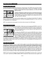
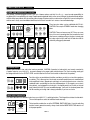
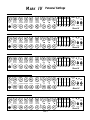
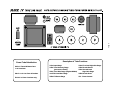
MESA BOOGIE
MARK IV
Owner’s Manual
The Spirit of Art in Technology
1317 Ross Street Petaluma, CA 94954
USA
Hello from the Tone Farm...
YOU, the smart player and all around intuitive human, have put your trust in us to
be your amplifier company. This is something we do not take lightly. Our reward is
that we’ve made a classic amplifier and by choosing this amplifier, you have become
part of the MESA family...Welcome! Our goal is to never let you down. Your reward
is that you are now the owner of an archetypical guitar amp bred of fine all tube amp
heritage...benefiting from the many patented pioneering MESA/Boogie circuits that
led to the refinement of your new instrument. Feel confident, as we do, this amp will
inspire many hours of musical satisfaction and lasting enjoyment. It was built with
you in mind, by players who know the value of a fine musical instrument and the
commitment it takes to make great music. The same commitment to quality, value
and support we make to you...our new friend.
MARK IV
Table of Contents
PRECAUTIONS
REAR PANEL:
OVERVIEW _____________________________ 1
A.C. RECEPTACLE _______________________ 9
FRONT PANEL:
FUSE __________________________________ 9
POWER-UP ____________________________ 2
REVERB & REVERB FOOTSWITCH ________ 10
CONTROLS:
EQ ROCKER SWITCH ____________________ 10
RHYTHM 1 GAIN ________________________ 3
SATELLITE CONTROL: EQ & SEND JACK __ 10
PULL BRIGHT __________________________ 3
EFFECTS LOOP SECTION ____________ 10 & 11
R 1 TREBLE ____________________________ 3
RECORDING OUT _______________________ 11
R 1 + R 2 BASS and R 1 + R 2 MID _________ 3
SLAVE OUT (D.I.) ________________________ 11
R 1 PRESENCE _________________________ 4
TRIODE & PENTODE SWITCH _____________ 11
R 1 MASTER ___________________________ 3
SIMUL-CLASS & CLASS A SWITCH ________ 12
RHYTHM 2 GAIN & FAT __________________ 4
HARMONICS & MID GAIN SWITCH _________ 12
R 1 + R 2 BASS and R1 + R 2 MID __________ 4
POWER TUBE SUBSTITUTION ________ 12 & 13
R 2 TREBLE ____________________________ 5
SPEAKER JACKS _______________________ 13
R 2 PRESENCE _________________________ 5
MODE SELECTOR SWITCH _______________ 13
R 2 MASTER ___________________________ 5
EXTERNAL SWITCHING JACK ____________ 14
SETTING THE LEAD MODE:
GOING STEREO ________________________ 14
LEAD GAIN _________________________ 5 & 6
FACTORY SAMPLE SETTINGS ____________ 15
LEAD TREBLE __________________________ 6
PERSONAL SETTINGS PAGE _____________ 16
LEAD BASS & LEAD MID _________________ 6
TUBE TASK CHART _____________________ 17
LEAD DRIVE ___________________________ 6
TUBE NOISE & MICROPHONICS ___________ 18
LEAD BRIGHT __________________________ 7
DIAGNOSING PRE-AMP TUBES PROBLEMS _ 19
LEAD PRESENCE & LEAD MASTER ________ 7
BIAS ADJUSTMENT ______________ 20,21 & 22
GRAPHIC EQ ________________________ 7 & 8
PARTS SHEET __________________________ 23
OUTPUT LEVEL _________________________ 8
SILENT RECORDING (Pull Switch) _________ 8
STANDBY ______________________________ 8
POWER (Full & Tweed Power) _____________ 8
NOTE: Do to the sophistication and advanced
layout of this amplifier, we strongly urge you to
read and understand the workings and how to's
of your new MARK IV...doing so will save time
and increase your enjoyment.
Your MESA/Boogie Amplifier is a professional instrument. Please treat it with respect and operate it properly.
USE COMMON SENSE AND ALWAYS OBSERVE THESE PRECAUTIONS:
Do not expose amplifier to moisture, rain or water, direct sunlight or
extremely high temperatures.
Always insure that amplifier is properly grounded.
Always unplug AC power cord before changing fuse or any tubes.
When replacing fuse, use only same type and rating.
Avoid direct contact with heated tubes.
Insure adequate air circulation behind amplifier.
Keep amplifier away from children.
Be sure to connect to an AC power supply that meets the power supply
specifications listed on the rear of the unit.
If there is any danger of lightning occurring nearby, remove the power
plug from the wall socket in advance.
To avoid damaging your speakers and other playback equipment, turn off
the power of all related equipment before
making the connections.
Do not use excessive force in handling control buttons, switches and
controls.
Remove the power plug from the AC mains socket if the unit is to be
stored for an extended period of time.
Do not use solvents such as benzene or paint thinner to clean the unit.
Wipe off the exterior with soft cloth.
Be sure to have the warranty card for this product filled out by the store at
which it was purchased and return to MESA Engineering.
YOUR AMPLIFIER IS LOUD! EXPOSURE TO HIGH SOUND VOLUMES MAY CAUSE
PERMANET HEARING DAMAGE!
No user serviceable parts inside. Refer service to qualified personnel.
Always unplug AC power before removing chassis.
EXPORT MODELS: Always insure that unit is wired for proper voltage.
Make certain grounding conforms with local standards.
READ AND FOLLOW INSTRUCTIONS OF PROPER USAGE.
MARK
MARK IV
Operating Instructions
Overview:
Congratulations for choosing the MARK IV as your new musical voice. You have purchased a handbuilt instrument of the finest
quality and craftsmanship. In 1984 Mesa/Boogie introduced the world’s first “Tri-Modal amplifier - the MARK lll - with separate
modes for Clean Rhythm, Crunch Rhythm and Lead Overdrive. Now the MARK IV concentrates six years of intervening design
experience into a masterful new instrument which promises years of musical enjoyment.
Every possible useful feature is included, some for the first time ever. Precise, separate adjustment of each mode is simplified by the
complete and logical array of controls...making the MARK IV easier to use than its predecessor. No compromises were tolerated in
regard to performance, reliability or component quality. Individual master-craftsmanship is evident throughout the construction and
testing of each MARK IV. And best of all, the sound quality of each mode is devastatingly accurate! We want your new MARK IV
to be the last amplifier you ever need to buy.
FRONT VIEW: MARK IV
Instant Gratification Demo Settings
65
65
PULL SHIFT
8 76
8 76
PULL SHIFT
PRESENCE
CONTROLS
65
65
8 76
PULL BRIGHT
MASTERS
65
9 8 76
010
54
0 10
21
9 87
0
PULL FAT
010
0
65
21
98
10
10 9
3 21
987
987
98
10
432
987
321
PULL FAT
432
OUTPUT LEVEL
80
240
750
2200
6600
LOOP
ON
32
987
321
321
10 9
54 3
1 010
54
010
10 9
LD
EQ
FULL
POWER
1 0 10
4
R2
1 010
321
21
0
INSTRUMENT
98 7
98
10
SILENT
RECORDING
(PULL)
2
1 0 10
43
R1
210
PULL FAT OUT
543
210
010 9
76 5
543
210
432
R2 TREBLE
LEAD DRIVE
43
76 5
R1+R2 MID
LEAD MID
8 76
R1+R2 BASS
LEAD BASS
9 87
654
9 87
1 010
R1 TREBLE
LEAD TREBLE
43
654
987
432
654
RHY2 GAIN
LEAD GAIN
RHY1 GAIN
INPUT
54
1 0 10
8 76
43
010 9
3 21
76 5
PULL BRIGHT
PULL FAT OUT
STANDBY
TWEED
POWER
MARK IV
PULL BRIGHT OUT
(STEREO)
(MONO)
SIG.
PATH
FX SEND
RETURN
RETURN
43
HARMONICS
CLASS A
CLASS A/ SIMUL FX LOOP
RHY 2
LEAD VOICING
POWER AMP
65
ON / OFF AUTO R2
SATELLITE SEND
REMOTE
LEVEL
SIMUL-CLASS
RHY 1
MID GAIN
2
EX SW
EXTERNAL SWITCHING JACKS
MODE SELECT
8 OHM
PAGE 1
EQ
LEAD
FT SW
OUT
SPEAKERS
RIGHT
65
SATELLITE EQ
LEAD
RHY 2
AUTO ASSIGN SWITCHES
LEFT
SLAVE (D.I.)
SATELLITE
FX LOOP
SWITCHING
TRIODE
PENTODE
98 7
98 7
OFF
43 2
1 0 10
GRAPHIC EQ
AUTO
RHY 2
98 7
117 VOLTS
60 HZ
4 AMPS
AUTO
RHY 1
1 0 10
3A SB
FX LOOP ON
FULL TIME
1 0 10
FUSE
REVERB
REVERB FTSW.
432
RECORDING
65
REAR VIEW: MARK IV
4 OHM
4 OHM
HANDBUILT IN PETALUMA CALIFORNIA
RHYTHM 1
RHYTHM 2
LEAD
FRONT PANEL:
First familiarize yourself with the layout of the Front Panel and plug in the FU-3 footswitch which is located on the underside of the
chassis towards the middle and about mid way forward of the Rear Panel. It’s not necessary to unplug the footswitch after use, simply
use the handy fasteners on the left and right side of the cabinet and attach the unit for storage and/or transport. Make sure the
footswitch cable is connected properly. It has three pins and a key way for mating itself to the female portion of the jack. When
connected, the FU-3 footswitch will allow you to select the various modes,FX Loop and the EQ of the MARK IV remotely. If you don’t
have the footswitch available, the MODE SELECT rotary switch located on the Rear Panel will access the modes. Before we get too
specific about each control, let’s audition the 3 modes with some basic settings just to get your new MK IV up and purring.
POWER-UP:
Connect your favorite guitar to the instrument input jack. Flip the power switch to the FULL POWER position while leaving the
STANDBY switch set to “STANDBY.” ( It is always a good idea to practice this start up procedure as at least 30 seconds of warm-up
time lessens the shock on cold power tubes, thus prolonging their life substantially.) Using the example below as a guide, set the
controls as illustrated and flip the STANDBY switch to the “ON” position. Listen to the three distinctly different modes using either the
footswitch or the MODE SELECT rotary switch as mentioned in the previous paragraph.
65
2
65
2
65
65
8 76
PULL BRIGHT
MASTERS
PULL SHIFT
8 76
PULL SHIFT
8 76
PRESENCE
CONTROLS
0 10
PULL FAT
321
9 8 76
0 10
321
PULL BRIGHT
54
10 9
98
10
0 10
9 8 76
0 10
8 76
98
10
0
54
0 10
21
0 10
9 8 76
10 9
8 76
PULL FAT
98 7
321
21
INSTRUMENT
43
98 7
2
LOOP
ON
43
98 7
321
Pull BRIGHT out
43
EQ
OUTPUT LEVEL
80
240
750
2200
6600
FULL
POWER
1 0 10
Pull FAT out
SILENT
RECORDING
(PULL)
2
1 0 10
LEAD DRIVE
43
1 0 10
43
LEAD GAIN
543
Pull
LD
1 0 10
76 5
R2
R1
210
54
543
210
654
R2 TREBLE
LEAD DRIVE
543
210
987
R1+R2 MID
LEAD MID
32 1
210
32 1
654
543
54
987
654
32 1
R1 TREBLE R1+R2 BASS
LEAD TREBLE LEAD BASS
RHY2 GAIN
LEAD GAIN
987
54
0 10 9
0
INPUT
8 76
43
RHY1 GAIN
0 10 9
32 1
76 5
Pull Shifts for
R2, Lead Out
10 9
FAT out
10 9
RHY 2 pull
BRIGHT out
98 7
RHY 1 pull
STANDBY
TWEED
POWER
MARK IV
In the example above the Graphic E.Q. is set in the ever so popular “V” curve shape. Most players tend to use it more in the LEAD
channel, finding the RHYTHM channel plenty sweet by itself without the use of the E.Q. ( for more information regarding the E.Q., see
page 6 .)
(STEREO)
(MONO)
SIG.
PATH
FX SEND
RETURN
RETURN
43
HARMONICS
CLASS A
CLASS A/ SIMUL FX LOOP
RHY 2
LEAD VOICING
POWER AMP
65
ON / OFF AUTO R2
SATELLITE SEND
REMOTE
LEVEL
SIMUL-CLASS
RHY 1
MID GAIN
2
EQ
LEAD
EX SW
FT SW
EXTERNAL SWITCHING JACKS
OUT
SPEAKERS
RIGHT
65
SATELLITE EQ
LEAD
RHY 2
AUTO ASSIGN SWITCHES
LEFT
SLAVE (D.I.)
SATELLITE
FX LOOP
SWITCHING
TRIODE
PENTODE
98 7
98 7
OFF
43 2
1 0 10
GRAPHIC EQ
AUTO
RHY 2
98 7
117 VOLTS
60 HZ
4 AMPS
AUTO
RHY 1
1 0 10
3A SB
FX LOOP ON
FULL TIME
1 0 10
FUSE
REVERB
REVERB FTSW.
432
RECORDING
65
And now looking to the Rear Panel...
MODE SELECT
8 OHM
4 OHM
4 OHM
HANDBUILT IN PETALUMA CALIFORNIA
RHYTHM 1
RHYTHM 2
LEAD
Viewing from the back of the amp, locate the REVERB control and set to 3. Set E.Q. switch to the center position (OFF). LEAD
VOICING switch should be set to HARMONICS and ignore the FX Loop for now. Set the power amp switches to SIMUL-CLASS and
TRIODE.
After these initial settings have been made, plug in your guitar (STANDBY switch “ON’) and play! Use the three MASTER controls to
balance volumes between the modes. Use the OUTPUT LEVEL to raise or lower overall playing loudness. Dial in the PRESENCE
controls to set brightness before adjusting TREBLE controls. RHYTHM 1 should be clean, fat, warm and round. RHYTHM 2 should be
near maximum crunch, yet it’s capable of many other sounds as well. The LEAD mode should have searing sustain even though its
GAIN control is only around half. Now lets get into understanding the controls and the way they interact to obtain the sounds you want
to hear.
PAGE 2
CONTROLS:
RHYTHM 1 GAIN:
PULL BRIGHT
43
98
10
Setting the RHYTHM 1 mode adjusts the input sensitivity for the clean RHYTHM mode. With most guitars, this mode stays clean until
around 8 where it begins to overdrive. Use the R1 MASTER to control loudness if you want slight overdrive at low volumes. This mode
was very carefully designed to provide great rhythm sounds, from the best of vintage, Fender-type (clean or solo)
to a more modern, shimmering “funk rhythm” sound. Be sure to try this mode played really loud; you’ll love it for
76 5
blues or rock. (See the “Traditional Blues” setting on the Sample Settings sheet found on page 15 of this manual.)
21
0
INPUT
INSTRUMENT
RHY1 GAIN
PULL BRIGHT:
PULL BRIGHT
43
98
10
This function adds shimmer and sparkle to your sound when activated. Note that the amount of added brightness varies with the R1
GAIN setting: more brights at lower settings, less at higher. For super shimmer, run the GAIN at around 3 or 4
with the BRIGHT pulled out. For the most naturally balanced sound, run the GAIN at around 6 or 7 with the
76 5
BRIGHT pulled.
21
0
RHY1 GAIN
RHYTHM 1 TREBLE:
9 87
PULL FAT
321
PULL BRIGHT
54
98
10
0 10
RHY2 GAIN
3 21
43
21
0
RHY1 GAIN
8 76
This control dials in the MARK IV’S predominate tonal characteristic. In the 0 to 3 range, a dark, warm jazz tone is obtainable.
Most common settings are in the 5 thru 7 range and note how the overall “gain” of the mode increases with higher TREBLE
control settings. This is because so much of the energy of the musical spectrum is channeled
through this most powerful tone control. As this is true for all modes, the MARK IV includes three
76 5
65 4
0 109
separate TREBLE controls.
R1 TREBLE
R1 + R2 BASS & R1 + R2 MID:
These are the only shared tone controls aboard the MARK IV. Because of internal circuitry changes which occur when switching
modes, you will most likely find R1’s optimum setting works well for RHYTHM 2. The effect of these two tone controls is largely
determined by the setting of the TREBLE controls. Only when the TREBLE control is set very low (or off) are the BASS and MID
controls really strong.
9 87
9 87
21
98
10
0 10
R1+ R2 BASS
65 4
3 21
3 21
43
0
R1TREBLE
65 4
0 10
76 5
R1+ R2 MID
At normal TREBLE control settings, their effect is greatly diminished and they serve mainly to round
out and fill up the overall tone. Do note however, that setting the BASS control too high can result
in unwanted flubbiness, especially in RHYTHM 2. The recommended setting for the BASS control
is 0 to 3 and for the MID control it is 4 to 7 .
PAGE 3
CONTROLS: (Continued)
9 87
PRESENCE
CONTROLS
87 6
54
321
65 4
3 21
0 10 9
0 10
76
PULL SHIFT
R1 PRESENCE:
This control adjusts frequencies higher than those found on the TREBLE control. There are so many different sounds that RHYTHM
1 can produce, you must experiment using your guitar and your ears. Try settings such as low on the TREBLE control, high on the
PRESENCE control...and the opposite...as an experiment, both with and without the BRIGHT switch.
3
54
R2 TREBLE
2
R2 MID
Notice too that when playing very loud, higher settings of the PRESENCE will help you cut through
the background wash of cymbals. Don’t forget to turn RHYTHM 1 up loud and blow...It’s a great
overdrive sound as well !
R1 MASTER:
76
32
76
32
This MASTER control adjusts the signal level of the RHYTHM 1 mode. It allows you to run various settings of the RHYTHM 1 GAIN
while still controlling overall RHYTHM 1 volume via the MASTER. That’s important because of the striking
tonal differences the BRIGHT switch makes at lower and higher settings of gain, and because high GAIN
R2 TREBLE
R1
control settings are useful for producing “onset of clip” distortion sounds. The R1 MASTER also acts as an
LEAD DRIVE
Effects Send Level control for RHYTHM 1.
65 4
0 10 9
54
9 87
0 10
PRESENCE
MASTERS
54
321
3 21
87 6
54
RHYTHM 2 GAIN & FAT:
PULL FAT has tremendous impact on both the gain and voice of RHYTHM 2. When pushed in, RHYTHM
2 loses gain in the low mids and the sound reveals more of your guitar’s inherent personality. For clean
playing or blues styles you’ll probably prefer the FAT pushed in. Work with the R2 TREBLE control and
PRESENCE controls to dial in traditional blues-style solo tones from RHYTHM 2. For hard rock and
metal sounds, pull out the FAT and max the RHYTHM 2 GAIN control, using RHYTHM 2 TREBLE and
PRESENCE to dial in cut and brightness.
PULL FAT
98
21
10
98
10
0
0
RHY2 GAIN
INSTRUMENT
INPUT
43
43
RHY1 GAIN
76 5
21
76 5
PULL BRIGHT
RHYTHM 2 GAIN sets the overall characteristic of this mode, which is the most versatile of the three modes. At high settings 9
10
and with the FAT switch pulled, RHYTHM 2 produces its maximum gain for crunch and can double as an alternate lead sound. This
modes’ gain falls off quickly as the control’s knob is reduced, providing a range of lower-gain “onset of clip” sounds and the ability to
produce an alternate voicing for clean sounds at its lowest settings.
R1 + R2 BASS & R1 + R2 MID:
These are the only shared tone controls on the MARK IV. You probably won’t need much adjustment from their RHYTHM 1 setting
because they are designed especially to have less dramatic effect in RHYTHM 2. Again you’ll notice
that the strength of these controls is influenced by how high or low the RHYTHM 2 TREBLE is set.
9 87
9 87
98
10
0 10
R1+ R2 BASS
6
54
0 10
54
3 21
43
21
0
R1 TREBLE
6
3 21
76 5
R1+R2 MID
Excessive settings (especially of the BASS control) can cause a flubby sounding distortion if the
TREBLE control is set low.
PAGE 4
CONTROLS: (Continued)
9 8
9 87
98
21
10
21
0 10
0
0
10
43
43
R2 TREBLE
R1 +R2 MID
R1 +R2 BASS
3 21
RHYTHM 2 TREBLE:
This control along with RHYTHM 2’s PRESENCE control should be worked with together to produce the desired gain and brightness
of the mode. Setting the TREBLE higher, as always, increases the gain of the mode and allows increased distortion and sustain.
Lower settings allow the MID and BASS controls to become more dominant adding warmth to the
6
5
4
5
6
sound.
5
7
7
6
R2 PRESENCE:
987
PULL SHIFT
9 8
0
10
21
PRESENCE
CONTROLS
0 10
43
43
3 21
RHYTHM 2’s PRESENCE control also works on higher frequencies than the TREBLE, so by working with both controls, you can
produce any sound from fat and thick to searing and shredding. Don’t be surprised if loud group playing requires higher PRESENCE
control settings to cut through...this is why we’ve provided the three modes with their separate Presence
controls.
6 5
76 5
654
21
0
The RHYTHM 2 (and LEAD) PRESENCE control also has a PULL SHIFT feature. This Shift normalizes
the amount of high frequencies produced in the power section. With the PULL SHIFTS engaged, the
Presence controls will be more effective and will act on a higher frequency range. When the SHIFTS are pushed in, a punchier, more
aggressive tone is produced and the PRESENCE controls effectiveness is reduced.
R1
TREBLE
R2
9
10
PULL
9
10
PRES
CONT
0
9 8 76
98
10
21
0
PULL BRIGHT
MASTERS
54
0 10
21
10
21
0
21
98
0
76 5
43
43
10
21
R2
R1
321
76 5
3
R2 TREBLE
LEAD DRIVE
3
3
9
R2 MASTER:
This MASTER control is used to balance playing loudness in RHYTHM 2 and also determines the amount of RHYTHM 2 signal at the
Effects Send jack.
0
SETTING THE LEAD MODE:
0
54
3
0 10 9
87 6
21
INSTRUMENT
RHY2 GAIN
LEAD GAIN
INPUT
PULL FAT
21
RHY1 GAIN
PULL FAT
98
10
0
PULL BRIGHT
43
10
76 5
21
76 5
43
98
LEAD GAIN:
This control sets up the input sensitivity for the LEAD mode. The more signal strength dialed in here, early in the preamp, the more
distortion will be available at the LEAD DRIVE control. Yet it is not necessary or recommended to turn the LEAD GAIN fully up.
Best results will occur with settings in the 8 range. As you approach a Gain of 7 the Lead sound will
become extremely focused, rich and smooth; above 8 , total saturation occurs, reducing the effectiveness
of the tone controls and causing increased “microphonics” and noise in the preamp tubes. You’ll notice
subtle shifts in distortion tonality by trying different mixes of LEAD GAIN and LEAD DRIVE. The LEAD
GAIN control incorporates a PULL FAT for thickening the sound and saturating the signal further. This pull
shift lowers the frequency of the Treble, adding a boost in the lower midrange. Try this shift for beefing up
the sound of weaker, stock pick-ups or simply for adding focus at virtually any setting of the GAIN control.
PAGE 5
CONTROLS: (Continued)
LEAD GAIN: (Continued)
There are also some great singing, slightly distorted sounds that come from low settings of Gain and Drive with FAT pushed in. “Onset
of Clip” and “threshold of distortion” are phrases often used to describe these sounds, which reveal the true blue beauty of the MARK
IV’s all-tube lineage (see the traditional blues setting on the Sample Settings sheet further back in this manual).
LEAD TREBLE:
98
PULL FAT
10
9 8 76
98
10
PULL BRIGHT
0
21
98
PULL FAT
0 10
21
10
54
321
43
21
0
INSTRUMENT
0
10
43
43
76 5
76 5
R1 TREBLE
LEAD TREBLE
RHY2 GAIN
LEAD GAIN
0
RHY1 GAIN
INPUT
76 5
21
76 5
43
98
This control along with RHYTHM 2’s PRESENCE control should be worked with together to produce the desired gain and brightness
of the mode. Setting the TREBLE higher, as always, increases the gain of the mode and allows increased distortion and sustain.
Lower settings allow the MID and BASS controls to become more dominant adding warmth to the
sound.
98
10
9 8 76
98
98
PULL FAT
10
9 8 76
1
0
21
10
98
10
098
21
PULL FAT
0 10
0
0
21
98
54
0 10
21
10
0
PULL BRIGHT
21
43
43
0
INSTRUMENT
0
21
10
21
54
R1+R2 BASS
LEAD MID
321
76 5
R1+R2 BASS
LEAD BASS
7
43
R1 TREBLE
LEAD TREBLE
7
321
76 5
76 5
43
43
RHY2 GAIN
LEAD GAIN
0
RHY1 GAIN
INPUT
7
43
76
43
98
LEAD BASS & LEAD MID:
Both of these controls add body and warmth without really affecting the strength of the signal. Merely dial in to your liking but note
again that too much Bass combined with too high of a LEAD GAIN setting will
take away from the tight, highly focused lead sound that this mode offers.
6 5
6 5
5
6 5
98
10
9 8 76
98
98
PULL FAT
10
9 8 76
1
0
10
98
10
098
21
21
0
21
98
0
PULL FAT
0 10
21
PULL BRIGHT
0
10
54
0 10
21
43
43
0
INSTRUMENT
0
21
10
21
54
R1+R2 BASS
LEAD MID
321
76 5
R1+R2 BASS
LEAD BASS
76 5
43
R1 TREBLE
LEAD TREBLE
76 5
321
76 5
76 5
43
43
RHY2 GAIN
LEAD GAIN
0
RHY1 GAIN
INPUT
76 5
43
76 5
43
98
LEAD DRIVE:
This control works in conjunction with LEAD GAIN to determine the amount of sustain and overdrive. It is not necessary or even
recommended to run the LEAD DRIVE way up in order to generate a sound that is fully saturated, so try settings in the 5 to 7
region. Higher settings tend to increase noise and squealing without really embellishing the sound or feel.
Notice that this control comes on very rapidly at low settings, then changes only
gradually throughout the rest of its rotation. Familiarize yourself with the point
which represents the beginning or “threshold” of overdrive; it creates an expressive distortion which is touch-sensitive to picking dynamics, providing harmonics that stay glued to the fundamental note. You’ll find lots of great sounds
in this 2 to 4 region!
PAGE 6
CONTROLS: (Continued)
98
0
PRESENCE
CONTROLS
10
98
10
21
21
PULL BRIGHT
MASTERS
0
10
21
43
32 1
0
9 8 76
43
43
98
LEAD BRIGHT:
The importance of this switch is a must to understand. At low to medium playing volumes, the LEAD BRIGHT adds desirable sizzle,
and gain in the highs to the overdrive sound and contributes to a “big easy feeling” as well. At high volumes the LEAD BRIGHT can
cause real problems, such as excess squealing and noise. At high volumes it is often not necessary to supplement the LEAD mode’s natural gain because the power amplifier will also be going into overdrive. So please
76 5
76 5
keep in mind how your Boogie’s cascading gain works: there are several amplifier stages in a row with “gain”
controls
at all the crucial points in between, so you can produce enormous amounts of amplifier gain at low
R2 TREBLE
R1
LEAD DRIVE
volumes. Your MARK IV is capable of playing very loud as well, but it is not feasible to play with high gain
54
and high volume simultaneously without causing squealing, feedback and excess noise. A Ferrari is a great
76 5
car in tight corners and it is wickedly fast on the straightaway, but at some combination of speed and cornering
it will spin-out. So will your MARK IV !
0 10
So remember to balance “gain” with “volume”. In the LEAD mode, a general guideline might be push in the BRIGHT for loud playing
and pull out the BRIGHT at lower volumes. Your 12AX7 tubes will be much happier...and so will your soundman! (Another switch
similarly “dangerous” at high gain/high volume settings is the Rear Panel LEAD VOICING switch, described later in this manual.)
9 8 76
PRESENCE
CONTROLS
PULL BRIGHT
MASTERS
21
98
9 8 76
10
0
10
54
321
43
You may find that pulling out the PRESENCE control gives you a better balance when playing with a band,
while pushing in the PRESENCE control provides a bigger and fatter sound for mic’ed up recording. When
the shift is pushed in and the graphic EQ is set to the “Classic V” setting (see below), unholy amounts of tight,
chunking bottom end are available. Give this setting a try for metal rhythm grooves.
R1
0 10
21
76 5
0 10
R2 TREBLE
LEAD DRIVE
321
43
98
LEAD PRESENCE & LEAD MASTER:
These two controls work similarly to the ones previously discussed. Note that adding lots of PRESENCE (which is extra gain in the
highest frequency range) to high gain and high volume settings may aggravate the spin-out of squealing and excess noise. The LEAD
PRESENCE control has a PULL SHIFT which operates just like the R2 PRESENCE PULL SHIFT - it reduces
the amount of low frequencies and shifts the range of the Presence effect.
54
76 5
0
GRAPHIC EQ:
This feature can be switched IN or OUT via the footswitch or the mini-rocker switch located on the Rear Panel. The rear rocker switch
has three positions: left is EQ IN (all modes), center position is EQ OUT (all modes) and right position is EQ AUTO RHY 2, which
means the EQ comes on automatically whenever RHYTHM 2 is selected.
76 5
0
80
240
750
2200
6600
21
10
43
98
SILENT
RECORDING
(PULL)
OUTPUT LEVEL
Note that once the EQ is switched IN via the rocker switch, the footswitch will not be able to
take it back out. Indicator LED’s on both the footswitch and the amplifier’s Front Panel indicate
EQ status. Setting up the EQ is strictly a matter of personal taste and enjoyment, so prepare to
have some fun dialing in fine nuances of tonal shading - or going for the outer extremes of
weirdness! The one setting we recommend you use as a departure point is one we call the
“classic V”. It involves boosting the lowest and highest frequency sliders the most, boosting the
240 and 2200 sliders somewhat less and cutting the 750 center band.
You can be as subtle or extreme as you want with this pattern; and when you’re going for extremes, you’ll notice that the 750 slider is
the one that’s by far the most crucial. Once you’ve boosted the other four bands, you’ll find that by adjusting only the 750, y ou can
determine the strength of the entire EQ effect. You’ll also notice that there is a certain point where the sound goes from “max imum
thrash” to thin and buzzy. You’ll find that your ears quickly become adjusted (addicted?) to this “hyper-tone and when you switch the
PAGE 7
CONTROLS: (Continued)
GRAPHIC EQ: (Continued)
EQ back out of the circuit, the straight tone sounds to flat. Don’t worry! It’s just “hearing hangover”. All the MARK IV’s modes were
developed without using the EQ so that it could be an accessory - not a necessity.
OUTPUT LEVEL:
This control adjusts the playing loudness of all three modes equally. Once you’ve got the sounds set up as you would like them, using
this one control will allow you to work louder or softer venues. Notice that the OUTPUT LEVEL
SILENT
control also functions as an Effects Return control, owing to its location in the signal chain.
RECORDING
(PULL)
6 5
1 0 10
2
4 3
987
80
240
750
2200
6600
OUTPUT LEVEL
54
3 21
8 76
SILENT RECORDING: (Pull Switch)
This push/pull switch turns off the signal at the output stage therefore muting the speaker. This enables you to record silentl y (using
the RECORDING out jack, not the SLAVE D.I.) without the need to disconnect the speaker.
SILENT
Signal strength to the recording circuit is still regulated by the OUTPUT LEVEL control, even
RECORDING
(PULL)
though the speaker cannot be heard.
0 10 9
80
240
750
2200
6600
OUTPUT LEVEL
NOTE: Remember...a load must be maintained on the amplifier to avoid damage to the
transformer. A soak resistor (8 ohms) can be purchased for just such purposes. See your
local dealer or give us a call and we’ll assist you if need be.
STANDBY:
The STANDBY switch turns off the high voltages inside the amplifier while allowing the tube filaments to stay warm and ready fo r
immediate use. It’s a good practice to turn on the A.C. power with this switch in the
SILENT
EQ
STANDBY position, allowing the tubes 30 seconds or so to warm up. This procedure
RECORDING
(PULL)
prevents tube problems and increases their toneful life substantially.
ON
987
43 2
1 0 10
6 5
OUTPUT LEVEL
80
240
750
2200
6600
The STANDBY switch is also the perfect feature for set breaks as well.
STANDBY
MARK IV
NOTE: Remember...remove the protective plastic coating from the tubes before you
connect the MARK IV to an A.C. outlet.
POWER: (Full & Tweed Power)
This switch has three positions: FULL POWER, OFF and TWEED POWER. The OFF position is in the center and is unlabeled. Use
FULL POWER for maximum volume and clean headroom. TWEED POWER works like a built-in variac, reducing all the internal
voltages for a spongy, vintage feeling and an extraordinary “brown sound”.
SILENT
RECORDING
(PULL)
EQ
ON
FULL
POWER
987
43 2
1 0 10
LOOP
6 5
OUTPUT LEVEL STANDBY
MARK IV
TWEED
POWER
POWER is reduced somewhat too, making it easier to achieve a big overdriven power sound, especially when TWEED POWER is used in conjunction with Class A power (this will be explained later in
this manual). Another virtue of TWEED POWER is that the lowered voltages will greatly extend tube
life and overall reliability, while still producing enough power to work many of your gigs...and all of your
recording sessions!
PAGE 8
REST AREA
REAR PANEL MKIV
(MONO)
SIG.
PATH
FX SEND
SATELLITE SEND
RETURN
RETURN
HARMONICS
CLASS A
CLASS A/ SIMUL FX LOOP
RHY 2
LEAD VOICING
POWER AMP
43 2
RECORDING
SIMUL-CLASS
RHY 1
MID GAIN
1 0 10
EQ
LEAD
EX SW
FT SW
EXTERNAL SWITCHING JACKS
OUT
SPEAKERS
(STEREO)
LEVEL
43 2
SATELLITE
RIGHT
SLAVE (D.I.)
43 2
GRAPHIC EQ
REMOTE
LEFT
TRIODE
PENTODE
987
ON OFFAUTO R2
SATELLITE EQ
LEAD
RHY 2
AUTO ASSIGN SWITCHES
1 0 10
65
65
REVERB
AUTO
RHY 2
987
FX LOOP
SWITCHING
3A SB
117 VOLTS
60 HZ
4 AMPS
AUTO
RHY 1
987
FUSE
FX LOOP ON
FULL TIME
65
REV FTSW.
1 0 10
MODE SELECT
8 OHM
4 OHM
4 OHM
HANDBUILT IN PETALUMA CALIFORNIA
RHYTHM 1
RHYTHM 2
LEAD
A.C. RECEPTACLE:
The MARK IV uses a removable I.E.C. type power cord to supply the A.C. power. The power cord supplied with your unit should
be used whenever possible as we chose it for its snug fit. Because this type of RECEPTACLE is somewhat universal and used in
many products both in and out of electronic musical instrument domain, you may use other cords of this
type when the one supplied is not available. Should this become necessary, check that the cord is seated all
the way into the RECEPTACLE to insure an uninterrupted performance. In the U.S., the proper voltage is
117 volts A.C. (110-120). Always be sure to connect the MARK IV to its rated voltage to avoid damaging
3A SB
internal circuitry.
117 VOLTS
FUSE
60 HZ
4 AMPS
FUSE:
The FUSE should be a 3 amp Slo-Blo for use with 100 or 117 volt A.C. Mains. Should the FUSE blow, replace it with a similar type and
rating, then watch the power tubes as you start the amp back up again.
FUSE
3A SB
117 VOLTS
60 HZ
4 AMPS
Warm up the tubes first with the amplifier in STANDBY mode, then, watching them carefully, flip the STANDBY
switch to ON. If you see a tube arc or spark inside, that is definitely the problem and can be remedied by an
easy power tube replacement. In many cases though, the bad tube will only fail intermittently. Watch for a
while and if any tubes start to run red-hot, this is the cause of your original problem.
If everything appears OK, tap on each power tube to reveal the faulty one, because a blown fuse is nearly
always caused by a bad power tube (s). Running the amp in TWEED power will very likely offer a temporary
remedy and let you get through the gig. If the FUSE blows immediately when switching on the A.C. power (in
the STANDBY mode), then some other problem is the cause, most likely a failed rectifier diode. (See the section on tube maintenance
further back in this manual for more assistance and helpful hints on how to maintain the life of the power tubes).
PAGE 9
REAR VIEW MKIV
(Continued)
76
8
GRAPHIC EQ
SATELLITE
10 9
REVERB
210
REVERB & REVERB FOOTSWITCH:
REVERB is a simple depth control which activates the rich all-tube, three-spring analog circuitry. Even though many players have
more modern digital reverbs and delays, there is still something quite pleasant about this natural-sounding,
REV FTSW.
traditional Reverb system that we think you’ll enjoy. The REVERB effect may seem more intense in some
3
54
modes (such as RHYTHM 1) than in other modes, because each mode has a slightly different EQ characteristic and attack dynamic. This represents normal REVERB operation and is no cause for concern.
SIG.
ON OFF AUTO R2
REMOTE
The 1/4" jack on the Rear Panel labeled REV FTSW. (as shown in the illustration) allows you control of the
REVERB remotely when the (optional) Mesa/Boogie REVERB footswitch is connected. See your nearest
Boogie Pro Center for this item or call us directly we’ll be happy to assist you.
SATELLITE EQ
PATH
SATELLITE SEND
EQ ROCKER SWITCH:
This feature was explained earlier in the Graphic EQ section of this manual. Refer back to it if you need help understanding what the
function of this switch is.
8 76
SATELLITE
GRAPHIC EQ
117 VOLTS
60 HZ
4 AMPS
3
10 9
3A SB
54
210
REVERB
REV FTSW.
FUSE
ON OFF AUTO R2
REMOTE
SATELLITE EQ
SIG.
PATH
SATELLITE SEND
8 76
REVERB
4 AMPS
SATELLITE
GRAPHIC EQ
10 9
FUSE
210
SATELLITE CONTROL: EQ & Send Jack
Mesa/Boogie offers two different Satellite companion amplifers that enable you to either reinforce your already amazing tone, or split
and process the signal using the Effects Loop. A simple 60 watt version called the Satellite Sixty, as well as a 75 watt Simul-Class with
Graphic EQ make up this supportive duo with the Simul-Satellite being the obvious
choice for most MARK IV owners. In the popular stereo scheme, a processors’ OutREV FTSW.
3
puts feed the two Returns ( Left and Right ) on the MARK IV’S Rear Panel and the
54
Left Return is then sent on to the matching Satellites’ Input via the Satellite Send jack.
3A SB
This buffered line may then travel across the stage with little or no tonal degradation
117 VOLTS
due to cable length or impedance mismatching.
SATELLITE EQ
50-60 HZ
ON OFF AUTO R2
SIG.
PATH
The MARK IV has the ability to control the Simul-Satellite’s Five Band EQ remotely
and automatically - tracking the auto assign function and the Footcontroller choices as
they are used aboard the MARK IV. In this way every nuance and setting of the master amp is relayed to the slave amp creating a
truly awesome spread tonally and dynamically.
REMOTE
SATELLITE SEND
EFFECTS LOOP SECTION:
This section of the MARK IV is quite sophisticated, offering two LOOPS and a selector switch. The LOOP labled NORMAL stays on
all the time. The other LOOP is switched IN or OUT of the circuit by either the footswitch, the programming rocker switches or the
external jacks (when the MARK IV is being controlled by a MIDI switcher). Notice that if the switchable
LOOP is turned on by the rockers or the external jack, the footswitch cannot turn it back off. Two rocker
switches are provided so you can pre-set the LOOP to come on in conjunction with any one or two modes.
(If an effect is desired on all three modes, use the NORMAL LOOP.) The LOOPS were designed in this way
so you can automatically have your effects in when selecting, say, RHYTHM 1 and/or RHYTHM 2, yet still
LEFT
RIGHT
FX LOOP ON
FULL TIME
FX LOOP
SWITCHING
AUTO
RHY 1
AUTO
RHY 2
LEAD
RHY 2
AUTO ASSIGN SWITCHES
(STEREO)
(MONO)
SIG.
PATH
FX SEND
RETURN
RETURN
PAGE 10
REAR VIEW MKIV
(Continued)
EFFECTS LOOP SECTION: (Continued)
be able to footswitch in the effects mid-way through a LEAD mode solo, for example. Remember that the MASTERS double as effects
send controls and the OUTPUT LEVEL also works as an Effects Return control.
AUTO
RHY 1
AUTO
RHY 2
RECORDING
43 2
FX LOOP ON
FULL TIME
65
LEAD
RHY 2
AUTO ASSIGN SWITCHES
LEFT
LEVEL
RIGHT
(STEREO)
OUT
FX SEND
3
8 76
54
210
SLAVE (D.I.)
(MONO)
10 9
FX LOOP
SWITCHING
987
RECORDING OUT:
Following the enormous success of this feature in the Quad and Studio Preamps, where they’ve been used on numerous professional
- and countless home recordings, this proven recording circuitry has been included into your new MARK IV. This recording circuit
can be used while performing live or silently at all hours of the night. Do not unplug the
speaker when you wish to record silently - merely use the SILENT RECORDING pull switch
1 0 10
(located on the amplifiers Front Panel).
RETURN
RETURN
Even though the RECORDING OUT has its own LEVEL control, the amount of signal available
is determined by the MASTERS and the OUTPUT LEVEL control. You’ll find that the RECORDING OUT does a pretty remarkable job of simulating the complex functions of power
amp, speakers and microphone while at the same time in very little need of any EQ’ing.
Notice also that the presence controls are inactive in the recording process, as they are part of the power amp section. The built-in EQ
works well for adjusting tonal nuances when recording and your mixing board’s EQ may also be helpful, though not much of either is
needed. Finally, you may use the RECORDING OUT for driving the p.a. directly. For stereo recording, connect the RECORDING OUT
to your stereo effect, then connect the left and right outputs of the effect into separate channels of the recording mixer.
LEFT
2 10
RETURN
8 76
54
3
FX SEND
RETURN
SLAVE (D.I.)
(MONO)
3
LEVEL
RIGHT
(STEREO)
8 76
LEAD
RHY 2
AUTO ASSIGN SWITCHES
54
10 9
AUTO
RHY 2
210
FX LOOP
SWITCHING
AUTO
RHY 1
10 9
FX LOOP ON
FULL TIME
RECORDING
SLAVE OUT (D.I.):
This is a traditional Boogie feature that offers an adjustable-level signal for driving external slave power amplifiers. Here the signal is
derived from the speaker terminal, so a speaker (or load resistor) must be connected at all times! The D.I. can also be used as a
feed to a p.a. but quite a lot of EQ’ing will be needed at the board. For much better results, use
the RECORDING OUT when feeding a p.a. board.
OUT
A final use for the SLAVE is to drive a string of effects. This is a complex set-up requiring
another power amp (stereo) and two, or better yet three speaker cabs. In this hook-up the
entire MARK IV functions as a tone-generating preamp, with the output taken from the
SLAVE D.I. and fed into the effects string. The output of the last effect is then used to drive a
stereo power amp - such as our 50/50 Stereo or Stereo Simul-Class Two Ninety power
amps - which in turn would power a pair of speakers.
Remember, the speaker jack of the MARK IV must be loaded by either a power-soak type resistor (which alters the tone badly)
or an actual speaker. This “middle” speaker will provide a dry or un-effected sound and is sometimes just a single 12 hidden under the
stage.
NOTE: Once signal is taken from the SLAVE D.I. Output, it cannot be inserted back into the MARK IV as a feedback loop will be
created resulting in a terrible squeal. Think of the SLAVE as a one way send.
TRIODE
SIMUL-CLASS
HARMONICS
LEAD VOICING
POWER AMP
TRIODE / PENTODE SWITCH:
This switch reconfigures the circuitry for the two outer-end power tubes. PENTODE increases power and punch, and results in a
harder clip. Use this setting for loud, live applications such as un-mic’ed blues or country gigs.
PENTODE
CLASS A
MID GAIN
TRIODE lowers the power and softens and smooths the onset of clip. This makes it easier to get a rich
singing sound full of sustain and harmonics, but some headroom is sacrificed for this sweeter response.
PAGE 11
REAR VIEW MKIV
(Continued)
SIMUL-CLASS / CLASS A SWITCH:
8 76
10 9
8 76
CLASS A
MID GAIN
OUT
3
210
54
PENTODE
SPEAKERS
LEVEL
LEAD VOICING
3
210
54
POWER AMP
This switch selects between two-tube and four-tube operation in the power section. In the CLASS A position, only the two end power
tubes are active, producing around 30 watts before clipping when operating TRIODE, or 50 watts when in PENTODE. For the nastiest
shredding tone and the greatest amount of power amp distortion, use CLASS A with TWEED
POWER and TRIODE.
TRIODE SIMUL-CLASS HARMONICS
8 OHM
4 OHM
4 OHM
In the SIMUL-CLASS position, the middle two 6L6’s switch on in parallel with the end tubes and
the total output is combined through our unique output transformer. You’ll find an increase in
low-end punch as well as overall volume as the power kicks up to around 85 watts PENTODE
or 70 watts TRIODE (power ratings based on standard U.S. music amp specs which call for 120
volt A.C. Mains and allow 5% distortion).
10 9
When you deliberately push the power section into clip, the wattage continues to rise, peaking out at about double. The MARK IV
provides an external jack for the power switching function so this feature can be programmed to operate in sync with, say, RHYTHM
2 via a MIDI switcher such as our MIDI Matrix.
NOTE: For the external jack to function properly, the mini-rocker switch must remain in the CLASS A position.
LEAD VOICING
POWER AMP
210
8 76
HARMONICS / MID GAIN SWITCH:
This switch affects the LEAD mode only. Most noticeable is the big increase in gain and sustain when MID GAIN is selected. This
added gain is focused in the mid-range “punch” region and is most noticeable when the LEAD DRIVE control is set very low - at the
“threshold of distortion” point discussed earlier. Using this low setting with the MID GAIN on
(switch in the down position) produces a punchier, fatter blues sound, especially when used
TRIODE SIMUL-CLASS HARMONICS
3
54
with Pentode and Simul-Class.
PENTODE
CLASS A
MID GAIN
10 9
As the setting of the LEAD DRIVE control is increased, the MID GAIN continues to add huge
amounts of extra boost, which at some point will become overwhelming and will cause unnec3
54
essary noise, squealing and feedback when used in conjunction with the LEAD BRIGHT and
8 OHM
4 OHM
4 OHM
LEAD FAT switches. For loud high-gain lead playing most seasoned veterans will prefer the
switch in its HARMONICS position (so named because it produces a carefully balanced harmonic spectrum rather than the blatant mid-boost sound). To duplicate the sounds of our fabled MARK II-C, switches should be set
for HARMONICS and TRIODE, with the PRESENCE controls pulled out. This produces a great balance between punch, smoothness
and rich overtones to deliver a guitar voice that’s truly classic! Notice that hiss, noise and feedback levels are extremely low for an
amplifier with this much gain.
OUT
SPEAKERS
210
8 76
LEVEL
10 9
POWER TUBE SUBSTITUTION:
This procedure is in keeping with Mesa/Boogie’s quest for ultimate versatility. As you know, different tubes offer different sounds and
playing characteristics and your new MARK IV offers four choices: FIRST: the standard four 6L6’s which produce by far the best allaround performance. They deliver the most powerful clean sounds along with the richest distortion. SECOND: Type 5881 is similar to
the 6L6, but these tubes are just slightly less powerful. Although they will produce a somewhat rounder, more “vintage” tone. THIRD:
For those seeking the traditional British edge to their overdrive sounds, EL-34’s can replace the 6L6’s in the end two sockets (outerleft and outer-right). When running the amp in class A, only the two EL-34’s will be operating. In Simul-Class, a combination of two
6L6’s plus the EL-34’s produce a louder, fatter sound while retaining the British edge. (Expect the clean sound to suffer a bit whenever
EL-34’s are used.) All combinations of Triode, Pentode, Tweed and Normal power can be used with this EL-34/6L6 combination.
FOURTH: Those of you who recall the great sounds of old Fender Deluxes will be delighted to know that four 6V6’s can also be used
in the MARK IV...but, ONLY when TWEED and SIMUL-CLASS are selected. Also, to reduce tube wear when using 6V6’s, the 8
PAGE 12
REAR VIEW MKIV
(Continued)
TRIODE
SIMUL-CLASS
HARMONICS
PENTODE
RHY 1
LEAD
EX SW
FT SW
MID GAIN
CLASS A
EQ
CLASS A/ SIMUL FX LOOP
RHY 2
LEAD VOICING
POWER AMP
POWER TUBE SUBSTITUTION: (Continued)
ohm speaker should be plugged into the 4 ohm jack. However, please note that Mesa/Boogie cannot accept responsibility for
any blown 6V6’s incurred during such usage! Proper operation depends totally on the correct setting of the aforementioned switches
and this will be impossible to verify for warranty tube coverage. So please exercise caution when using 6V6’s! Incorrect setting of the
switches won’t usually cause immediate tube failure, but the strain caused is far in excess of recommended ratings.
These two outer tubes can be substituted with EL-34’s.
CAUTION: Place amp in STANDBY mode when changing
tubes.
EXTERNAL SWITCHING JACKS
SPEAKERS
OUT
MODE SELECT
RHYTHM 1
HANDBUILT IN PETALUMA CALIFORNIA
LEAD
RHYTHM 2
NG WHT
4 OHM
44
44
NG WHT
STR 454
STR 454
6L6 GC
6L6 GC
4 OHM
44
8 OHM
CAUTION: Tubes can become very HOT...they can cause
injury. Use care in removing tubes that are warm/hot and
never remove a tube by pulling on the glass. Instead, grab
the tubes socket or base and rock the tube from side to
side while pulling gently downward.
44
NG WHT
NG WHT
STR 454
STR 454
6L6 GC
6L6 GC
NOTE:
3
8 76
210
54
10 9
8 76
PENTODE
CLASS A
HARMONICS
MID GAIN
OUT
3
210
54
SIMUL-CLASS
SPEAKERS
LEVEL
TRIODE
LEAD VOICING
POWER AMP
SPEAKER JACKS:
Speaker jacks for both 8 ohm and 4 ohm loads are provided. CAUTION: A speaker (or load resistor) must remain connected to
a speaker output on your MARK IV to prevent damage to the power tubes and transformer! (For silent recording, merely pull
the designated switch on the OUTPUT LEVEL control located on the Front Panel and do not disconnect the speaker.)
8 OHM
4 OHM
4 OHM
Two 4 ohm jacks are provided and should be used when you wish to run two 8 ohm speakers
or cabinets. (This is because two 8 ohm loads connected in parallel present a combined load
to the amplifier of 4 ohms.) Speaker mis-matching is not a cause for great concern - unless the
combined load is considerably less than the rated impedance. If, for example, you run two 4
ohm cabinets - each plugged into a 4 ohm jack - the amplifier would “see” 2 ohms as the total
load. And while this will not cause immediate damage, it will result in shortened power tube
life. Mis-matching on the high side is always preferable, if you have no choice.
10 9
MODE SELECTOR SWITCH:
This switch determines the method of control over your MARK IV’S switching functions. The first position activates the footswitch.
The next three positions select the individual modes manually.
HARMONICS
LEAD VOICING
SIMUL-CLASS
CLASS A
RHY 2
RHY 1
MID GAIN
LEAD
EX SW
FT SW
The last position enables the use of the EXTERNAL SWITCHING jacks. If ever the switching
functions seem to operate incorrectly, always check that the MODE SELECTOR switch is set
to the proper position.
MODE SELECT
4 OHM
4 OHM
HANDBUILT IN PETALUMA CALIFORNIA
PAGE 13
REAR VIEW MKIV
(Continued)
TRIODE
SIMUL-CLASS
PENTODE
CLASS A/ SIMUL FX LOOP
HARMONICS
LEAD VOICING
POWER AMP
EXTERNAL SWITCHING JACKS:
These jacks allow remote (usually MIDI-programmed) operation of your amplifier’s functions from an external switching source, such
as the Mesa/Boogie MIDI Matrix. In each case, the switching is accomplished by connecting (“shorting”) the jack’s tip to its ring.
LEAD
RHY 1
MID GAIN
CLASS A
EQ
RHY 2
EX SW
FT SW
SPEAKERS
EXTERNAL SWITCHING JACKS
MODE SELECT
8 OHM
4 OHM
4 OHM
HANDBUILT IN PETALUMA CALIFORNIA
RHYTHM 1
RHYTHM 2
LEAD
GOING STEREO:
Your new MARK IV’s stereo capabilities can only increase your musical sound and enjoyment. Mesa/Boogie’s satellite powered
speakers - the Satellite 60 and the Simul-Satellite - which are specially designed to provide a second channel of amplification for your
Boogie combo amp and your stereo effects. The drawings below illustrate a simple hook-up procedure for going stereo. Check with
your Mesa/Boogie Pro Center or call us direct for more information if you need it, we’re always more than happy to assist you, our
new family member. Thanks !
Stereo Effects Unit (rear panel)
SATELLITE EQ
LEAD
RHY 2
AUTO ASSIGN SWITCHES
LEFT
RIGHT
(STEREO)
(MONO)
LEFT & RIGHT
OUTPUTS
INPUTS
Satellite (rear panel)
LEFT & RIGHT(mono)
1.5A
FUSE
SIG.
PATH
2.5A
SB
FX SEND
SATELLITE SEND
RETURN
RETURN
54
8 76
AUTO
RHY 2
RETURN
FX LOOP
SWITCHING
AUTO
RHY 1
EFFECTS
GROUND
A OFF B
SEND
FX LOOP ON
FULL TIME
3
210
SATELLITE
REV FTSW.
10 9
MARK IV (rear panel)
EFFECTS
LEVEL
HANDBUILT IN PETALUMA CALIFORNIA
PAGE 14
MARK IV
Factory Sample Settings
Clean / Crunch / Lead
4
R1+R2 MID
LEAD MID
5
R2 TREBLE
LEAD DRIVE
6
2
PULL SHIFT
3
PULL SHIFT
7
PRESENCE
CONTROLS
3
3
LOOP
EQ
FULL
POWER
ON
3 2
3
5
SILENT
RECORDING
(PULL)
21
LD
R2
R1
PULL BRIGHT
MASTERS
5
PULL FAT
INSTRUMENT
8 7
5
R1 TREBLE
R1+R2 BASS
LEAD TREBLE LEAD BASS
RHY2 GAIN
LEAD GAIN
RHY1 GAIN
INPUT
5
PULL FAT
10
PULL
PULL
0
6
(RHY 2 OPTIONAL)
PULL
PULL BRIGHT
PULL
3
OUTPUT LEVEL
80
240
750
2200
6600
TWEED
POWER
STANDBY
MARK IV
PULL
PULL
Vintage Clean / Clip / Howl
PULL
5
PULL FAT
INSTRUMENT
7 6
4
R1+R2 MID
LEAD MID
2
PULL
R2 TREBLE
LEAD DRIVE
3 2
0
0
PULL SHIFT
7
PULL SHIFT
5
PRESENCE
CONTROLS
4
R1 TREBLE
R1+R2 BASS
LEAD TREBLE LEAD BASS
RHY2 GAIN
LEAD GAIN
RHY1 GAIN
INPUT
6 5
4
SILENT
RECORDING
(PULL)
0
3
LOOP
EQ
FULL
POWER
ON
LD
R2
R1
PULL BRIGHT
MASTERS
9
PULL FAT
PULL BRIGHT
8 7
(NO EQ)
PULL
PULL
3
4 3
OUTPUT LEVEL
80
240
750
2200
6600
TWEED
POWER
STANDBY
MARK IV
PULL
(OPTIONAL)
Blues / Grind / Sear
(EQ OPTIONAL)
INSTRUMENT
8
7 6
3
R1+R2 MID
LEAD MID
3
R2 TREBLE
LEAD DRIVE
7
2
5
PULL SHIFT
8
PULL SHIFT
3
PRESENCE
CONTROLS
3 2
R1 TREBLE
R1+R2 BASS
LEAD TREBLE LEAD BASS
RHY2 GAIN
LEAD GAIN
RHY1 GAIN
INPUT
7 6
2 1
3
SILENT
RECORDING
(PULL)
0
4
OUTPUT LEVEL
80
Twang / Purr / Sing
PULL FAT
5
5
R1+R2 MID
LEAD MID
4
750
2200
6600
TWEED
POWER
STANDBY
MARK IV
R2 TREBLE
LEAD DRIVE
5
1
0
PULL
PULL SHIFT
7 6
PULL SHIFT
4 3
PRESENCE
CONTROLS
5
LOOP
EQ
FULL
POWER
ON
3
4
3
6 5
SILENT
RECORDING
(PULL)
0
LD
R2
R1
PULL BRIGHT
MASTERS
PULL FAT
PULL BRIGHT
INSTRUMENT
7
5
R1 TREBLE
R1+R2 BASS
LEAD TREBLE LEAD BASS
RHY2 GAIN
LEAD GAIN
RHY1 GAIN
INPUT
240
(EQ OPTIONAL)
PULL
PULL
8
FULL
POWER
ON
3 2
PULL
PULL
5 4
LOOP
EQ
LD
R2
R1
PULL BRIGHT
MASTERS
PULL FAT
10
PULL
PULL FAT
10
PULL
PULL BRIGHT
PULL
OUTPUT LEVEL
80
240
750
2200
6600
STANDBY
TWEED
POWER
MARK IV
PULL
(OPTIONAL)
All Out Agro
(EQ OPTIONAL)
PULL
PULL FAT
INSTRUMENT
8
0
4 3
R1+R2 MID
LEAD MID
4
R2 TREBLE
LEAD DRIVE
8
2
0
3
SILENT
RECORDING
(PULL)
0
ON
2
2
OUTPUT LEVEL
PAGE 15
LOOP
3
80
PULL
EQ
FULL
POWER
LD
R2
R1
PULL SHIFT
7
PULL SHIFT
4
PRESENCE
CONTROLS
4
R1 TREBLE
R1+R2 BASS
LEAD TREBLE LEAD BASS
RHY2 GAIN
LEAD GAIN
RHY1 GAIN
INPUT
7 6
PULL BRIGHT
MASTERS
10
PULL FAT
PULL BRIGHT
PULL
10
240
750
2200
6600
STANDBY
MARK IV
TWEED
POWER
PULL SHIFT
PULL SHIFT
6600
PULL SHIFT
PULL SHIFT
MARK IV
PULL BRIGHT
MASTERS
240
750
2200
6600
PULL SHIFT
PULL SHIFT
SILENT
RECORDING
(PULL)
PULL BRIGHT
MASTERS
240
750
2200
6600
EQ
LOOP
FULL
POWER
TWEED
POWER
STANDBY
EQ
LOOP
FULL
POWER
ON
PULL BRIGHT
MASTERS
80
240
750
2200
6600
TWEED
POWER
STANDBY
MARK IV
SILENT
RECORDING
(PULL)
PULL SHIFT
PULL SHIFT
TWEED
POWER
STANDBY
MARK IV
SILENT
RECORDING
(PULL)
PULL SHIFT
PULL SHIFT
PRESENCE
CONTROLS
FULL
POWER
ON
OUTPUT LEVEL
EQ
LOOP
ON
FULL
POWER
LD
OUTPUT LEVEL
80
PAGE 16
LOOP
LD
R2
R2
EQ
MARK IV
OUTPUT LEVEL
R1
TWEED
POWER
STANDBY
ON
80
PRESENCE
CONTROLS
R2 TREBLE
LEAD DRIVE
2200
LD
R2
PULL BRIGHT
MASTERS
R1+R2 MID
LEAD MID
750
SILENT
RECORDING
(PULL)
80
R1
FULL
POWER
LD
R2
R1
R2 TREBLE
LEAD DRIVE
240
OUTPUT LEVEL
PRESENCE
CONTROLS
PULL FAT
PULL FAT
R1+R2 MID
LEAD MID
PULL FAT
PULL FAT
OUTPUT LEVEL
PRESENCE
CONTROLS
PULL FAT
INSTRUMENT
PULL BRIGHT
INSTRUMENT
PULL BRIGHT
INSTRUMENT
PULL BRIGHT
INSTRUMENT
PULL BRIGHT
INSTRUMENT
R2 TREBLE
LEAD DRIVE
PULL FAT
R1 TREBLE
R1+R2 BASS
LEAD TREBLE LEAD BASS
RHY2 GAIN
LEAD GAIN
RHY1 GAIN
INPUT
R1+R2 MID
LEAD MID
LOOP
ON
80
R1
EQ
LD
R2
R1
R2 TREBLE
LEAD DRIVE
PULL FAT
R1 TREBLE
R1+R2 BASS
LEAD TREBLE LEAD BASS
RHY2 GAIN
LEAD GAIN
RHY1 GAIN
INPUT
R1+R2 MID
LEAD MID
PULL FAT
R1 TREBLE
R1+R2 BASS
LEAD TREBLE LEAD BASS
RHY2 GAIN
LEAD GAIN
RHY1 GAIN
INPUT
R2 TREBLE
LEAD DRIVE
PULL FAT
R1 TREBLE
R1+R2 BASS
LEAD TREBLE LEAD BASS
RHY2 GAIN
LEAD GAIN
RHY1 GAIN
INPUT
R1+R2 MID
LEAD MID
SILENT
RECORDING
(PULL)
PULL BRIGHT
MASTERS
R1 TREBLE
R1+R2 BASS
LEAD TREBLE LEAD BASS
RHY2 GAIN
LEAD GAIN
RHY1 GAIN
INPUT
Personal Settings
PRESENCE
CONTROLS
PULL FAT
PULL BRIGHT
MARK IV
240
750
2200
6600
STANDBY
MARK IV
TWEED
POWER
PAGE 17
Power Tube Substitution:
6V6's in Tweed & Simul-Class
in all 4 sockets.
5881's in all 4 or Class A Sockets.
EL-34's in Class A sockets only.
Description of Tube Functions
V1A= Input Stage
V1B= Tone Recovery Stage
(post tone controls)
V2A= Third Gain Stage (Rhythm Modes)
and Fifth Lead Gain Stage
V2B= FX Return Stage
V3A= First Lead High Gain Stage
V3B= Reverb Return
V4A= Second Lead
High Gain Stage
V4B= Reverb Send
V5= Phase Inverter
TUBE NOISE & MICROPHONICS
You may occasionally experience some form of tube noise or microphonics. Certainly no cause for alarm, this quirky behavior comes
with the territory and the Tone. Much like changing a light bulb, you don’t need a technician to cure these types of minor user
serviceable annoyances and in fact, you’ll be amazed at how easy it is to cure tube problems...by simply swapping out a pre-amp or
power tube!
First may we suggest that you set the amplifier up on something so that you can get to the tubes comfortably without having to bend
down. It also helps to have adequate lighting as you will need to see the tube sockets clearly to swap tubes. Use caution and common
sense when touching the tubes after the amplifier has been on as they may be extremely hot! If they are hot and you don’t want to wait
for them to cool off, try grasping them with a rag and also note that the glass down around the bulbous silvery tip is considerably less
hot which makes it easier to handle. Gently rock the tube back and forth as you pull it away from its socket.
DIAGNOSING POWER TUBE FAILURES:
There are two main types of tube faults: shorts and noise. Both large and small tubes may fall prey to either of these problems but
diagnosis and remedy is usually simple.
If a fuse blows, the problem is most likely a shorted power tube and shorts can either be mild or severe. In a mildly shorted tube the
electron flow has overcome the control grid and excess current flows to the plate. You will usually hear the amp become distorted and
begin to hum slightly. If this occurs, quickly look at the power tubes as you switch the amp to STANDBY and try to identify one as
glowing red hot. It is likely that two of a pair will be glowing since the “shorted” tube will pull down the bias for its adjacent mates, but
one tube may be glowing hotter — and that one is the culprit. The other two are often fine — unless they’ve been glowing bright red
for several minutes.
Because there is no physical short inside the tube (just electrons rioting out of control) merely switching to STANDBY for a few
moments then back to ON will usually cure the problem...at least temporarily. Watch the tubes carefully now. Should the problem
recur, the intermittent tube will visibly start to over heat before the others and thus it can be identified. It should be replaced with one
from the same color batch, shown on its label. Call us and we will send one out to you. The severe short is not nearly so benign. In
the worst cases, a major arcing short occurs between the plate and the cathode with visible lightning inside the glass and a major
noise through the speaker. If this is seen to happen, IMMEDIATELY turn the amp to STANDBY. By this time the fuse probably will have
blown. Such a short is usually caused by a physical breakdown inside the tube including contaminate coming loose or physical
contact (or near contact) between the elements. Replace it and the fuse with the proper slo-blo type and power up the amp using the
power up procedure as we described earlier in this manual.
TUBE NOISE:
Often caused by contamination within in a tube, the culprit can usually be identified, and by lightly tapping on the glass, you will
probably hear the noise change. Hearing some noise through the speakers while tapping on the 12AX7’s is normal however. And the
one nearer the INPUT will always sound louder because its output is being further amplified by the second 12AX7.
The power tubes should be all but quiet when they are tapped. If crackling or hissing changes with the tapping, you have probably
found the problem. To confirm a noisy power tube, merely put the MARK IV on Standby, remove it from its socket and turn it back
on. It will cause no damage to run the MARK IV briefly with one power tube missing. You may notice a slight background hum,
however, as the push-pull becomes unbalanced. Whenever you are trying to diagnose a suspect tube, keep your other hand on the
POWER and STANDBY switches ready to shut them off instantly in the unlikely case you provoke a major short. If you think you’ve
located a problem tube but aren’t sure, we recommend substituting the suspect with a new one just to be sure of your diagnoses. You
will be doing yourself and us a big favor by just following the simple guidelines previously mentioned regarding tube replacement.
You’ll probably be successful with much less effort than is required to disconnect everything and haul the unit to a technician who will
basically perform the same simple tests. If the tubes are still within their six-month warranty period, we will happily send you a
replacement. Just note the color designation on the tube label so that we can send you the appropriate match.
PAGE 18
DIAGNOSING PRE-AMP TUBE PROBLEMS:
Because your amplifier is an all tube design, it is quite possible that you will at some point experience minor pre-amp tube noise. Rest
assured - this is no cause for alarm and you can take care of the problem yourself in a matter of minutes by simply swapping tubes.
Let us begin by saying; It is a “very good” idea to keep at least a couple of spare pre-amp tubes on hand at all times to insure
uninterrupted performance. These minor pre-amp tube problems can take many forms but can generally be described in two categories: Noise and Microphonics. Noise can be in the form of crackling, sputtering, white noise/hiss and/or hum. Microphonic problems
usually appear in the form of a ringing or high pitched squealing that gets worse as the gain or volume is increased thus are more
noticeable in the higher gain “HI” modes. Microphonic problems are easily identified because the problem is still present even with the
instruments’ volume off or unplugged altogether - unlike pick-up feedback which ceases as the instrument is turned down. Microphonic noise is caused by mechanical vibration and shock: think of banging a microphone around and you’ll understand where the
word came from.
The best way to approach a pre-amp tube problem is to see if it occurs only in one specific mode or channel. Then refer to the TUBE
TASK CHART found on page 17 and it should lead you to the tube needing replacement. Then all that remains is to swap the suspect
tube for a known good performer.
If you cannot narrow down the trouble to a specific mode or channel, the problem may be the small tube that drives the power tubes
which is operational in all modes and channels. Though rare, a problem with the driver tube would show up in all aspects of performance - so if you can’t narrow the problem down to being mode or channel specific, you may want to try replacing the driver tube.
Driver problems generally show themselves in the form of crackling or hum in all modes of performance and/or weak overall output
from the amplifier. Occasionally an anemic driver tube will cause the amplifier to sound flat and lifeless, but this is somewhat uncommon, as worn power tubes are a more likely suspect for this type of problem.
Sometimes making the diagnosis is more trouble than it’s worth and it’s faster and easier to merely replace the small pre-amp tubes
ONE AT A TIME with a replacement known to be good. But MAKE SURE you keep returning the tubes to their original socket until you
hit the one that cures the problem. You’ll notice that tubes located nearer to the INPUT jack always sound noisier...but this is because
they are at the start of the chain and their noise gets amplified over and over by the tubes that follow. The tube that goes into this “input
socket” (usually labeled V1) needs to be the least noisy of the bunch. The tube that goes at the end of the preamp chain - just ahead
of the power tubes - can be quite noisy without causing any problem at all. The tubes in your amp have already been located in the
most appropriate sockets and this is why you should NEVER pull them all out at once and ALWAYS swap them one at a time. ALWAYS
return a perfectly good tube to its original socket. Also it’s a good idea to put the amp on STANDBY when swapping tubes to reduce
the heat build up in the tubes themselves and to prevent explosive noises (which can still occur even if you are pulling the tubes away
from their sockets gently) from coming through the speaker.
Remember, take your time, be patient and chances are real good that you can fix your amp yourself by finding and replacing the bad
tube. It kills us to see someone who has shipped their amp back to us...and all it needed was a simple tube replacement! If you must
send back your amp, unplug the power cord, speaker and reverb cables then remove the chassis from the cabinet by unscrewing the
four mounting bolts on top. The chassis then slides back like a drawer and comes out. Remove the big power tubes and mark them
according to their location from left to right 1, 2 etc. They need to be wrapped separately with plenty of wadded up newspaper around
them and put in a smaller box within the larger carton. To wrap the chassis, use plenty of tightly wadded up newspaper so there is at
least six inches of “crush space” between the chassis and the cardboard box. Bubble wrap also works well, but please DON’T use
styrene peanuts - they will shift during transit and get lodged inside your electronics as well as allowing your amp to end up at the
bottom of the box unprotected and possibly damaged. Pre-amp tubes don’t normally wear out as a rule. Therefore, it is not a good
idea to change them just for the sake of changing them. If there isn’t a problem - don’t fix it. If there is no result from your substitutions,
it may be possible that you have more than one problematic tube. Though rare, this does happen and though it makes the troubleshooting process a little more intimidating, it is still possible to cure the problem yourself.
NOTE: It is normal to hear a slight metallic ringing sound when tapping on the preamp tubes. As long as the tube does not break into
oscillation or start crackling or any other form of bizzare noise, it is considered normal and functional.
PAGE 19
BIAS ADJUSTMENT: (Part of a continuous series)
NOTE:
An article written by Randall Smith that
we thought you might find interesting.
CATHODE ( )
GRID ( , )
SCREEN
GRID ( )
Here’s a question we often hear:
“Why doesn’t Mesa put bias adjustments
in their amplifiers?”
BEAMCONFINING
ELECTRODE ( )
..
.....
.
...
.
...
..
...
PLATE
( , )
Structure of a 6L6 / 5881
Beam Power Pentode.
Well, there’s a short answer and a long answer to this question.
The short answer is that during my 12 years of repairing Fenders, one of the most frequent problems I saw was bias controls that were
either set wrong or that had wandered out of adjustment due to vibration. As any honest tech will tell you, there’s lot’s of easy money
to be made by sprinkling “holy water” on amplifiers ... uh, what I meant to say is “Your amp needed biasing.” See what I mean? What
customer is going to argue with that?
It only takes a moment and a volt meter: The Fender diagram shows how: “Adjust this trim pot for - 52 volts.” That’s it. Nothing more.
Now don’t be fooled into thinking that tubes “draw” more or less bias, they don’t. The way a bias supply is connected to a tube is akin
to a dead end road, it just trails off to nowhere without really completing a circuit. It’s a static voltage and regardless of what tube is in
the socket — or even if the tubes aren’t plugged in at all, it doesn’t change the bias voltage a bit.
So the end of the short answer is this: Since a bias supply needs to put out the right voltage and never vary, I wanted to build
amplifiers that were individually hard wired to the correct values and NEVER needed adjustment. And for 25 years, that’s how Mesa/
Boogies have been built.
Time to change tubes? Just plug our tubes into any one of our amps and you’re DONE. No tech needed. NO bills and no BS about
biasing. And most important: The bias is RIGHT because it can’t change!
Now, you want the long answer? Here’s more information on how our hard-wired bias avoids trouble. Please read on.
But first, let’s make an important distinction. Our business is designing and building high performance amplifiers. And for this we need
tubes whose variance is within a narrow range. Our warehouse is full of rejects ...oh, they work — they just don’t perform within our
tolerance range. We have a very sophisticated computer - based tube testing system (nicknamed “Robotube”) that matches and
measures tubes over seven important parameters. It can even predict which tubes are likely to have a shortened lifetime — even
though they work perfectly during the test.
Because our business is building quality amps, we can afford to reject a lot of wayward tubes. The guys you hear complaining
because Boogies don’t have bias adjusters are primarily in the business of selling tubes - not amps. They don’t want to throw away
30 percent of their inventory, so they promote the idea that tubes outside our parameters can be used to “customize” amplifiers and
they criticize us because our amps can’t be adjusted to accommodate their out-of-Mesa tolerance tubes.
Now you might be thinking, “But I thought you just said that tubes don’t “draw” bias, therefore they don’t effect the bias supply and thus
it doesn’t need to be adjustable.”
PAGE 20
BIAS ADJUSTMENT (Continued)
And that’s right. Tubes don’t effect the bias setting, but the bias setting does effect how the tubes work. But how it effects the tubes is
difficult to measure.
When you set the bias (whether it’s by selecting the right resistors, as we do, or adjusting a trimmer — which is quicker) what you are
doing is establishing the correct amount of idle CURRENT that flows through the power tubes. But you can’t adjust the current
directly, you can only change it by adjusting the amount of bias VOLTAGE that goes onto the tubes’ control grids.
Voltage and current are NOT the same. Current is the AMOUNT of electricity, the “quantity” — and is measured in amperes. Voltage
is the degree of electric charge — like the “pressure” to use the old water analogy. Let me illustrate how different voltage and current
are:
When you scrape your feet across a carpetted floor in dry, wintery conditions, your body can become charged with 50,000 to 100,000
volts of static electricity. And when you reach for the door knob, a spark jumps and you feel it! The voltage is super high but the
current (measured in micro-amps) is tiny - otherwise you would die from electrocution.
Contrast this with your car battery, which puts out a mere 12 volts. You can lay your hands right across the terminals and not feel a
thing. Yet the amount of current available can run to several hundred amperes .. enough to turn over a cold engine and get it started.
So current and voltage are two totally separate electrical parameters — though when you multiply them together, you get POWER,
which is measured in watts.
When you set the bias of an amplifier, you are adjusting the static VOLTAGE at the control grid of the tube in order to produce a
desired amount of idle CURRENT flowing to the tube’s plate. A small change in grid voltage, produces a large change in the amount
of current flowing — and that’s basically how a tube works. Say that again because it’s super important: A small change in voltage at
the grid causes a large change in current flowing to the plate. See, that’s the essence of amplification: A small change causing a large
change. And here it’s a small voltage change causing a large current change.
The bias conditions are what determines how much current flows through the big power tubes when you’re not playing. And what
drives your speakers is flucuations in that current flow when are ARE playing. If the amount of current increases and decreases 440
times per second, then you’ll hear an A note. If the fluctions in current flow are large and still at 440 per second, you’ll hear an A that
is LOUD!
But for purposes of biasing, it’s the amount of “plate current” flowing with no signal applied that’s important. Unfortunately current is
hard to measure because the circuit must be interuppted — as in “cut the wire” — and the meter spliced “in series” with the broken
circuit. But measuring VOLTAGE is easy. It is not necessary to interrupt the circuit because a voltage reading can be taken in
PARALLEL with the circuit intact.
Thus, as a matter of convenience, most bias settings are given in volts at the grid ... even though current through the plate is the
important factor. In fact plate current is so inconvenient (and dangerous) to measure that Fender doesn’t even state what the correct
value should be. They only give the grid voltage that will produce that current. (That’s the minus 52.) But that only happens if the
tubes being used are “in spec.”
As long as the tubes ARE “in spec”, the right bias voltage will always give the correct plate “CURRENT” — but then there’s no need
for the bias voltage to be adjustable!
If the tubes are NOT in spec, then the only proper way to re-set the bias is to cut the circuit and measure the current while adjusting
the bias ... but no manufacturer I know even STATES the desired current value! Be that as it may, when the original bias voltage is
altered far enough, it will compensate for the tube’s abnormal performance and the correct amount of idle current flow may then be
restored. Clearly this is something most repair techs should not attempt.
PAGE 21
BIAS ADJUSTMENT (Continued)
Some newer amps have LED indicators connected to the circuit which will turn on when the right threshold of current flow has been
reached. This is an improvement, and almost worthy if you’re willing to except resistors and lights added into your amplifier’s audio
path — which we aren’t. The other “advantage” of this system is that it allows some amp manufacturers to avoid matching their power
tubes. The thinking is that adjusting the bias to each tube separately eradicates the inherent differences between the tubes by insuring
that the same current flows through each one.
Again, this has some merit .. but it’s still not as good as using tubes that are matched in the first place because compensating for the
mis-match causes the push-pull circuit itself to become unbalanced. Two wrongs don’t really make a right.
Some of the other recommended biasing, “methods” — such as -”.. tubes running red hot, increase the bias .. sounds harsh and runs
too cool, turn it down ...” are guesswork at best. Luckily, one of the great things about tube amps is that they can usually stand some
abuse without causing any real harm ... at least not immediately.
But don’t these alterations imply that you are second-guessing the amp designer and that there’s a better set of operating conditions
that the designer missed but the tube sellers have discovered? Now some players may like the sound of their amp altered by tubes
with extreme characteristics and with the bias set to help compensate. But often it is the mere novelty of change that they’re really
responding to and when the amp goes back to the proper original way, we’ve seen them be far happier still!
Because every part in every one of our designs has been meticulously evaluated, compared and stressed over — no matter how
seemingly insignificant it might be. And with every design we look for a “sweet spot” where all the parameters — including the bias —
come together to give the best sonic performance, consistently and reliably. Every part and voltage is important — yet no one
complains that these other parameters aren’t available for tinkering.
Consider our patented Simul-Class circuitry where there are two different bias voltages used for separate pairs of power tubes ... and
changing one voltage also changes the other. Great care goes into getting this just right and we think we’d be asking for trouble to
have it adjustable for the world to play with ... unless you like paying to have your amp messed up. Sorry, I meant to say, “Uh, ... your
amp needed biasing.” If that doesn’t appeal to you, then merely plug a matched set of Mesa tubes into one of our amps and you’re
ready for tone. Guaranteed. You’d be amazed at the number of service calls we field every day that lead to a diagnosis of out-oftolerance, non-spec tube problems. To think these would be prevented by including a bias adjustment is something of an insult to you
and us. If you put the wrong size tires on your car, do you think changing the pressure will make them right?
Please, don’t think this is a blanket indictment of the other guys selling tubes — it isn’t. And their tubes aren’t all bad either. It just
doesn’t make sense to pay more of your hard earned cash for tubes that were probably made in the same Russian or Chinese factory
and which have the possibility of being outside the performance window we select for your amp. And it pains us to hear the hype and
mystique built up around biasing when twenty-five years of evidence affirms our decision to make bias circuits that “never need
adjustment”. How much money and trouble that has saved Mesa/Boogie players you couldn’t estimate.
Our rigorously tested and hand selected tubes are available at your nearest Mesa/Boogie Pro Center or from us directly. Nobody
offers better price, quality or warranty than we do ... so why swerve?
Next time we’ll talk about our part in developing the great Sylvania STR 415 type 6 6 and how we’re on the verge of seeing something
fairly close reappear on the market. Remember, we still have some of these super rugged mondo-bottles available for older amps —
Boogies only please! Until then, Relax, Breathe and Nourish your soul!
Cheers!
Mesa/Boogie Ltd.
Randall Smith
Designer & President
PAGE 22
FRONT VIEW: MARK IV
EQ pt# 588535
R1+R2 MID
LEAD MID
R2 TREBLE
LEAD DRIVE
POT pt#
POT pt#
POT pt#
POT pt#
PULL SHIFT
POT pt#
POT pt#
POT pt#
240
750
2200
6600
TWEED
POWER
MARK IV
LED
pt#
EQ SWITCH
pt#
POWER
SWITCH
pt# 601073
JACK pt#
AUTO
RHY 2
SATELLITE EQ
SWITCHES
ALL 3 pt#
POT pt#
LEFT
RIGHT
(MONO)
SIG.
PATH
FX SEND
RETURN
RETURN
LEVEL
POT pt#
SWITCH
pt#
JACK pt#
JACK
pt#
JACK
pt#
KNOB
pt#
CLASS A
JACK pt#
HARMONICS
CLASS A/ SIMUL FX LOOP
RHY 2
EQ
LEAD
RHY 1
POT pt#
MID GAIN
EX SW
FT SW
EXTERNAL SWITCHING JACKS
OUT
MODE SELECT
8 OHM
JACK
pt#
JACK pt#
SIMUL-CLASS
PENTODE
LEAD
RHY 2
AUTO ASSIGN SWITCHES
(STEREO)
TRIODE
KNOB
pt#
LEAD VOICING
AUTO
RHY 1
RECORDING
FX LOOP ON
FULL TIME
FX LOOP
SWITCHING
ON / OFF AUTO R2
SATELLITE SEND
REMOTE
SWITCH
pt#
STANDBY
OUTPUT LEVEL
80
KNOB
pt#
SLAVE (D.I.)
SATELLITE
REVERB
A OFF B
SWITCHES
ALL 3 pt#
POT pt#
GRAPHIC EQ
GROUND
117 VOLTS
50-60 HZ
200 WATTS MAX.
FULL
POWER
JACK pt#
JACK
pt#
KNOB
pt#
3A SB
ON
JACK
pt#
REVERB FTSW.
FUSE
LOOP
EQ
LD
LED
pt#
REAR VIEW: MARK IV
FUSE HOLDER
pt#
SILENT
RECORDING
(PULL)
POT pt#
POT pt#
R2
R1
LED
pt#
INPUT JACK
JACK pt# 610110
POT pt#
KNOB pt#
PAGE 23
R1+R2 BASS
LEAD BASS
PULL SHIFT
PRESENCE
CONTROLS
R1 TREBLE
LEAD TREBLE
POT pt#
POWER AMP
INSTRUMENT
POT pt#
POT pt#
POT pt#
KNOB
pt# 408538
SPEAKERS
RHY2 GAIN
LEAD GAIN
RHY1 GAIN
INPUT
POT pt#
POT pt#
PULL BRIGHT
MASTERS
POT pt#
PULL FAT
POT pt#
LED pt#
KNOBS
pt#
PULL FAT
PULL BRIGHT
KNOBS
pt#
LED pt#
4 OHM
4 OHM
HANDBUILT IN PETALUMA CALIFORNIA
RHYTHM 1
RHYTHM 2
SPK. JACKS
ALL 3 pt#
JACK pt#
LEAD
JACK pt#
JACK pt#
JACK pt#
MESA BOOGIE
The Spirit of Art in Technology
Thank you
for trusting MESA/Boogie to be your amplifier
company and we wish you many years of toneful enjoyment from this
handbuilt all tube instrument.
The Spirit of Art in Technology
(707) 778-6565
FAX NO. (707) 765-1503
1317 Ross Street Petaluma, CA 94954
USA