1
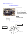
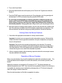
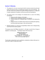
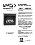
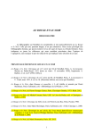
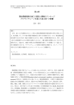
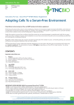
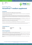
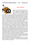
STREX Cell Strain Instrument
Cat. # ST-150
Serial # 20B-00005
User Manual
B-Bridge International, Inc.
320 Logue Avenue
Mountain View, CA 94043, USA
Phone: 650-969-7727 Fax: 650-969-7737
Email: [email protected]
www.b-bridge.com
Contents
Section 1: Main Components.............................................................................................................3
Cell Strain Instrument.........................................................................................................................3
Silicone Strain Chamber......................................................................................................................3
Control Unit Front Panel....................................................................................................................4
Control Unit Back Panel ....................................................................................................................4
Section 2: Use of the Cell Strain Instrument…………………………………………………….5
Preparation of the Cell Strain Instrument.........................................................................................5
System Operation ..............................................................................................................................5
Culturing Cell in the Silicone Chambers ..........................................................................................6
Preparation of Silicone Chambers....................................................................................................6
Section 3: Strain Parameters .............................................................................................................8
Section 4: FAQ.......................................................................................................................................9
Section 5: References........................................................................................................................11
Section 6: Safety Instructions..........................................................................................................13
Section 7: Warranty............................................................................................................................15
2
Section 1: Main Components
Cell Strain Instrument (Stretch Unit)
Strain chamber brackets
Each chamber is mounted on four brackets.
Fan
Chamber Length Adjustment Knob:
To freely rotate the knob, the power switch
must be OFF. Use the knob to adjust the
distance of the chamber brackets such that
it maintains tension on the silicone
chamber.
Motor Cable
Cable connects to Control Unit
Platform
Place platform on
top of microscope
stage for viewing.
Silicone Strain Chamber (ST-CH-04.0)
Chamber Dimensions
20mm x 20mm x 10mm
31m
m
Chamber membrane
10m
m
thickness = 0.1mm
18m
m
4 places for pins
40m
25m
m
3
Control Unit Front Panel
Main Power Switch
Start and Stop Button
Use to start or stop the stretching action.
Frequency Selector (left digit)
Use upper and lower buttons to adjust frequency
Stretch Ratio Selector (right digit)
Use upper and lower buttons to increase and
decrease strain ratio.
Control Unit Back Panel
Power Cable Outlet
Fuse
4
Motor Cable Outlet
Connects the Stretch Unit to the Control
Unit via Motor Cable
Section 2: Use of the Cell Strain Instrument
Preparation of the Cell Strain Instrument
Before using the Stretch Unit, sterilize the unit — especially the chamber mounting area — using
ethanol-immersed swabs.
System Operation
Operation of the Cell Strain Instrument is very straight forward and intuitive. Below are the basic
steps to use this instrument. The step motor that moves the chamber brackets is made to
operate 15 minutes continuously. It is not recommended to extend the use of the motor
beyond 15 continuous minutes because of possibly overheating and burning out the
motor.
►Set-up the Stretch Unit and Control Unit
1.
Connect the Stretch Unit to the Control Unit by the Motor Cable. This supplies electricity to the
Stretch Unit and enables the two units to communicate.
2.
Connect the Control Unit to the power supply (240 V) by the Power Cable.
3.
Turn on the Power Switch to start operation. The Power Switch will light up and the Stop
Button will flash.
BEWARE: The Fan that cools the step motor will be rotating. Do not obstruct the fan blades
with any objects.
4.
If the electrical system is operating properly, turn OFF the Power Switch.
5.
Make sure that the microscope is level on the work bench and the Stretch Unit when placed
on the microscope is also level.
►Start Cell Stretching
1. Make sure that the electrical/communications for the Stretch and Control Units are properly
set-up.
2. Load the chambers into the Stretch Unit by inserting the pins on the bracket into the four
corners of the chamber. The Power Switch must be OFF to freely rotate the Chamber
Length Adjustment Knob.
3. Rotate the Chamber Length Adjusting Knob counterclockwise to create tension on the
chamber. The membrane at the bottom of the chamber should be taut.
5
4. Turn on the Power Switch.
5. Select the desired stretch ratio and frequency on the Control Unit. Programs are outlined in
Section 3.
6. Press the START button to start the stretch cycle. During the action cycle, the green light will
be illuminated. To STOP movement at any time, press the STOP button.
7. Do not change the Stretch Ratio or Frequency parameters during the operation of a
stretch cycle. Press the STOP button and wait for the program to complete the final
stretch-contract sequence (returning to the original start position) before initiating the
next stretch parameter. Changing parameters during a stretch cycle may damage the motor.
8. After a few minutes of running a stretch program, stop the cycle and check the condition of the
cells. If the cells have not detached from the membrane, proceed with your experiment. If the
cells are detached, the chamber coating was probably insufficient. Recoat the chambers.
Culturing Cells in the Silicone Chambers
1.
Seed cells at the appropriate concentration in a freshly coated chamber.
Important: It is critical to not over expose the cells to dissociation enzymes. Cells should be
treated in the same manner (type and concentration of enzyme, temperature, and exposure
time) for all experiments.
Important: Cells should not be seeded at a high density in the chambers. For example,
epithelial cells often form a cell-sheet and the cell-cell adhesion seems to be stronger than a
cell-surface adhesion. When this happens cells may detach from the chamber. Additionally,
cultures that are grown over a week in the chambers may detach.
2.
After an overnight incubation without stretching, inspect the cells with a microscope to ensure
they have adhered to the chamber.
Preparation of Silicone Chambers
Before using the chambers, they should be sterilized and coated with a cell adhesion matrix. The
coating procedures can be adapted for use with other matrices, such as elastin, pronectin, and
laminin.
Sterilize the chambers in an autoclave for 20 minutes at 121°C. The silicone chambers can
withstand temperatures up to 180°C. Use of an autoc lave is preferable. However, if an autoclave is
not available, the chambers may be sterilized by submerging them in 70% ethanol, rinsing with
water, then drying in a sterile environment.
Place the sterile chambers in a Petri dish in preparation for coating.
6
► Fibronectin Coating
Preparation of fibronectin solution:
1. Dilute human or bovine fibronectin to a final concentration of 50
to 100 ug/ml in Phosphate Buffered Saline (PBS)
PBS (per liter):
NaCl
8.00 g
KCl
0.20 g
Na2HP4(anhyd.)
1.15 g
KH2PO4 (anhyd.)
0.20 g
Coating with fibronectin solution:
Note: Dulbecco’s PBS in powder form for
1. Pour 3 ml of the fibronectin solution into each strain chamber
tissue culture applications is also
2. Incubate at 37oC for more than 30 minutes
commercially available.
3. Aspirate the fibronectin solution. If coating is successful, water
will not be repelled after removing the fibronectin solution.
4. The liquid solution can be used to coat 3 or 4 chambers before discarding.
► Gelatin Coating
Preparation of gelatin solution:
1. Add gelatin powder to PBS at a concentration of 2%
2. Autoclave the mixture to dissolve and sterilize
The PDMS (silicone) chamber is very
hydrophobic with two methyl-bases on
the surface; therefore the chamber must
Coating with gelatin solution:
1. Pour 3 ml of the gelatin solution into each strain chamber
2. Incubate at 37oC for more than 30 minutes
3. Aspirate the gelatin solution. If coating is successful, water will
not be repelled after removing the gelatin solution.
4. The liquid solution can be used to coat 3 or 4 chambers before
discarding.
► Collagen Coating (Cellmatrix 1-C, P, Type 3 or 4)
be coated with a cell adhesion matrix
such as fibronectin or collagen. In the
presence of fibronectin or collagen, cells
adhere to the matrix by integrins. Integrin
attachment is a cell specific interaction
unlike cell attachment to plastic or glass
dishes, where cells non-specifically
attach due to a charger surface.
Preparation of collagen solution:
1. Combine 1 part collagen to 10 parts HCL, pH 3, in a sterile tube
Coating with collagen solution:
1. Coat chamber with a thin layer
2. Aspirate excess
3. Dry in biological safety cabinet at 25°C or belo w. The chamber can be stored at the same
temperature.
4. Wash the chamber twice with culture medium.
5. If coating is successful, water will not be repelled.
Important: If cells are having difficulty attaching to the freshly coated chambers or are easily
detaching upon stretching, treat the chamber with a higher concentration of the extra-cellular
matrix or coat overnight.
7
Section 3: Strain Parameters
RIGHT Digit: Stretch Ratio Selector
Digit
0
1
2
3
4
5
6
7
Degree of stretch
2%
4%
6%
8%
10%
12%
15%
20%
Distance
0.4 mm
0.8 mm
1.2 mm
1.6 mm
2.0 mm
2.4 mm
3.0 mm
4.0 mm
LEFT Digit: Frequency Selector
†
Digit
0
Program
Description
1 cycle
Stretch 0.5 sec – Hold indefinitely
1 cycle
1
Square wave pattern
Stretch 0.5 sec – Hold 1 sec – Contract 0.5 sec – End
1 cycle
2
Square wave pattern
Stretch 0.5 sec – Hold 3 sec – Contract 0.5 sec – End
1 cycle
3
Square wave pattern
Stretch 0.5 sec – Hold 10 sec – Contract 0.5 sec – End
1 cycles/minute
4
Square wave pattern
Stretch 0.5 sec – Hold 29.5 sec – Contract 0.5 sec – Hold 29.5 sec – Repeat
6 cycles/minute
5
Square wave pattern
Stretch 0.5 sec – Hold 4.5 sec – Contract 0.5 sec – Hold 4.5 sec – Repeat
20 cycles/minute
Square wave pattern
6
Stretch 0.5 sec – Hold 1 sec – Contract 0.5 sec – Hold 1 sec – Repeat
60 cycles/minute*
7
Square wave pattern
Stretch 0.5 sec – Contract 0.5 sec – Repeat
†
sec is the abbreviation for seconds
* 60 cycles/minute is the maximum speed at which the instrument can operate. At this speed the square wave
pattern does not have a hold time.
8
Section 4: FAQ
Q1: What are the characteristics of the silicone chamber?
A1: The strain chamber is made from silicone elastomer consisting of polydiethylsiloxane as its major
component. The chamber surface is strongly hydrophobic and cells have difficulty attaching to it; therefore,
the chamber surface should be coated with an extra-cellular matrix like fibronectin, collagen, laminin, or
gelatin before cultivation.
Q2: Cell attachment on the stretch chamber is not consistent.
A2: There may be wrinkles or bubbles on the bottom surface of the strain chamber when seeding cells.
Although the chamber is carefully made not to have wrinkles on it, some products might have little wrinkles
due to its thin structure. We recommend the following steps. Using a Petri dish that is large enough to
hold the chamber, add a small volume of ethanol. Place one end of the chamber in the ethanol and lay the
chamber down by slowly moving toward the opposite end of the chamber without trapping air bubbles
between the dish and the chamber. The thin layer of ethanol between the dish and the chamber will remove
any wrinkles in the chamber membrane. Allow the ethanol to evaporate before spreading your cell
suspension in the chamber.
Q3. Cell attachment on the stretch chamber was confirmed by microscopy. But the cells detached from the
chamber surface after stretching the cells.
A3: Try seeding your chambers at a lower concentration of cells. In typical cell culture dishes, over-confluent
cells generally adhere to neighboring cells rather than to the base matrix (dish surface). This behavior is
exaggerated when an excess number of cells are seeded into a stretch chamber.
A second possibility for cell detachment is that the cells were damaged by enzyme treatment such as trypsin.
The damaged cells may attach to surfaces by non-specific binding and are not specifically bound to the
extra-cellular matrix coating on the chamber; therefore, time, concentration, and temperature for the enzyme
treatment should be optimized to reduce cell damage.
A third possibility is insufficient coating of the chamber preventing the cells from attaching to the chamber. In
this case, longer coating time is recommended. Some researchers coat the chamber with two or more kinds
of the extra-cellular matrix materials to increase binding effectiveness.
Q4: How long can cells be stretched?
A4: The duration depends on cell strain and condition. However, the step motor in a ST-150 and ST-195 is
9
made to operate for 15 continuous minutes. The ST-140 models can run for hours to days if the cooling
system is on.
Q5: How can I obtain protein or mRNA samples from the cells attached to the silicone membrane?
A5: (1) Proteins for Western blotting: Wash the cells once with PBS. Add SDS-PAGE sample loading dye
directly into the chamber, and collect the cell extract by using a cell scraper.
(2) Proteins for Immunoprecipitation: Wash the cells once with PBS. Add cell extract buffer directly into the
chamber, and collect the cell extract by using a cell scraper.
(3) RNA: Wash the cells once with PBS (for RNA preparation). Add RNA extraction buffer directly into the
chamber, and collect the cell extract by using a cell scraper.
Q6: I want to use recombinant cells for an experiment.
A6: Direct transfection of cells in the chamber may be possible. However, transfection itself may damage the
cells, which may make getting clear image data difficult. We recommend performing the transfection in a
standard culture dish then transferring the recombinant cells into the strain chamber.
Q7: Cells seem to be crowded in the center instead of being uniformly distributed throughout the chamber.
A7: Vibration from the incubator may disrupt the distribution of the cells. We recommend gently rocking the
chamber 15 mins after seeding your cells.
10
Section 5: References
1.
Effects of repetitive stretch stimulation on neonatal rat cardiocytes in vitro, K. Kada, K. Yasui, K. Naruse, and J.
Toyama. Environmental Medicine, 40: 69-72, 1996.
2.
Inhibitory action of repeated stretch stimulation on apoptosis in neonatal rat cardiocytes., K. Yasui, H.
Shimano, K. Kada, K. Naruse, and J. Toyama. Environmental Medicine, 40: 175-177, 1996.
3.
Mechanosensitive ion channels: Single channels vs. Whole cell activities, M. Sokabe, K. Nunogaki and K.
Naruse. Progress in Cell Research, 6:139-149, 1997.
4.
Up-regulation of integrin beta3 expression by cyclic stretch in human umbilical endothelial cells., M. Suzuki, K.
Naruse, Y. Asano, T. Okamoto, N, Nishikimi, T. Sakurai, Y. Nimura, and M. Sokabe. Biophys. Biochem.
Res.Com., 239:372-376, 1997.
5.
Mechanotransduction and intracellular signaling mechanisms of stretch-induced remodeling in endothelial
cells, Masahiro Sokabe, Keiji Naruse, Shorei Sai, Takako Yamada, Keisuke Kawakami, Masumi Inoue,
Kichiro Murase and Motoi Miyazu. Heart Vessel, S12:191-193, 1997.
6.
Involvement of SA channels in orienting response of cultured endothelial cells to cyclic stretch., K. Naruse, Y.
Yamada, and M. Sokabe. Am. J. Physiol., 274:H1532-H1538, 1998.
7.
Up regulation of COX expression by uni-axial cyclic stretch in human lung fibroblast cells, T. Kato, N. Ishiguro,
H. Iwata, T. Kojima, T. Ito and K. Naruse. Biophys. Biochem. Res.Com., 244:615-619, 1998.
8.
Pp125FAK is required for stretch dependent morphological response of endothelial cells. K. Naruse, T.
Yamada, X. Sai, M. Hamaguchi, and M. Sokabe. Oncogene, 17:455-463, 1998.
9.
Orientation Change of Cardiocytes Induced by Cyclic Stretch Stimulation: Time Dependency and
Involvement of Protein Kinases, K. Kada,K. Yasui, K. Naruse, and J. Toyama, J. Mol. Cell. Cardio.,
31:247-259, 1999.
10. Molecular Identification of a Eukaryotic Stretch-Activated Nonselective Cation Channel, M. Kanzaki, M.
Nagasawa, I. Kojima, C. Sato, K. Naruse, M. Sokabe, H. Iida, Science, 285:882-886, 1999.
11. Activation of pp60SRC is Critical for Stretch-Induced Orienting Response in Fibroblasts, X. Sai, K. Naruse, M.
Sokabe, J. Cell Sci. 12:1365-1373, 1999.
12. SA Channel Mediates Superoxide Production in HUVECs, K. Aikawa, N. Nishikimi, T. Sakurai, Y. Nimura, M.
Sokabe, K. Naruse, Life Sci. 69 (15):1717-1724, 2001.
13. Uni-axial cyclic stretch induces the activation of transcription factor nuclear factor κΒ in human fibroblast cells,
H. Inoh, N. Ishiguro, S. Sawazaki, H. Amma, M. Miyazu, H. Iwata, M. Sokabe, K. Naruse, FASB Journal,
16:405-407, 2002.
14. Mechanical stress-dependent secretion of interleukin 6 by endothelial cells after portal vein embolization:
clinical and experimental studies, M. Kawai, K. Naruse, S. Komatsu, S. Kobayashi, M. Nagino, Y. Nimura, M.
Sokabe, J. Hepatol. 37(2):240-246, 2002.
15. Calcium regulates the P13K-Akt pathway in stretched osteoblasts, T. Danciu, R. Adam, K. Naruse, M.
Freeman, P. Hauschka, FEBS Letters 536:193-197, 2003.
16. A new mechanosensitive channel SAKCA and new MS channel blocker GsTMx-4, M. Sokabe, K. Naruse, T.
11
Qiong-Yao, Folia Pharmacologica Japonica 124(3):301-310, 2004.
17. Mechanotransduction of integrin is essential for IL-6 secretion from endothelial cells in response to uniaxial
continuous stretch, A. Sasamoto, M. Nagina. S. Kobayashi, K. Naruse, Y. Nimura, M. Sokabe, Am J Physiol
Cell Physiol 288:1012-1022, 2005.
18. N-cadherin-mediated cell adhesion determines the plasticity for cell alignment in response to mechanical
stretch in cultured cardiomyocytes, T. Matsuda, K. Takahashi, T. Nariai, T. Ito, T. Takatani, Y. Jujio, J. Azuma,
Biochem Biophys Res Comm 326:228-232, 2005.
19. N-cadherin signals through Rac1 determine the localization of connexin 43 in cardiac myocytes, T. Matsuda,
Y. Jujio, t. Nariai, T. Ito, M. Yamane, T. Takatani, K. Takahasi, J. Azuma, J Mol Cell Cardio 40(4):495-502,
2006.
20. Activation of a mechanosensitive BK channel by membrane stress crated with amphipaths, Mol Membr Biol
22(6):519-527, 2005.
21. Stretch-induced cell proliferation is mediated by FAK-MAPK pathway, Life Sci 76(24):2817-2825, 2005.
22. Fabrication of reconfiguration protein matrices by cracking, X. Zhu, K. Mills, P. Peters, J. Bahng, El Liu, J.
Shim, K. Naruse, M. Csete, M. Thouless, S. Takayama, Nature Materials 4:403-406, 2005.
23. Involvement of reactive oxygen species in cyclic stretch-induced NF-κΒ activation in human fibroblast cells, H.
Amma, K. Naruse, N. Ishiguro, M. Sokabe, Brit J Pharmacol 145:364-373, 2005.
24. Viscoelastic and dynamic nonlinear properties of airway smooth muscle tissue: roles of mechanical force and
the cytoskeleton, S. Ito, A. Majumdar, H. Kume, K. Shimokata, K. Naruse, K. Lutchen, d. Stamenovic, B. Suki,
Am J Physiol Lung Cell Mol Physiol 290(6):L1227-1237, 2006.
25. Bi-phasic activation of eNOS in response to uni-axial cyclic stretch is mediated by differential mechanisms in
BAECs, H. Takeda, K. Komori, N. Nishikimi, Y. Nimura, M. Sokabe, K. Naruse, Life Sci 79(3):233-239, 2006.
12
Section 6: Safety Instructions
Please read this section carefully before using the instrument. Items in this section alert the user to
operational dangers that, if not followed, may damage the instrument or, more significantly, result in
serious injury or death of the user. To ensure safe operation of the instrument, it is therefore
imperative that you follow these instructions carefully.
Power cable
To avoid possible short circuit, shock, or fire
•
Only use the power cable provided with the Cell Strain Instrument.
•
Do not touch the cable with wet hands.
•
Do not use the machine with other voltage than that specified. In some cases, a
transformer may be used for compatibility. Inappropriate current may result in the machine
overheating, short-circuiting, and/or fire may occur.
•
Do not staple around the power cable.
•
Do not bend the cable or place heavy objects on it.
•
When pulling a connector from an outlet, pull to disconnect gently by holding its plug, not
the cable.
•
Do not plug many objects into a single electrical outlet since it may cause fire.
•
If you are using an extension cord, ensure it can withstand the total current to be used.
•
Disconnect power from the unit when it is not in use.
•
Connect the instrument to a power-surge protected outlet.
Installation Location and Environment
•
Keep the instrument on a stable, level floor or a table, secure from vibrations. Be sure
you have enough space.
•
Do not store the instrument in a humid or dusty place. Over time, excessive humidity or
dust may cause deterioration that can result in an electrical short-circuit and possibly fire.
•
Do not use the machine in a place where the temperature is excessively high. Do not
place and run the machine near a heater or in a place being exposed to direct sunlight.
•
To avoid possibly explosion, never place and run the instrument nearby the presence of
flammable solid substance, liquid, or gas. It may cause explosion or fire.
•
Use the machine in well lit conditions.
•
Do not use the machine outdoors in direct sunlight or rain, which may cause overheating
or short circuit.
13
Operational Concerns
•
Please make sure to read the manual prior to running the unit. Those who are not familiar
with the machine should not operate it.
•
Do not put your hand close to mechanical parts or alike while the unit is running.
•
Do not put any foreign substances inside the machine. Water, metal, or paper in motor
area, may cause fire or electrical shock.
•
Do not make any attempt to disassemble or modify the machine. Do not remove the
cover in an attempt to touch the mechanism inside, which may cause you an electrical
shock.
•
Please refrain from modifying the machine without our permission, you may be shocked or
injured. If you do attempt to modify the machine, the warranty on the unit is void and we
will not be responsible for any performance deterioration or unit malfunction.
•
In the case of any abnormal sound, smell, or smoke, disconnect the power immediately
and contact B-Bridge International.
•
Do not run the machine overloaded.
•
Be cautious as to your clothing and hair when operating the instrument. Baggy clothing,
neckties, necklaces, etc., can get tangled in moving parts of the unit. Take appropriate
precautions to prevent this occurrence.
•
Keep the machine clean and periodically inspect the instrument for excessive wear or
damage. Contact B-Bridge if you have any concerns.
14
Section 7: Warranty
1.
The warranty is for one year, commencing the date the customer receives the product and
includes the instrument casing, non-wearable parts, as well as, the motor and bearings. The
cell culture chambers are considered consumables, B-Bridge International, Inc. is responsible
for repair or replacement of chambers, only if they are received and found defective.
2.
The warranty does not cover damage to the instrument that is a result of the following
circumstances:
① Damage caused by dropping, or other impact.
② Damage caused by inappropriate operation of the instrument.
③ Damage resulting from an attempted repair or modification of the instrument by
the user.
④ Damage caused by unavoidable external causes such as earthquakes, lightening,
fire, flood, gas leak, power surges, or other acts of providence.
3.
B-Bridge International, Inc. is free from any responsibility for effects or loss or damages arising
from the result of the machine operation.
This warranty assures that B-Bridge International, Inc. will repair our product free of charge as
stipulated in our warranty policy. Any shipping charges will be born by buyer.
B-Bridge International, Inc.
320 Logue Avenue
Mountain View, CA 94043, USA
Phone: 650-969-7727 Fax: 650-969-7737
Email: [email protected]
The information contained herein such as specification, configuration, and data or alike in part or in
whole may be subject to change without notice.
15