1
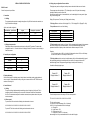
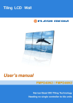
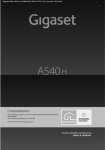
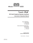
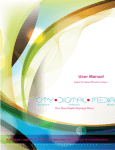
LCD Video Monitor & Video Wall
Universal User Manual
DiD
Digital Information Display
Video Monitor Models
M82S1/M70S1/M65S1/M55S1/M46S1/M40S1/M32S1/M24S1/M19S2/M19S1
Video Wall Models
PD55N3/PD46N4/PD46N3/PD46N2/PD40N2
1. CONTROLS
1.3 Introduction to Remote Control
1.1 Interface
POWER
Note: LAN port is not available for M series LCD Monitor
MODE
Select signal input!
No
Description
A
AC IN: AC POWER IN
B
RS232 INPUT/OUTPUT: RS232C serial Port
C
BNC/RGB-HV IN: (R, G, B, H, V)BNC Connector for VGA signal
D
DVI (DVI-D) IN: DVI-D Connector for digital signal input
E
VGA2(D-SUB) IN: VGA Connector for analogue signal input
F
BNC/VIDEO IN,VIDEO1 OUT: BNC Connector for VIDO signal input and
output.
G
KEYBOARD: RJ45 connector for cable remote
H
LAN: RJ45 Connector for network control (not available for M series)
I
HDMI: HDMI Connector for digital signal input
Diagram
Navigation Buttons
Press these buttons to
select
preference and MENU for
confirmation.!
2. CONNECTING
2.1 Control monitors through RS232
Monitors can be controlled by computer through RS232 cable. There are two RS232 connectors
on the monitor. (One for signals input, the other for signals output). Every monitor needs a
separate ID number to be able to be controlled via RS232.
!
1.2 Introduction to Cable Remote Buttons
2.2 Display DVI Signal
Connect the monitor and computer using a DVI-D cable, switch the signals input to DVI in
menu. Use AUDIO IN3 connector for audio input, and AUDIO OUT for audio output.
No
1
Description
Left and Right buttons a) adjust volume b) select in OSD menu c) select
in signals input d) adjust values
2
Open/Close OSD Menu or Return to Previous Menu
3
Open source input list
4
Select signal input / Down button
Diagram
!
Note: LAN port is not available for M series LCD Monitor
2.3 Display Video signal
�,
Video1 and Video2 signal input mode
1. Contrast: Adjust the contrast ratio of the picture
2. Brightness: Change luminance of the picture.
3. Color mode: You can choose different Color mode, according to your prefer. It has four
mode: USER, COLD, WARM, STANDARD
4. Aspect ratio mode: Normal, Center
5. Picture Mode: USER, STANDARD, SPORT, SOFT
Video device connected with the monitor by BNC connector. Set the signal input mode at
,
SETTING:
!
Note: LAN port is not available for M series LCD Monitor
3. ON SCREEN DISPLAY (OSD)
3.1 Instruction to signal input selection
Press MODE button to enter signals input list and use navigation buttons to make a choice.
Mode
Description
PC
Analogue signal from computer
DVI
Digital signal from computer
AV1
VIDEO signal input 1
AV2
VIDEO signal input 2
1. TEMPERATURE - Actual temperature inside the unit.
2. FAN ACTIVE - User according to the actual situation of environment to set a start
temperature. When the actual temperature is higher than the set temperature, the fan will
automatically run; when temperature inside the machine is lower than the set temperature,
fan will shut down automatically.
3. RESET:recall the default settings.
OSD
3.2 Introduction to menu
PICTURE:
,
�,
!
1. OSD LANGUAGE Press � ,
to change the kind of language.
2. MENU Display configuration horizontal position, vertical position, display time,
transparence.
3. Digital video wall adjust Stretch picture towards left /right/up/down.
perfectly spliced by software, you can use this function to adjust the screen.
Supported Resolutions
■ ADVANCE
Press “◀ , ▶” to change parameters,Press “MENU” button to save settings
For screens with a native resolution of 1920 x 1080 : MODE
STANDARD
1.
2.
3.
4.
5.
6.
7.
CLOCK - Set current time
ON TIME - Automatically power on as the time you set
OFF TIME - Automatically power off as the time you set
CURRENT X - Number of X on the video wall
CURRENT Y - Number of Y on the video wall
TOTAL X - Total number of monitors on X axis (maximum X = 12)
TOTAL Y - Total number of monitors on Y axis (maximum Y = 12)
Video signals via Video in and Video out can be daisy chained in a video wall environment,
other inputs eg: DVI-D require a separate signal to each individual screen.
Take a 3×3 wall for example, The following sketch is for your reference.
RESOLUTION
ASPECT RATIO HANDLING
INPUT SOURCE
Full-Screen
AR Aspect
Ratio
DVI
RGB
Composite
Video
VESA
640x480@60,67,72,75Hz
1920x1080
16:9
Y
Y
N
IBM
720x400@70Hz
1920x1080
16:9
Y
Y
N
VESA
800x600@56,60,72,75Hz
1920x1080
16:9
Y
Y
N
VESA
1024x768@60,70,75Hz
1920x1080
16:9
Y
Y
N
VESA
1280x720@60Hz
1920x1080
16:9
Y
Y
N
VESA
1280x960@60Hz
1920x1080
16:9
Y
Y
N
VESA
1280x1024@60Hz
1920x1080
16:9
Y
Y
N
VESA
1600x900@60Hz
1920x1080
16:9
Y
Y
N
VESA
1600x1200@60Hz
1920x1080
16:9
Y
Y
N
VESA
1920x1080@60Hz
1920x1080
16:9
Y
Y
N
OVERSCAN - Video source overscan: 3~5% / PC(DVI&VGA): No over scan
For screens with a native resolution of 1366 x 768 : MODE
!
STANDARD
RESOLUTION
ASPECT RATIO HANDLING
INPUT SOURCE
Full-Screen
AR Aspect
Ratio
DVI
RGB
Composite
Video
VESA
640x480@60,67,72,75Hz
1366x768
16:9
Y
Y
N
IBM
720x400@70Hz
1366x768
16:9
Y
Y
N
VESA
800x600@56,60,72,75Hz
1366x768
16:9
Y
Y
N
VESA
1024x768@60,70,75Hz
1366x768
16:9
Y
Y
N
VESA
1280x720@60Hz
1366x768
16:9
Y
Y
N
VESA
1280x960@60Hz
1366x768
16:9
Y
Y
N
VESA
1366x768@60Hz
1366x768
16:9
Y
Y
N
VESA
1280x1024@60Hz
1366x768
16:9
Y
Y
N
VESA
1600x900@60Hz
1366x768
16:9
Y
Y
N
VESA
1600x1200@60Hz
1366x768
16:9
Y
Y
N
VESA
1920x1080@60Hz
1366x768
16:9
Y
Y
N
OVERSCAN - Video source overscan: 3~5% / PC(DVI&VGA): No over scan
SERIAL CONTROL SPECIFICATION
4.3. Display Array configuration/Source selection
The display array can be reconfigured, and input sources selected with the same set of codes:
RS-232 Control
The message starts with a lead byte of FFh, followed by a count of ALL bytes in the message,
including the lead byte, and the count itself.
After the count comes a series of command blocks, one for each display in the array, each 4 bytes
long in the following format:
Serial Control protocol specification
1. Connection
1.1. Cabling
The connecting cable required is a straight through from a 9-pin D-Sub female at the controller, to a
9-pin D-Sub male at the display.
Display ID, Input source, Total array size, Display location in array
The Display ID value varies from 41h for display ID 1, to 7Fh for display ID 64. (Display ID + 40h)
The Input Source value is one of the following:
Serial control cable configuration
Controller End – 9-pin Female
Signal
Display End – 9-pin Male
Pin 2
Controller RX – Display TX
Pin 2
Pin 3
Controller TX – Display RX
Pin 3
Pin 5
Signal GND
Pin 5
1.2. Display Interconnection
Each display buffers and repeats the control signal on a Serial OUT connector. The same cable
configuration used in 1.1 is used to link from one display’s Serial OUT connector to the next display’s
Serial IN connector.
2. Controller port configuration
Baud Rate
9600
Data Bits
8
Parity
None
Stop Bit
1
Flow Control
None
3. Display Addressing
Since the serial control to the display array is daisy chained, each display needs a unique address in
order to control it. These addresses are set up using the on-screen menu in the SETTINGS menu, the
maximum ID setting is 64.
4. Control Protocol
4.1. Coding
The protocol coding is implemented by transmitting a series of single byte (8-bit) codes. This is
sometimes referred to as binary mode, or raw mode. All codes are shown here in hexadecimal.
No CR or LF characters are required to terminate a command, except where shown in the power
control commands.
4.2. Power control
To power ON all of the monitors the following code series needs to be sent:
01 30 2A 30 41 30 43 02 43 32 30 33 44 36 30 30 30 31 03 18 0D
To power OFF all of the monitors the following code series needs to be sent:
01 30 2A 30 41 30 43 02 43 32 30 33 44 36 30 30 30 34 03 1D 0D
Input Selected
CVBS 1
VGA/PC
CVBS 2
DVI
Input Source Value
02h
A2h
22h
42h
The Total array size value is made up of 2 parts. The first hexadecimal digit (upper 4 bits) represents
the number of displays in the horizontal direction. The second hexadecimal digit (lower 4 bits)
represents the number of displays in the vertical direction. Maximum array size is 12x12.
Examples:
For a 2x2 array the value is 22h, for a 3 wide by 2 high array the value is 32h, for a 10x10 array
the value is AAh, and for a 12x12 array the value is CCh.
The Display location value is made up in a similar manner, with the first hexadecimal digit (upper 4
bits) representing the display’s horizontal position from the left of the array, and the second
hexadecimal digit (lower 4 bits) representing the display’s vertical position from the top.
Consider the following display layout
Display ID: 1
Display Location 1,1
Display ID: 2
Display Location 2,1
Display ID: 3
Display Location 1,2
Display ID: 4
Display Location 2,2
To switch the input sources for the array to DVI the code sequence is:
FF 12 41 42 22 11 42 42 22 21 43 42 22 12 44 42 22 22
FF is the start of message
12 is the count of bytes in message (12h = 18 decimal)
41 42 22 11 is the command block for the first display:
41 – Display ID 1
42 – Input Source = DVI
22 – Total array size is 2x2
11 – Display set to location 1,1 in the array
the remaining sets of 4 byte command blocks are for the other 3 displays.