1
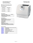
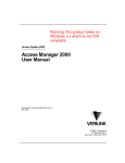
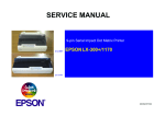
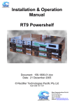
User Manual WebCSU for MiniCSU-2 / MicroCSU Systems Document: 158-1770-03 Date: 19/02/2007 Rectifier Technologies Pacific Pty. Ltd. ABN 36 058 107 707 Table of Contents 1. Introduction ................................................................................................................4 1.1 Nomenclature ........................................................................................................4 1.2 Getting Started ......................................................................................................4 1.2.1 Package Contents..............................................................................................4 1.2.2 Minimum Requirements .....................................................................................4 2. Installation ..................................................................................................................5 2.1 Installing WebCSU ................................................................................................5 2.1.1 Installing the WebCSU Unit................................................................................5 2.1.2 Installing the WebCSU Configuration Tool.........................................................8 2.1.3 Installing the WebCSU MIB................................................................................9 2.1.4 Installing the Java Runtime Engine....................................................................9 2.1.5 Installing WinCSU-2...........................................................................................9 2.2 Running the WebCSU Configuration Tool for the first time ...................................9 2.2.1 Legacy Version Of WebCSU Configuration Tool ...............................................9 2.2.2 Logging Into The WebCSU Configuration Tool ................................................10 2.3 Network Setup .....................................................................................................11 2.3.1 Network Protocols............................................................................................11 2.3.2 Network Setup & Troubleshooting ...................................................................12 3. WebCSU Configuration Tool Operation .................................................................14 3.1 Introduction..........................................................................................................14 3.2 The Main Screen .................................................................................................15 3.2.1 The Module Tree..............................................................................................16 3.2.2 The Module Information Area...........................................................................16 3.3 Pull-down Menus .................................................................................................17 3.3.1 File Menu .........................................................................................................17 3.3.2 Module Menu ...................................................................................................18 3.3.3 Tools Menu ......................................................................................................19 3.4 Pop Up Windows .................................................................................................20 3.4.1 WebCSU Module Settings Window..................................................................20 3.4.2 User Management Window..............................................................................30 3.4.3 Reporting Options ............................................................................................30 4. SNMP.........................................................................................................................31 4.1 SNMP MIB Structure ...........................................................................................31 4.1.1 psIdent .............................................................................................................31 4.1.2 csuStatus .........................................................................................................31 4.1.3 csuTest ............................................................................................................32 158-1770x.doc Page 2 of 39 19/02/2007 4.1.4 csuSysConfig ...................................................................................................32 4.1.5 csuParam.........................................................................................................32 4.1.6 csuAlarmLog ....................................................................................................32 4.1.7 smrStatus.........................................................................................................33 4.1.8 smrParam ........................................................................................................33 4.1.9 cellVoltages......................................................................................................33 4.1.10 siteMonitorStatus .............................................................................................33 4.1.11 siteMonitorParam.............................................................................................34 4.1.12 csuTraps ..........................................................................................................35 4.1.13 release .............................................................................................................36 5. SNTP..........................................................................................................................36 6. WinCSU-2 Connectivity ...........................................................................................36 7. Web Interface............................................................................................................37 8. Telnet.........................................................................................................................37 8.1 Server Configuration (Network Configuration) .....................................................38 8.1.1 IP Address .......................................................................................................38 8.1.2 Gateway Address.............................................................................................38 8.1.3 Net Mask..........................................................................................................38 8.1.4 Configuration Port ............................................................................................38 8.1.5 Refresh Rate....................................................................................................38 9. 8.2 Exit without save..................................................................................................38 8.3 Save and exit.......................................................................................................39 Product Support.......................................................................................................39 158-1770x.doc Page 3 of 39 19/02/2007 1. Introduction The WebCSU system is an embedded network server, attached to either a MiniCSU-2 or MicroCSU system, that allows the RTP power system controller to be accessed from anywhere in the world. WebCSU runs over any IP network, including the Internet, and allows monitoring of the site via RTP’s WinCSU-2 based protocol, SNMP and HTTP. The SNMP interface allows alarm notification via traps, and read only access to all of the system controller parameters, from a remote Network Management System. The WebCSU unit allows you to setup which alarms you want reported as SNMP traps. Using RTP’s monitoring and control program, WinCSU-2, you can configure and monitor the system controller, on up to 2 separate computers, at any given time. Or alternatively, you can monitor the system controller’s status, via a web browser with no additional software required. 1.1 Nomenclature Throughout this manual the following styles are used to differentiate between pull-down menus and selections. File Menu Denotes a pull down menu from the menu bar at the top of the window Print Denotes a selection option within a pull down menu CSU Denotes a short-cut button on the toolbar below the menu bar 1.2 Getting Started 1.2.1 Package Contents • WebCSU Hardware o RTP (PCB C5420Aa) • CD, containing o Installation & Operation Manual (this document); o Configuration Tool Installation; o WebCSU MIB; o Java 1.4.2 Runtime Engine; • The lastest Lantronix XPort Installer, available from the Lantronix website: http://www.lantronix.com/. 1.2.2 Minimum Requirements 1.2.2.1 Minimum PC Requirements The following equipment is required to establish a connection to a CSU: • Computer running Windows 98/Me/2000/XP with at least 10MB of disk space available. The WebCSU Configuration dialogues are best viewed at a screen resolution of 1024x768 or higher. The minimum screen resolution required is 800x600. • A network connection to the WebCSU product 158-1770x.doc Page 4 of 39 19/02/2007 • For HTTP Interface users: • Internet Explorer 6.0 • Java 1.4.2 Runtime Engine for any computers accessing the HTTP interface 1.2.2.2 Minimum MiniCSU-2/MicroCSU Requirements The following are the minimum requirements for the MiniCSU-2 • MiniCSU-2 with hardware version: C074-b; or o 10 Fin, 1cm heat-sink attached to N173 • MiniCSU-2 BIOS version G1247af • MiniCSU-2 Flash version G1233cc • The MiniCSU-2 or MicroCSU unit must have the latest RTP changes made (9-7-04 update / RT0740Fa.doc minimum) • MicroCSU Back panel with EN0007 applied. 1.2.2.3 Minimum User Requirements For installation of the WebCSU unit, it is recommended that the installer has some working knowledge of general network settings, the TCP/IP and UDP/IP protocols, and also have access to network information. If SNMP is to be installed, it is highly recommended that the installer has knowledge of the Network Management System to be used. 2. Installation 2.1 Installing WebCSU 2.1.1 Installing the WebCSU Unit The WebCSU Unit should be installed onto the magazine of the MiniCSU-2 rack. To install, plug the attached cable into the backplane plug, and insert the screws. A mounted WebCSU module in a MiniCSU-2 Rack, looking from above 158-1770x.doc Page 5 of 39 19/02/2007 A mounted WebCSU module in a MiniCSU-2 Rack, looking from behind There are two methods of setting your WebCSU unit up on your network. • XPort Installer • ARP and Telnet (Advanced Users) Both these methods will allow you to set the static IP address of the unit. See Section 2.3 for an explanation on addressing. Each of these methods has its advantages, and you should choose the method that suits your particular needs. In each case you will need to know the Ethernet address (also referred to as hardware address or MAC address) of the unit. The interface module of the unit (into which the network is plugged) ships with a product information label affixed to it. The product label contains information about your specific unit, such as its bar code, serial number, product ID (name), product description, and Ethernet address. 2.1.1.1 XPort Installer To configure your WebCSU module’s IP address using the XPort Installer, you will need to know the MAC address of your WebCSU module to identify the unit. 2.1.1.1.1 Preparations for local address set up • From your network administrator obtain new IP address. Also ask for your network class. • Retrieve the MAC address for the WebCSU module • Connect PC to the controller’s network interface (directly or via a network). • Power-up the controller. 158-1770x.doc Page 6 of 39 19/02/2007 • Start XPort Installer program. 2.1.1.1.2 Local IP Address set up procedure • On the Xport Installer toolbar, click the “Search” button to find the WebCSU module attached to the network. • Identify the found module using the WebCSU module’s MAC address, then highlight the module in the list • On the XPort Installer toolbar, click the “Assign IP” button • Enter the assigned IP address for the WebCSU module • Click “OK” button. • The program will then take a few seconds, and should return either a success message, or a failure message. • If the program returns a failure message, check the details of the unit, (i.e. MAC address, and assigned IP address), and make sure there is no other device with the assigned IP address on the network. • On the XPort Installer toolbar, you can now click “search”, and a list of your WebCSU units will be presented. Look for the unit you have just programmed, to ensure the unit is using the correct IP address. 2.1.1.2 Setting the IP Address using ARP and Telnet The procedure described below is recommended for advanced users with an understanding of network operations. 2.1.1.2.1 Preparations for local address set up • Obtain a new static IP address from your network administrator. Also ask for your network class. • Connect PC to the controller’s network interface (directly or via a network). • Power-up the controller 2.1.1.2.2 Local IP address set up procedure The following section is an excerpt from Lantronix "Embedded Integration Kit" Revision D 06/03/02, Part Number 900-226. The unit’s IP address must be configured before a network connection is available. If the unit has no IP address, you can use the Address Resolution Protocol (ARP) method from Windows-based systems to assign a temporary IP address. If you want to initially configure the unit through the network, follow these steps: 1. On a Windows-based host, create an entry in the host' s ARP table using the intended IP address and the hardware address of the unit, which is found on the product label on the bottom of the unit. arp -s 191.12.3.77 00-20-4A-xx-xx-xx Notes: 158-1770x.doc Page 7 of 39 19/02/2007 i. The IP address used here is an example and a value within the range of allowable IP addresses in your network may need to be used. The DOS command ipconfig will display the IP address of the Windows-based host machine. ii. For the ARP command to work on Windows 95, the ARP table on the PC must have at least one IP address defined other than its own. 2. If you are using Windows 95, type ARP -A at the DOS command prompt to verify that there is at least one entry in the ARP table. If the local machine is the only entry, ping another IP address on your network to build a new entry in the ARP table; the IP address must be a host other than the machine on which you are working. Once there is at least one additional entry in the ARP table, use the following command to ARP an IP address to the unit: arp -s 192.168.0.97 00-20-4a-xx-xx-xx 3. Open a Telnet connection to port 1. The connection will fail quickly, but the unit will temporarily change its IP address to the one designated in this step. telnet 192.168.0.97 1 4. Finally, open a Telnet connection to port 9999, and press Enter within three seconds to go into Setup Mode. If you wait longer than three seconds, the unit will reboot. telnet 192.168.0.97 9999 5. Set all required parameters Note: The IP address you just set is temporary and will revert to the default value when the unit 's power is reset unless you log into the unit and store the changes permanently. Refer to the chapter on configuration for instructions on permanently configuring the IP address. Lantronix, Inc, 2002, all rights reserved, used herein by permission from Lantronix. 2.1.2 Installing the WebCSU Configuration Tool If you are using Windows 2000 or XP, please ensure you are logged into an account with administrative access before installing. If you are not sure, please consult your network administrator. • Insert the CD into the CD-ROM drive. • The CD will auto-play to install the configuration software • Follow the prompts during the installation procedure. At the completion of installation, a WebCSU Configuration shortcut icon will be added to the Start/Program menu. 158-1770x.doc Page 8 of 39 19/02/2007 2.1.3 Installing the WebCSU MIB The WebCSU MIB has been provided to allow integration into the user’s Network Management System. Please consult the network management system’s help for directions on how to compile and install the MIB. 2.1.4 Installing the Java Runtime Engine The Java Runtime Engine version 1.4.2 has been included on the CD-ROM. This is the minimum requirement to be able to use the HTML based monitoring page. • Insert the WebCSU Package CD into the CD-ROM drive. • Open Windows Explorer • Select the CD-ROM drive. • Open the Java Runtime folder • Run java_rte_1_4_2.exe 2.1.5 Installing WinCSU-2 Please refer to the WinCSU-2 Manual for installation procedure. If you wish to be able to change the TCP/IP Port that WinCSU-2 will communicate on, you must use WinCSU-2 version G1277db or above. 2.2 Running the WebCSU Configuration Tool for the first time If you are using Windows 2000 or XP, it is advised that you run the program under the username with which you will mostly run the program in the future. 2.2.1 Legacy Version Of WebCSU Configuration Tool Legacy versions of the WebCSU Configuration Tool present the user with a request for a username, as follows: Key in the username, and press OK. On the next screen, you will be given a Program ID on the title bar, and the program will request an Unlock Code. 158-1770x.doc Page 9 of 39 19/02/2007 To retrieve this code, you need to email [email protected] with your company name, the username typed into the previous screen, and the program ID, found in the title bar of this window. You can press cancel to exit the program, until you retrieve this code. This security code is a one time only unlock. This feature is to ensure that the configuration tool cannot be installed and run on any unauthorised computers. The username entered in the above screen is not the username that will be used for log in to the system. After the application has been unlocked, the program will request your general username and password on the following screen. These details will be emailed to you along with the registration code. 2.2.2 Logging Into The WebCSU Configuration Tool This screen will appear every time you run the configuration tool. It is to ensure that no unauthorised user can log in to the system. This prevents unauthorised users from making critical changes to any WebCSU units. The default password is available by contacting [email protected]. Please change the default password immediately By accessing the User Management option of the Tools menu (see Section 3.3.3.1). NOTE: 158-1770x.doc Page 10 of 39 19/02/2007 Every attempt to log in to the application is logged in the system event log, and also sent to a syslog server on the network. (See Section 3.4.3, for more details on Reporting Options). 2.3 Network Setup DISCLAIMER This section describes some tips and troubleshooting for the installation of a WebCSU unit on a user’s network. Rectifier Technologies Pacific accepts no responsibility for any errors or problems that occur on a user’s network during the installation of a WebCSU unit. Each user’s network is unique, and as such, an overall solution is not available. If you do not have experience maintaining and configuring your network, or do not have sufficient authorisation, it is STRONGLY RECOMMENDED that you contact you network or systems administrator to either help, or configure this for you. 2.3.1 Network Protocols WebCSU is designed to allow a user to remotely monitor the system controller, over an IP based network. It uses 2 widely used protocols, known as the TCP and UDP protocols. Although it is not essential to understand these protocols in depth, a basic knowledge of these protocols is recommended, to assist the user in the setup and any troubleshooting of network issues. The Transmission Control Protocol (TCP) and the User Datagram Protocol (UDP) are both widely documented on the Internet, and online tutorials are readily available for both protocols. TCP and UDP are both IP based standards, defined under a global standards system, known as RFC (Request For Comments). TCP is defined under RFC 793 (http://www.faqs.org/rfcs/rfc793.html), the UDP is defined under RFC 768 (http://www.faqs.org/rfcs/rfc768.html), and the IP standard is available in RFC 791, (http://www.faqs.org/rfcs/rfc791.html). The TCP and UDP standards are used as a method of encapsulating data from network applications for transport. The IP standard is essentially a method for addressing computers, and other network devices, using a standard addressing scheme. The combination of these standards allows every computer to allow simultaneous communications on each device, over different channels. 2.3.1.1 Addressing Schemes A key notion of the TCP/IP and UDP/IP standards is the addressing scheme. An IPv4 address is a 32 bit address, broken up into 4 bytes. It is normally represented as 4 sub sections, and displayed as such: xxx.xxx.xxx.xxx, where each xxx is an integer in the range 0 – 255. There are 3 main classes of network addresses. 158-1770x.doc Class Range Start Range End Subnet Mask Class A 1.0.0.0 127.255.255.255 255.0.0.0 Class B 128.0.0.1 191.255.255.255 255.255.0.0 Class C 192.0.0.0 233.255.255.255 255.255.255 Page 11 of 39 19/02/2007 Class A networks are fairly major networks, and generally used by military or governments bodies. Class B networks are normally used for large companies, with a lot of computers on the Internet. Class C networks are reserved for small – medium companies. There are 4 exceptions to the above. The IP address 127.0.0.1 is used exclusively as a loop-back address, also the following 3 ranges are used as internal network addresses only, and cannot be used on the Internet. Class Range Start Range End Class A 10.0.0.0 10.255.255.255 Class B 172.16.0.0 172.31.255.255 Class C 192.168.0.0 192.168.255.255 2.3.1.2 Ports Ports are an integral component of the TCP and UDP standards. For each standard, there are 65535 ports that can be used to access the network device. Some of the ports are defined, (known as the ‘Well Known Ports’), some are reserved, and some are free to be used. An example of the use of ports, is when an Internet browser, (such as Internet Explorer or Netscape), requests a web page, a TCP connection is established between the 2 computers. However, if the connection were established between the 2 computers, and not ports of the 2 computers, the computers would then be effectively closed to any other incoming connections. So instead, the browser connects to a single port (in the case of HTTP, this is port 80). This allows both computers to still accept any incoming connections on any of the other open ports they have. One good way to look at these ports is like doors to a building. You have an address for the building, which is your IP address, as described above. The ports then become the entries to the building. Without making a connection to the port, you cannot enter. 2.3.1.3 TCP versus UDP TCP and UDP are the most commonly used IP based protocols in operation today. They are however, different in their basic makeup. TCP establishes a connection between 2 computers, which is held open for as long as the connection is needed. This is analogous to calling somebody on a telephone. Every packet is tracked through the network, and if any packets are lost, the protocol knows to request a resend of the packet immediately. UDP sends a packet through the IP based network to the receiver, similar to sending a letter to somebody via postal mail. There is no connection made between the 2 computers, and no absolute assurance that the packet will reach the intended destination. WebCSU uses both of these protocols for different tasks. 2.3.2 Network Setup & Troubleshooting When installing the WebCSU unit onto your network, you should ask some basic questions before beginning, which will assist you with the installation. What IP Address should the unit be? What is the Subnet mask? 158-1770x.doc Page 12 of 39 19/02/2007 What is the default gateway’s IP address? Is there a firewall? Do I use a proxy server? 2.3.2.1 WebCSU IP Address The IP Address of each WebCSU unit is static. This means it cannot be dynamically given an IP address on boot up, using a DHCP server. You need to assign an IP address to the unit, and ensure that the IP address you give it is unique on the network. To assign an IP address to the WebCSU unit, see Section 2.1.1. 2.3.2.2 Subnet Mask Each IP based network has a subnet mask used on it. The subnet mask usually corresponds to the class of the network, as described in Section 2.3.1.2. This will need to be changed to reflect the subnet mask used in your particular network. TIP: Use the Windows™ command line tool ipconfig to discover your subnet mask. 2.3.2.3 Gateway IP Address The gateway IP address is required if you will be communicating with computers that are not on the current LAN connection. A gateway is generally a computer, router, or bridge, which connects a PC, or network device to another network, such as the Internet. TIP: Use the Windows™ command line tool ipconfig to discover your gateway IP address. 2.3.2.4 Firewalls Firewalls are devices that block incoming (and sometimes outgoing) packets from accessing your network. It is a method of stopping any network ‘hacking’. In current day systems, firewalls are in common use with most Internet connections. The way a firewall works, is it blocks any attempts to establish a connection with the network device. The connections are generally blocked when a PC or network device attempts to connect to the internal network from the Internet. Using WebCSU across the Internet without any form of encryption is NOT recommended. All data transfer is in an unprotected state, and is vulnerable to attack. Remote access across the Internet should be done via a virtual private network (VPN). To use WebCSU across the Internet, you must ensure that certain ports are available for connection. Most of these ports are configurable, such as the WinCSU-2 connection ports; the web interface connection port and the configuration and firmware upgrade ports (see Section 3.4.1.4). However, some ports are not configurable, such as the SNMP trap (UDP Port 162) and SNMP monitoring ports (UDP Port 161), and the HTTP connection ports (TCP Port 80). To utilise the features of WebCSU, you will need to ensure that all ports you decide to use are open to the Internet For a full list of the TCP and UDP http://www.iana.org/assignments/port-numbers port assignments, please refer to: Each firewall has its own way of configuring ports for usage. Please refer to the firewall manuals for instructions on how to open ports. 158-1770x.doc Page 13 of 39 19/02/2007 2.3.2.5 Proxy Server A proxy server is a method of speeding up the loading of web pages, by caching (or keeping a copy of) the web page on a local server. It generally operates from an Internet Service Provider’s network, although some companies maintain there own. When a web page is loaded, it is cached into the proxy server. Then, if the same webpage is requested again within a certain time frame, the page from the proxy server is sent again, reducing the time to get the page. You should avoid using a proxy server with the WebCSU unit. This is because when a proxy server is used, some of the pre-processing that occurs before the page is returned does not get redone, and as such, some changes that may have occurred, may not be reflected in the reloaded web page. TIP: Internet Explorer allows the proxy setting to be switched off or excluded for particular IP addresses, under the Tools Menu, Options, Connections Tab, LAN Settings, Advanced. 3. WebCSU Configuration Tool Operation 3.1 Introduction The WebCSU Configuration Tool allows users to keep track of the configuration of each WebCSU module, on one or more PC’s. This tool allows the user to create regions and locations, and organise these units in a tree structure, for easy sorting and maintenance. Using this tool, a user can download the configuration from, or upload the configuration to any WebCSU module that it has network access to. This may range from a WebCSU unit on a local area network (LAN), to using a wide area network (WAN) such as the Internet to access a module on the other side of the world. The tool also allows the user to update the WebCSU module with updated web page modules and firmware updates, and the MiniCSU-2/MicroCSU firmware from a remote location. 158-1770x.doc Page 14 of 39 19/02/2007 All the configuration information for each module is saved onto the local hard disk, and can be backed up accordingly. The configuration utility also provides traceability, as it logs important information to the system event log, and can also be configured to send syslog messages to a network syslog server. 3.2 The Main Screen The main screen allows the user to create and maintain many WebCSU modules, in various locations. It can show the configuration for each module listed, and gives access to edit each module’s settings via the menu system. 158-1770x.doc Page 15 of 39 19/02/2007 3.2.1 The Module Tree The module tree allows the user to define an organisational tree, listing all the WebCSU modules that will be accessed by the configuration tool. Using the Add Region and Add Branch buttons, the user can define regions based on geographical location, or logistical information. The user can delete a region or branch by selecting the item and pressing the delete key or using the Delete item on the right-click pop-up menu. 3.2.2 The Module Information Area There are 4 important sections of the Site Information area. 3.2.2.1 Module Name The module name is a configurable label set by the user. 3.2.2.2 IP Address The IP Address of the module that you wish to connect to, is set here. TIP: If you wish to upload the same module configuration to more than one unit, create a template and upload to each unit by adjusting the IP Address each time. 3.2.2.3 Port No. The port that the configuration utility will connect to is set here. This is the port you wish to connect to during the next configuration upload or download. TIP: This detail needs to be changed when you change the configuration port of the WebCSU. 158-1770x.doc Page 16 of 39 19/02/2007 *WARNING* The configuration port that the WebCSU module uses is NOT changed here. To change the configuration port the WebCSU module uses, refer to Section 4.1.1.4. 3.2.2.4 Module Information Window The module information window allows the user to quickly view a module’s settings. This section will give you a break down of all the settings that can be changed via the Module Properties menu. There is some additional data displayed in the site information window. These details are saved locally on the PC, and are not transferable between WebCSU and the configuration tool. The additional data includes; 3.2.2.4.1 Last Configuration File Write Date Shows the last date the configuration was written to the WebCSU module. 3.2.2.4.2 Last WebCSU Firmware Write Date Shows the date of the last firmware update on the WebCSU. 3.2.2.4.3 Last WebCSU Firmware Filename Shows the last firmware file filename that was uploaded to the WebCSU Module. 3.2.2.4.4 Last WebCSU Webpage Write Date Shows the date of the last webpage update on the WebCSU. 3.2.2.4.5 Last WebCSU Webpage Filename Shows the last webpage filename that was uploaded to the WebCSU Module. 3.2.2.4.6 Last MiniCSU-2 Firmware Write Date Shows the date of the last firmware update on the MiniCSU-2. 3.2.2.4.7 Last MiniCSU-2 Firmware Filename Shows the last firmware filename that was uploaded to the MiniCSU-2. This information is logged in the system event log, and reported to a syslog server, if configured. 3.3 Pull-down Menus The pull-down menus provide access to all the user selectable functions of the WebCSU configuration tool. This section describes the function of each pull-down menu and its subitems. 3.3.1 File Menu The File menu provides the ability to print hardcopies of module settings, save the configuration information, and exit the program. The functions available in the File Menu in listed order are as follows: 158-1770x.doc Page 17 of 39 19/02/2007 3.3.1.1 Save Saves any changes to module configurations to the local disk for future reference. The user will be asked to save on exit, but to safe guard changes in the meantime, they should use the Save menu option on a periodic basis. 3.3.1.2 Print Prints the currently selected Site Information. The Print Dialogue appears, allowing the user to select the appropriate printer and print properties. 3.3.1.3 Exit Exits the WebCSU program and returns to the operating system 3.3.2 Module Menu The Module menu provides access to the configuration properties and functions of the WebCSU Module selected. The functions available in the Module Menu in listed order are as follows: 3.3.2.1 Properties Opens the module parameters window that displays and allows editing of the currently selected WebCSU module parameters. See Section 3.4.1 for further detail. 3.3.2.2 Configuration From WebCSU Creates a connection to the currently selected WebCSU module, and downloads the live configuration information from the module. 158-1770x.doc Page 18 of 39 19/02/2007 3.3.2.3 Configuration To WebCSU Creates a connection to the currently selected WebCSU module, and uploads the configuration information to the module. This operation will result in the WebCSU module resetting, and is logged in the system event log, and to the syslog server, if configured. 3.3.2.4 Firmware To WebCSU Allows the user to upload the latest firmware provided by Rectifier Technologies Pacific, to the WebCSU module. This operation will result in the WebCSU module resetting, and is logged in the system event log, and to the syslog server, if configured. When selected, a dialog box will open, requesting the file to be uploaded, which will be of type .rom *WARNING* This function affects the WebCSU firmware and as such, may cause malfunctions of the WebCSU unit. Please ensure the correct software is uploaded to the WebCSU module, and that Rectifier Technologies Pacific has provided the software. Rectifier Technologies Pacific accepts no responsibility for any errors caused by uploading incorrect firmware files. 3.3.2.5 Webpage to WebCSU Allows the user to update the web page files on the WebCSU module. When selected, a dialog box will open, that searches for .cob files, which may be uploaded to the WebCSU unit. The .cob file is a special file that packages all the html files and java files into one file. 3.3.2.6 Firmware to MiniCSU-2 Allows the user to update the MiniCSU-2 firmware from a remote location. This operation will result in the WebCSU module resetting, and is logged in the system event log, and to the syslog server, if configured. *WARNING* This function effects the MiniCSU-2 firmware and as such, may cause malfunctions of the MiniCSU-2 unit. Please ensure the correct software is uploaded to the MiniCSU-2, and that Rectifier Technologies Pacific has provided the software. Rectifier Technologies Pacific accepts no responsibility for any errors caused by uploading incorrect firmware files. 3.3.3 Tools Menu The Tools menu provides access to the program options of the WebCSU configuration tool. 158-1770x.doc Page 19 of 39 19/02/2007 3.3.3.1 User Management Opens the User Management window. This window allows the user to add or delete users, and edit user information. For more information please see Section 3.4.2. 3.3.3.2 Reporting Options Opens a window that allows the user to set the syslog reporting address. This should be the IP address of a syslog server on the network. The syslog server will then receive notifications of events, such as opening and closing of the program, user login’s, changing of user information, changing of module configurations, uploads and downloads of configurations, and uploads of firmware. 3.4 Pop Up Windows Several parameter windows have been mentioned in the previous sections where systemoperating parameters are displayed and able to be edited. The parameter windows and the function of their listed parameters are described in this section. 3.4.1 WebCSU Module Settings Window 3.4.1.1 Asset Details Tab The asset details tab provides the ability to change any details that may be required by the user to assist with asset tracking. The asset tracking details are reported via SNMP, and allow the user to discover information about the unit, such as it’s physical location, that can be accessed directly via the unit, and no external source. 158-1770x.doc Page 20 of 39 19/02/2007 3.4.1.1.1 Manufacturer This is the manufacturer of the WebCSU Unit. It corresponds to the manufacturer variable in the SNMP MIB, allowing you to configure each WebCSU unit’s manufacturer name. 3.4.1.1.2 Model The model corresponds to the model type of the WebCSU unit. Typically, this will be WebCSU, however this may change for your unit, if you wish to rename the model. 3.4.1.1.3 Name The name of the system in your power network may be stored here, for usage in the WebCSU SNMP MIB. 3.4.1.1.4 Attached Devices This is the area where you may describe any attached devices for reporting via SNMP. For instance, you may wish to show that it is a system consisting of RT7 Rectifier Technologies Pacific rectifiers. 3.4.1.1.5 Asset Tag The asset tag area is a place to keep track of the asset tag of the WebCSU unit. It may be up to 15 alphanumeric characters. 158-1770x.doc Page 21 of 39 19/02/2007 3.4.1.1.6 Install Date The install date allows you to keep track of when the power system, or WebCSU unit was installed. 3.4.1.1.7 Maintenance Date The Maintenance date allows you to keep track of the last time any maintenance was performed on the WebCSU unit, or on the power supplies. 3.4.1.1.8 Build State The build state allows the administrator to effectively describe what release version and patches have been uploaded to the WebCSU module. 3.4.1.1.9 Latitude/Longitude The Latitude and Longitude sections allow you to keep track of the co-ordinates of the system, for mapping to a larger system. These values are entered in degrees, but are displayed in GPS format when reported by the SNMP interface. To convert between the GPS format and degrees, you need to use the following equations: For Latitude: Latitude in Degrees = (gpsLatitude * 90) / ((231)-1) The latitude is given as either a positive or negative. When a positive value is given, the latitude is north. When a negative value is given, the value is south. For Longitude: Longitude in Degrees = (gpsLongitude * 180) / ((231)-1) The longitude is given as either a positive or negative. When a positive value is given, the longitude is east. When the value is negative, the longitude is west. 3.4.1.1.10 Location Location allows you to describe where the module or power supply is situated. This could be an address, or an office, etc. 158-1770x.doc Page 22 of 39 19/02/2007 3.4.1.2 Operation Tab 3.4.1.2.1 Date Format The Date Format allows you to select how the date should be displayed for the WebCSU module. 3.4.1.2.2 Estimation Factor The WebCSU SNMP reported Estimated Battery Time Remaining values only provides a crude indication of time remaining and its reliability is heavily reliant on the data the user provides. The relationship between the charge remaining and time remaining is non-linear and is dependent upon a number of factors which include: 1. Battery state of health (including: age and amount of use), 2. Environmental conditions, 3. State of charge, and 4. Magnitude of the load current. The Estimation Factor is a user-entered percentage that is used to weigh down the calculated Estimated Battery Time Remaining, which allows the user to take into account some of these factors. For instance, if there is 20 minutes battery charge remaining, the 158-1770x.doc Page 23 of 39 19/02/2007 estimation factor will allow you to reduce, that to 15 minutes by changing it to 75%. The default value is 80%. The algorithm used here is: time remaining = estimation factor * estimated charge remaining battery discharge current The user should select an Estimation Factor that gives a very conservative time remaining, which will mean that the Estimated Battery Time Remaining will expire well before the LVDS is activated causing the system to potentially fail. The user uses this functionality at their own risk. 3.4.1.3 SNMP Tab 158-1770x.doc Page 24 of 39 19/02/2007 3.4.1.3.1 Read Community The read community allows you to set the SNMP read community name. This community name is used by SNMP monitoring software, to access the SNMP variables. As a default, this value is set to public. 3.4.1.3.2 Write Community The write community gives access to change the SNMP write community. Once again, it is used in SNMP monitoring software, to allow access to variables to be set. Since WebCSU does not implement any writing of parameters, this community value is not used in this release. 3.4.1.3.3 Trap Reception Section (SNMP Host Specification) The trap reception section is where you can configure what IP addresses the traps for the system should be sent to. IMPORTANT NOTE This is also used to specify the host IP addresses that can monitor the SNMP enabled device. This is an added safety feature that allows you to control what Network Management Systems can actually monitor the SNMP agent. 3.4.1.4 Connection Setup 158-1770x.doc Page 25 of 39 19/02/2007 3.4.1.4.1 Net Mask The net mask is used by the network device to determine which computers/network devices are on the same subnet. This allows the WebCSU module to determine what packets need to be sent to the gateway, and what packets can be directly addressed. 3.4.1.4.2 Gateway IP Address A gateway device is used to route packets between two networks. For instance, the LAN and the Internet. The IP address of this device is important when a WebCSU unit will be sending packets to computers or devices that are not on the same subnet as the unit. 3.4.1.4.3 WinCSU-2 TCP/IP Port 1 & 2 The WinCSU-2 TCP/IP port settings allow you to configure which ports the WebCSU should listen on for a connection from the WinCSU-2 program. These are configurable, so that you can set these to match ports that can be opened on any firewall(s) between the WebCSU module and the monitoring PC. It is recommended that you use ports 10001 and 10002 where possible. However, if these ports are unavailable, you should choose carefully what ports are used. 3.4.1.4.4 Web Interface TCP/IP Port The WebCSU’s web page uses an embedded Java applet to monitor the power system’s information. This connects to the WebCSU unit via a specified TCP port (similar to the WinCSU-2 connection). Once again, this is configurable, to allow easy port opening on any firewalls. 3.4.1.4.5 WebCSU Configuration Tool TCP/IP Port This port allows you to change what port the configuration tool should connect to the next time it connects to the WebCSU module. This is configurable, to allow for firewalls. 3.4.1.4.6 Firmware Upgrade TCP/IP Port The firmware upgrade port describes which port will be utilized to remotely upgrade the firmware of the MiniCSU-2/MicroCSU unit. It may need to be changed, depending on the firewall settings. 3.4.1.4.7 Battery Discharge Logging TCP/IP Connection The Battery Discharge Logging TCP/IP connection describes which WinCSU-2 port will be used to report any discharge logs. Only one WinCSU-2 session can receive the battery discharge information. 3.4.1.4.8 Default Access Code The default MiniCSU-2/MicroCSU access code is used when the WebCSU unit cannot dynamically read the access code of the MiniCSU-2 or MicroCSU. This may be required if the software version of the MiniCSU-2 or MicroCSU does not support the dynamic reading of an access code. For example, if the MiniCSU-2 doesn’t support the dynamic reading of access codes, and has an access code of 2453242, then the user could set the default access code of the WebCSU module to 2453242. Then, when the WebCSU module 158-1770x.doc Page 26 of 39 19/02/2007 discovers it cannot retrieve the access code from the MiniCSU-2, the WebCSU module will begin communicating using the default access code, 2453242. However, if this default access code is incorrect, the WebCSU unit will not be able to communicate with the MiniCSU-2 unit at all. 3.4.1.4.9 Time Server The timeserver details allow you to set the WebCSU unit to use either a local SNTP timeserver, or a world SNTP timeserver. 3.4.1.4.9.1 Enabled The first option is whether the SNTP protocol will be used. If it is not enabled, the MiniCSU-2 or MicroCSU will use the time that it currently has, until it is updated by WinCSU-2. If it is enabled, the SNTP client running on the WebCSU module will update the MiniCSU-2/MicroCSU time on boot up and every 24 hours thereafter. 3.4.1.4.9.2 Time Server Host Name / IP Address The timeserver host name or IP address should be set with care. If an incorrect timeserver is given, the SNTP lookup will fail, and the time will not be updated on the MiniCSU-2/MicroCSU. IMPORTANT NOTE When you insert a host name in this section, upon closing the Module settings dialog box, the host name is resolved to an IP address. The IP address is then saved, not the host name. If the host name changes IP address, there may be an address resolution problem later. 3.4.1.4.9.3 Time Zone Settings The time zone settings describe what time zone the WebCSU unit should use. 3.4.1.4.9.4 Adjust Time for Daylight Savings If you want to the unit to use daylight savings time for the local time zone, you need to check this option. Otherwise, the standard time zone information will be used. NOTE: The unit WILL NOT automatically update for daylight savings. 158-1770x.doc Page 27 of 39 19/02/2007 3.4.1.5 Alert Selection 3.4.1.5.1 Alert Selection Section The alert selection section allows you to choose which of the available alarms will be reported via SNMP traps. If the alarm is unselected, it will still be available via the alarm logs of the SNMP monitoring and the WinCSU-2 monitoring, but it will not have an SNMP trap generated for it. 3.4.1.5.2 Select All The select all button will quickly select all of the alarms to be reported. 3.4.1.5.3 Select None The select none button will quickly remove all alarms from reporting. 158-1770x.doc Page 28 of 39 19/02/2007 3.4.1.6 Security Settings 3.4.1.6.1 Enable Telnet Setup Enable Telnet Setup allows you to enable or disable the ability to establish a telnet connection with the unit. The telnet connection is a method of changing some basic parameters, such as the configuration port and the IP address of the unit. 3.4.1.6.2 Enable WebCSU Firmware Update Enable WebCSU Firmware Update allows you to disable or enable the ability to update the WebCSU firmware. 3.4.1.6.3 Enable Web Server The web server may be shut down using this option. accessing the WebCSU web page. This will stop any users from 3.4.1.6.4 Enable SNMP You can shut down the SNMP traps and monitoring ports using this option. 158-1770x.doc Page 29 of 39 19/02/2007 3.4.2 User Management Window The user management window is used to maintain the users allowed to access the configuration tool. After the initial installation of the program, it is highly recommended that you change the administrator password from the default. Any changes made to the users database is automatically logged in the system event logs, and if configured, is logged using the syslog protocol, to the set up syslog server. 3.4.2.1 Full Name The full name of the user is inserted here. 3.4.2.2 User Name The user name of the user is what the user will use to log into the configuration tool. 3.4.2.3 Password / Confirmation Password You need to type the user’s password into these sections to set the password for the user. 3.4.3 Reporting Options You may insert the IP address of a computer that runs a syslog daemon here. This allows you to remotely monitor changes made to WebCSU configurations, and the user management of the configuration software from a remote computer. 158-1770x.doc Page 30 of 39 19/02/2007 4. SNMP 4.1 SNMP MIB Structure The SNMP MIB has a tree structure to group and describe the variables available to the user. There are 13 overall sections to the WebCSU MIB. For more information on each of the variables listed below, you can consult the description field in the MIB. This can generally be accessed from the NMS properties page for each leaf and branch in the tree. 4.1.1 psIdent The psIdent section contains all the system identification fields. These are all the fields that pertain to the asset management of the WebCSU module. The administrator using the configuration tool assigns these values. 4.1.2 csuStatus The csuStatus section contains the current status of the controller, and overall system. These fields are information about the system voltage, the total load current, and information about the incoming mains power. It also contains a table, describing the status of the batteries. This table will always contain four rows, but the validity of the rows is dependant on the csNumBats variable, as this tells us how many batteries there are. 158-1770x.doc Page 31 of 39 19/02/2007 The table contains the following information: • Battery number • Battery current • The estimated battery charge remaining • The estimated battery time remaining (NOTE: This only provides a crude indication of battery time remaining and its reliability is heavily reliant on the data the user provides. The Battery Rating and the Estimation Battery Time Remaining Factor are key pieces of information that the user provides). NOTE: The table always contains 4 rows; the relevancy of the data is dependant upon the number of batteries in the system. 4.1.3 csuTest The csuTest section holds the information about the last battery discharge test. It holds information about the time and date, length, and result of the battery discharge test. This section also contains a table that holds the estimated battery charge remaining after the completion of the battery discharge test. 4.1.4 csuSysConfig The csuSysConfig holds the information about the configuration of the controller, which includes the options the controller has been configured with. This is presented as a table, which lists all configuration settings as SNMP objects in the range from scSysConfigSiteMonitor to scSysConfigTemperatureUnitFahrenheit. 4.1.5 csuParam csuParam holds all the information about the controller parameters. All values are read only, and include such parameters as, number of rectifiers, number of batteries, AC voltage high and low alarms settings. 4.1.6 csuAlarmLog The csuAlarmLog section holds the information of all currently active controller alarms. It does so using a table, with links to identity nodes. The first readable variable is alLogSize, which contains the number of active alarms, and also csuAlarmLogTable, which contains four sub-sections to be filled: • The log index; • The alarm code; • The descriptions as SNMP objects in the range from alAlarmEEPROMFail to alAlarmLogAlarm7Bit7; and • The time the alarm was set. NOTE: The alarm time is the point in time the alarm was triggered, relative to the uptime of the module. This is not the SNTP synchronised time, but the value in seconds that the module has been powered up for. 158-1770x.doc Page 32 of 39 19/02/2007 4.1.7 smrStatus smrStatus contains information about the status of all the rectifiers in the power system. It contains the information for each rectifier, and the overall alarm log for the rectifiers. Both of these are presented in tables. Each line of the table for the status information includes: • Rectifier index; • Rectifier number for the entry; • Rectifier current being used; • Rectifier float voltage; • Rectifier heat sink temperature; and • Number of alarms active in the rectifier. The alarm log table has 3 fields: • The Alarm log index for the table; • The Rectifier number that each alarm corresponds to; and • The Rectifier alarm descriptions as SNMP objects in the range from ssAlarmOutputVoltHigh to ssAlarmRectifierIoutHighResFlag. 4.1.8 smrParam smrParam contains information about the parameters of the RTP rectifiers connected to the system. 4.1.9 cellVoltages The cellVoltages section contains all the battery information and is reported via variables and a table. The overall system information, such as Cell Voltage High alarm, and configuration information is provided in this section. Actual cell voltage information for each cell in the system is reported as a table including: • The block index; • The battery number; • The block number; and • The cell voltage. 4.1.10 siteMonitorStatus siteMonitorStatus covers all the site monitor status information for the power system. It reports back: • Site Monitor analog channels current status table size; • A table that contains: o Site Monitor analog channel number; o Site Monitor analog channel current value; • Site Monitor digital channels current values table size; • A table that contains: o Site Monitor digital channel number; 158-1770x.doc Page 33 of 39 19/02/2007 o Site Monitor digital channel current value; • The status of Site Monitor Output Relay control 1 to 4; • The Site Monitor Alarm Log Size; • A table for the Site Monitor Alarm Log containing: o Site Monitor alarm index; o Site Monitor alarm code; • Site Monitor alarm description as SNMP objects in the range from smsSMAlarmAnalogChan1 to smsSMAlarmDigitChan12. 4.1.11 siteMonitorParam The siteMonitorParam branch contains the set-up and configuration information for the site monitor peripherals. It includes the following information: • Site Monitor Enabled; • Site Monitor Analog Parameters Size; • A table to describe the site monitor analog parameters, containing: o Site Monitor analog channel number; o Site Monitor analog channel alarm enable; o Site Monitor analog channel full scale rating; o Site Monitor analog channel upper alarm threshold; o Site Monitor analog channel lower alarm threshold; o Site Monitor user description label for this analog channel; o Site Monitor unit label for this analog channel; o Site Monitor output relay control 1 to 4 for this analog channel; • Site Monitor digital channel parameter values table size; • A table of the Site Monitor digital channel parameters, containing: o Site Monitor digital channel number; o Site Monitor digital channel alarm enable; o Site Monitor user description label for this digital channel; o Site Monitor normal state for this digital channel; o Site Monitor output relay control 1 to 4 set-up for this digital channel. 158-1770x.doc Page 34 of 39 19/02/2007 4.1.12 csuTraps WebCSU implements 6 traps, which notify a NMS of alarms in the power system. An explanation of each of these traps is detailed below. 4.1.12.1 csuTrapOnBattery This trap is a notification that the system is operating on battery power. This trap is persistent and is resent at one minute intervals until either the batteries are discharged or the system is no longer running on battery. It reports the number of batteries present in the system (up to 4) and the charge remaining for all 4 possible batteries. The charge remaining for non-existent batteries should be ignored. 4.1.12.2 csuTrapOnBDTCompleted This trap is a notification that a Battery Discharge Test has been completed. It reports the test results as an integer (see ctLastDischargeTestResult variable): 1: ldtFailed(1) 2: ldtPassed(2) 3: ldtNotAvailable(3) 4: ldtLowLoad(4) 5: ldtRectifierOverload(5) 6: ldtNoControl(6) 7: ldtUserTerminated(7) 8: ldtACLost(8) 9: ldtCellVoltageLow(9) 10: ldtBatteryCTFailed(10) 11: ldtUnknown(11) 4.1.12.3 csuTrapAlarmLogEntryAdded This trap is a notification that an alarm has been inserted into the alarm table (see csuAlarmLog variable). It reports the alarm code and description as an SNMP object in the range from alAlarmEEPROMFail to alAlarmLogAlarm7Bit7. Only the alarms selected by the user using the configuration tool are reported. 158-1770x.doc Page 35 of 39 19/02/2007 4.1.12.4 csuTrapAlarmLogEntryRemoved This trap is a notification that an alarm has been removed from the alarm table (see csuAlarmLog variable). It reports the alarm code and description as an SNMP object in the range from alAlarmEEPROMFail to alAlarmLogAlarm7Bit7. 4.1.12.5 csuTrapCSUParameterChange This trap is a notification that a CSU parameter has been changed from the front panel. It reports 2 variables that are current not used cpCSUParameterUserName and cpCSUParameterChangedDesc. 4.1.12.6 csuTrapCSUOffline This trap is a notification that the SNMP interface has lost contact with the CSU (power system monitoring unit). This trap is persistent and is resent at one-minute intervals until communications has been restored. NOTE: WebCSU implements SNMPv1 traps. 4.1.13 release The release branch contains all the current release information of the SNMP MIB tree. It contains contact information and version information of the MIB. 5. SNTP The SNTP server allows the WebCSU module to automatically calibrate the controller’s time according to an extremely accurate Internet time source, (see http://www.ntp.org/ for listings of some time servers, and more information about the NTP protocol). When the time server is enabled, and the host name or IP address in the configuration tool (see Section 3.4.1.4.9), is set up to point to an internet time server, the WebCSU module will get an update of the UTC time on boot-up and every 24 hours thereafter, which is used to update the MiniCSU-2/MicroCSU internal clock. 6. WinCSU-2 Connectivity WebCSU now allows you to connect 2 copies of WinCSU-2 to each MiniCSU-2/MicroCSU. The ports that WinCSU-2 connects to are configurable via the configuration tool’s connection options (see Section 3.4.1.4.3). The default settings for the WinCSU-2 TCP connection ports are 10001 and 10002. This requires that any firewalls between the WebCSU module and the WinCSU-2 program must have these ports open for use. Please see your network administrator with any problems. 158-1770x.doc Page 36 of 39 19/02/2007 7. Web Interface The web interface may be accessed via the web address: http://<ip-address-of-module>/. It requires the Java Runtime engine 1.4.1_03 be installed on the browsers system, and also requires the Web Interface port be open on any firewall between the 2 systems. Please see your network administrator for help with these 2 requirements. The web page has 2 main sections. The first (in grey), includes all the status information, read from the WebCSU module. It shows the system voltage, the load current and the number of alarms. This is updated every 5 second. The second section shows all of the version information from the WebCSU unit, and the Java version information. 8. Telnet WebCSU provides telnet capability, to control the basic parameters of the system. You can access the telnet system by typing: telnet <ip-address-of-unit> 9999 You will then be asked to ‘Press Enter to go into Setup Mode’ If you press Enter, you will be presented with a menu. This menu will contain 3 options. • Server Configuration; • Exit without save; and • Save and Exit. *** Telnet Setup *** MAC address 00204A812190 Software version 00.Bb1 (041202) WebCSU1_1 Press Enter to go into Setup Mode ********* Change Setup Menu ********* 0 Server configuration 8 exit without save 9 save and exit 158-1770x.doc Your choice ? Page 37 of 39 19/02/2007 8.1 Server Configuration (Network Configuration) The server configuration section allows you to change some of the basic network settings of the WebCSU unit including, • IP Address; • Gateway Address; • Net Mask; • Configuration Port; and • Refresh Rate. 8.1.1 IP Address The IP address must be set to a unique value in your network. See Section 2.3.1 for more information about IP Addressing. Note: The WebCSU module cannot connect to the network if the assigned IP address is already in use by another device. 8.1.2 Gateway Address The gateway address, or router, allows communication to other LAN segments. The gateway address should be the IP address of the router connected to the same LAN segment as the WebCSU module. Note: The gateway address must be within the local network. 8.1.3 Net Mask A netmask defines the number of bits taken from the IP address that are assigned for the host section. Note: Class A: 24 bits; Class B: 16 bits; Class C: 8 bits. The WebCSU module prompts for the number of host bits to be entered then calculates the netmask, which is displayed in standard decimal-dot notation when the saved parameters are displayed (for example, 255.255.255.0). 8.1.4 Configuration Port This is the port that the configuration tool can talk to. Refer to Section 2.3.1.2 for details on ports. 8.1.5 Refresh Rate The refresh rate is how often the WebCSU module will update the data it stores from the MiniCSU-2 or MicroCSU. This is measured in milliseconds. The default value is 5 seconds (i.e. 5000 ms), but the minimum value is 150ms. 8.2 Exit without save The Exit without save option allows you to discard any changes you have made while logged into the telnet interface. 158-1770x.doc Page 38 of 39 19/02/2007 8.3 Save and exit Save and exit saves any changes made in the telnet interface, and then resets the unit, forcing a reload of the configuration. This means all changes are stored, and reloaded for immediate use. 9. Product Support In case of difficulties please call your local supplier or for further information e-mail: [email protected]. Copyright (c) Rectifier Technologies Pacific Pty Ltd, 2004 158-1770x.doc Page 39 of 39 19/02/2007