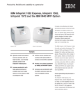
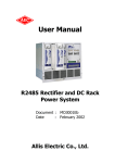
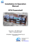
1
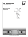
Infoprint 15x2 Depot Repair Procedure
TLI/ Part Number sequence: xxxx
Content Owner: George Maslin
Process Flow Owner: Andy Steinkuhl
CREATION DATE: 12/02/05
REVISION DATE: 07/24/06
Doc ID: USDEPOTDOC29
IBM Infoprint 1532, 1552 and 1572
Printer Descriptions:
Model name
Machine type
Infoprint 1532n
4536-n01
Infoprint 1552
4537-001
Infoprint 1552n
4537-n01
Infoprint 1572n
4538-n01
Parts Required:
Hi-yield Toner Cartridge
Duplex Option for 250 sheet models
Duplex Option for 500 sheet models
3 - 500 Sheet Drawers
75P6961
Tools Required:
453x service manual
Flat-blade screwdrivers of various sizes
Phillips screwdrivers of various sizes
7.0 mm nut driver
5.5 mm wrench
Needlenose pliers
Spring hook
Analog or digital multimeter
Flash light (optional, but strongly recommended)
Diagonal side cutters (optional, but recommended)
Table of Contents:
Section 01
Section 02
Section 03
Section 04
Section 05
Section 06
Section 07
Section 08
Section 09
Section 10
Determining Printer Condition and Service History
Visual Inspection
Functional Tests
Network Card Reset and Testing
RPQ/TLI Instructions
System Test and Configuration
Repair Procedure Completion Checklist
QC Checklist
Packaging
Revisions
Page 1 of 17
Infoprint 15x2 Depot Repair Procedure
TLI/ Part Number sequence: xxxx
Content Owner: George Maslin
Process Flow Owner: Andy Steinkuhl
CREATION DATE: 12/02/05
REVISION DATE: 07/24/06
Doc ID: USDEPOTDOC29
Section 01: Determining Printer Condition and Service History
1.
Compare the model and serial number of the printer with the work order in the tracking system:
If the printer...
Information matches the work order
Information does not match the work order
Then …
Continue
Set this printer to the side and notify your supervisor
of the discrepancy
2.
Scrap the printer if it has one of the following conditions:
• Frame damage.
• Excessive toner/dust contamination.
• Rodent/insect contamination.
3.
Prepare the printer for testing:
Step
A
B
C
D
4.
Action
Install a working toner cartridge.
Load tray 1 with at least 20 pages of plain letter size paper.
Attach a power cord to the printer and a grounded power source.
Move the printer’s power switch to the “ON” ( | ) position.
Does the printer go to Ready?
If the printer displays…
An error.
Ready
5.
Update the RIP and Engine code with PrinterActive:
If the update fails…
Once
Twice
6.
Then
Go to step 7
Continue testing.
Then
Try updating again
Go to step 7
Use the steps below to print the Quality Test pages:
Step
A
B
C
D
E
F
G
H
Action
Turn the printer off.
Turn the printer on while holding the Down and Right arrow buttons.
Release the buttons when “………..” appears on the LCD screen.
Press the Down menu button until “Print Tests” is checked, and press the Select button.
Press the Down menu button until “Prt Quality Pgs” is checked, and press the Select button to print.
After the 4 Quality Pages finish printing, turn the printer off and back on to return the printer to the normal operating
mode.
The 4 quality test pages will print (the last page should be blank)
Use these pages to isolate print quality problems. Refer to the Print Quality Service checks starting on page 2-88 of the
4520 service manual for diagnosis if needed.
Page 2 of 17
Infoprint 15x2 Depot Repair Procedure
TLI/ Part Number sequence: xxxx
Content Owner: George Maslin
Process Flow Owner: Andy Steinkuhl
7.
Determine what parts will be needed to repair the printer.
If the parts are…
In stock
Not in stock
8.
CREATION DATE: 12/02/05
REVISION DATE: 07/24/06
Doc ID: USDEPOTDOC29
Then
Replace the parts and restart this procedure at step 3
Make sure an order for them is placed and set the printer aside Awaiting Parts.
Check the printer’s previous repair history in the tracking system.
If the printer has been…
Serviced more than once
Serviced more than once
Never been serviced
and
For the same
problem
Not for the
same problem
N/A
Then
Use the previous complaint, fix and the error log on the first Quality Page
(Figure B) as a guide in the current repair
Use the error log on the first Quality Page (Figure B) as a guide in the current
repair.
Use the error log on the first Quality Page (Figure B) as a guide in the current
repair.
Section 02: Visual Inspection | toc
1.
2.
3.
4.
Clean printers with toner/dust contamination by removing the top, left and right covers and use compressed air and/or a
toner vacuum. Avoid contaminating the printhead with dust.
Check all covers for damage. All covers must meet the A, B, and C surface cosmetics requirements.
Check the operator panel, buttons and printed text for damage.
Check the UL label (pictured below) on the back of the printer for damage.
5.
6.
Open the front cover.
Check the TLI/Serial number label on the left for damage.
7.
Clean the interior of the printer, as needed.
Page 3 of 17
Infoprint 15x2 Depot Repair Procedure
TLI/ Part Number sequence: xxxx
Content Owner: George Maslin
Process Flow Owner: Andy Steinkuhl
8.
CREATION DATE: 12/02/05
REVISION DATE: 07/24/06
Doc ID: USDEPOTDOC29
Remove the charge rollers (pictured below):
a. Check the charge rollers for damage..
b. Make sure the brass colored bearing is in place on the right side.
c. Re-install the charge roller and make sure it is installed correctly.
9.
Remove the transfer roller and clean the area with a toner vac.
a. Check the transfer roller (pictured below) for damage or wear.
10. Check the inner deflector and fuser input guide (pictured below) for damage or contamination.
Page 4 of 17
Infoprint 15x2 Depot Repair Procedure
TLI/ Part Number sequence: xxxx
Content Owner: George Maslin
Process Flow Owner: Andy Steinkuhl
CREATION DATE: 12/02/05
REVISION DATE: 07/24/06
Doc ID: USDEPOTDOC29
11. Check the paper feed alignment assembly rollers (circled below) for damage or contamination.
12. Check the input flag (circled below) for damage.
13. Check the toner sensor (circled below) for damage or obstructions.
14. Check the 4 HVPS contacts (pictured below) on the inside right for damage. Make sure the contacts are clean and spring
back when pressed.
Page 5 of 17
Infoprint 15x2 Depot Repair Procedure
TLI/ Part Number sequence: xxxx
Content Owner: George Maslin
Process Flow Owner: Andy Steinkuhl
CREATION DATE: 12/02/05
REVISION DATE: 07/24/06
Doc ID: USDEPOTDOC29
15. Check the cartridge detents (circled below) for damage.
16. Check the upper paper feed deflector (pictured below left) and multipurpose feeder paper flag (pictured below right).
a. Remove the upper paper feed deflector and check the paper path for adhesive, paper or obstructions.
17. Check the ESD shield for the envelope feeder and the connector plug under shield for damage.
18. Check the lower front cover (multipurpose feeder door) paper extender and grey release lever.
Page 6 of 17
Infoprint 15x2 Depot Repair Procedure
TLI/ Part Number sequence: xxxx
Content Owner: George Maslin
Process Flow Owner: Andy Steinkuhl
CREATION DATE: 12/02/05
REVISION DATE: 07/24/06
Doc ID: USDEPOTDOC29
19. Remove the paper tray.
a. Make sure the green paper size guides on the tray function properly.
b. Make sure the black paper separation guides (circled in red below) are present and undamaged.
20. Check the paper size tabs (circled below) on the left side of the tray. Make sure none are loose, broken, damaged, or
missing.
21. Flip the paper tray over and check the connection between the tray length guide and the auto size slider on the underside
of the tray. Make sure these two plastic pieces are connected.
Page 7 of 17
Infoprint 15x2 Depot Repair Procedure
TLI/ Part Number sequence: xxxx
Content Owner: George Maslin
Process Flow Owner: Andy Steinkuhl
CREATION DATE: 12/02/05
REVISION DATE: 07/24/06
Doc ID: USDEPOTDOC29
22. Gently lay the printer on its back , so the bottom of the printer can be viewed.
a. Make sure the four belly band screws are not loose
b. Check the 4 rubber feet for damage.
c. Check the Auto-connect plug for damage.
d. Check the Tray Bias Arm and spring for damage. The tray bias arm should spring back when pressed.
e. Check the auto compensator bell crank arm and spring for damage.
f. Check the PTO shaft for damage. Press on the PTO shaft, and it should spring back when released.
g. Check the Auto-compensator wiring for damage, and make sure they are routed correctly.
h. Push the redrive/duplex actuator arm. The arm should move freely with very little resistance. If the actuator arm does
not move freely, remove the redrive assembly to identify the cause.
i. Replace the Pick Rollers regardless of condition.
23. Check the condition of the auto size fingers (circled below). Make sure none are bent or missing.
24. Return the printer to the upright position and re-install the paper tray.
25. Remove the left side cover.
Page 8 of 17
Infoprint 15x2 Depot Repair Procedure
TLI/ Part Number sequence: xxxx
Content Owner: George Maslin
Process Flow Owner: Andy Steinkuhl
CREATION DATE: 12/02/05
REVISION DATE: 07/24/06
Doc ID: USDEPOTDOC29
26. Check the Printhead Cable:
Step
1
Action
Loosen the screws securing the ESD shield
on the System Board and remove the shield.
2
Locate the printhead cable at position J2 on
the board.
3
Determine if there is a Toroid (black metallic
cylinder) on the printhead cable.
Image
4
If there …
Is a Toroid on the
Printhead cable.
Is no Toroid
5
6
Then
It must be tied to
the System Board
cage.
No action is needed
Clean the system board area and make sure
any options are fully seated.
Reinstall the ESD shield and tighten the
screws securing it to the printer.
Page 9 of 17
Infoprint 15x2 Depot Repair Procedure
TLI/ Part Number sequence: xxxx
Content Owner: George Maslin
Process Flow Owner: Andy Steinkuhl
CREATION DATE: 12/02/05
REVISION DATE: 07/24/06
Doc ID: USDEPOTDOC29
27. Remove the white plastic gear guard (pictured below left).
a. The teeth on the bevel gear (pictured above right) should be undamaged and properly greased.
b. Grab the bevel gear and gently try moving the gear up and down to see how much play is there. There should be very
little, if there is signifigant play the bevel gear should be replaced.
28. Remove the redrive cap from the top of the printer (if not already removed).
29. Check the exit/bin full flag (circled below left).
30. Check the autoconnect (above right) on the top of the printer for damage.
31. Rotate the printer in order to access the back.
32. From the rear of the printer, inspect the left side of the redrive assembly where the exit rollers are attached. Make sure the
rollers are snapped in completely and that there is no damage in this area
33. Remove the outer redrive door.
34. Check the paper diverter assembly (pictured below left) and ribs on the door for any contamination or damage.
Also, make sure the spring (above right) on the diverter is installed and working properly.
35. Confirm that the upper diverter guide and spring are installed and working correctly.
Page 10 of 17
Infoprint 15x2 Depot Repair Procedure
TLI/ Part Number sequence: xxxx
Content Owner: George Maslin
Process Flow Owner: Andy Steinkuhl
CREATION DATE: 12/02/05
REVISION DATE: 07/24/06
Doc ID: USDEPOTDOC29
Section 03: Functional Tests | toc
1.
Enter Diagnostics mode:
2.
Check the print Registration (skew): Note: Make sure the paper guides in the tray are set properly before making any
registration changes.
a. Select Quick test in the registration menu, and make adjustments as needed.
b. Keep the final registration page with the printer paper work for QC verification.
3.
Print the Event Log:
a. Select the Event Log menu.
b. Select Print Log.
c. Look through the events detailed on these pages and keep these in mind while repairing the printer.
d. Keep these pages with the printer for QC verification.
e. Select Clear Log and select Yes.
4.
In the Print Tests menu, perform a continuous print test for the following:
a. 30 pages from the Multipurpose feeder.
b. Keep one page with the printer for QC verification (write MP feeder test on the page)
c. 60 pages from Tray 1.
d. Keep one page with the printer for QC verification (write Tray 1 test on the page)
5.
Printers with a Parallel port:
a. Attach a parallel cable to the printer.
b. Open the Parallel Port Test Pages shortcut on the PC desktop.
c. Click on File and Print to run the test pages.
d. Keep page #1 and #35 with the printer for QC verification.
Page 11 of 17
Infoprint 15x2 Depot Repair Procedure
TLI/ Part Number sequence: xxxx
Content Owner: George Maslin
Process Flow Owner: Andy Steinkuhl
6.
CREATION DATE: 12/02/05
REVISION DATE: 07/24/06
Doc ID: USDEPOTDOC29
Perform the Duplex Quick Test.
• Print 15 copies of the duplex test.
• Keep one page with the printer for QC verification (write Duplex test on the page)
7. Perform the printer Hardware Tests, but only run the following:
a. LCD test
b. Button test
8. Resetting the Maintenance Count:
If the page count is ... and the …
Low
Fuser is being replaced
Low
Fuser condition is OK
125,000 – 150,000
Fuser is being replaced
125,000 – 150,000
Fuser condition is OK
High
Fuser is being replaced
High
Fuser condition is OK
Then ...
Reset the Maintenance Count
Reset the Maintenance Count
Reset the Maintenance Count
Reset the Maintenance Count
Reset the Maintenance Count
Research the printer’s service history:
If the fuser …
Was replaced
previously
Was not replaced
Then …
Reset the Maintenance
Count
Replace the fuser and
reset the Maintenance
Count
9. Turn the printer off and back on or select Exit Diagnostics to return the printer to a normal operating state.
Section 04: Network Card Reset and Testing | toc
1. Enter Configuration Menu:
2.
3.
4.
5.
6.
7.
8.
9.
Once the printer has finished warm up “CONFIG MENU” will appear on the display.
Press the down arrow button until “Factory Defaults” is displayed.
Press the Select button.
Press the up or down arrow to select “Restore Network”.
Press the Select button.
The printer will reset to a Ready state once the defaults have been restored.
Print the Network Setup page from the Reports menu.
On the page that prints verify the following:
a. Status = Not Connected
b. Active = Yes
c. DHCP,BOOTP,RARP Enabled = Yes, Yes, Yes
d. Address Source = Manual
e. Address = 0.0.0.0
Page 12 of 17
Infoprint 15x2 Depot Repair Procedure
TLI/ Part Number sequence: xxxx
Content Owner: George Maslin
Process Flow Owner: Andy Steinkuhl
CREATION DATE: 12/02/05
REVISION DATE: 07/24/06
Doc ID: USDEPOTDOC29
10. Plug the network cable into the printer.
11. The printer should automatically acquire an IP address and print a network settings page.
12. Locate the IP address on the network page (pictured below, which inidcates successful network communication).
13. Disconnect the network cable.
14. Access the Configuration Menu:
a. Turn the printer off
b. Press and hold the Select and the Return buttons while turning the printer on
c. Release the buttons when “Performing Self Test” appears on the LCD
d. “CONFIG MENU” will appear on the LCD once warm up is complete
15.
16.
17.
18.
Press the right Menu button to reach “Factory Defaults” and press the Select button.
Press the right Menu button to reach “Factory Defaults=Restore Network” and press Select button again.
The printer will return to the Ready state once the defaults have been restored.
Print the network setup page:
a. Press the right Menu button on the printer’s operator panel to reach the Utilities menu
b. Press the Select button
c. Press the Right menu button to reach “Print Net Setup”
d. Press the Select button to print the page.
19. On the page that prints verify the following:
• Status = Not Connected
• Active = Yes
• DHCP,BOOTP,RARP Enabled = Yes, Yes, Yes
• Address Source = Manual
• Address = 0.0.0.0
• Keep this page with the printer for QC verification.
Section 05: System Test and Configuration | toc
1.
2.
3.
Connect to the WinCSU stand alone system (or CSU Network System Printer Active, if available) through the USB port.
Double-click on CSU icon on the desktop to load the test program.
Click Change Top Bill -> Browse -> TLI Masters -> 15x2 then select the TLI number matching with the printer (TLI
number can be found by opening the front cover). Click OK.
4. In WinCSU-Seclect TLI, make sure the TLI number is correct, then click OK.
5. Click CSU test, then click Start.
6. Enter the TLI number, then click OK.
7. Enter the serial number, then click OK.
8. Load manual MPFEEDER with letter paper. Click Pass.
9. Review print samples. Verify there are no:
• Light or blurred characters
• Toner smudges on the front or back
• Vertical Streaks
• Smears or ruboffs
• Indicate if Print Test passed.
• Keep the printouts with the printer for QC verification.
10. Wait for the test to complete.
11. Verify all parts of the test pass.
12. Verify exterior of the printer is clean.
Page 13 of 17
Infoprint 15x2 Depot Repair Procedure
TLI/ Part Number sequence: xxxx
Content Owner: George Maslin
Process Flow Owner: Andy Steinkuhl
CREATION DATE: 12/02/05
REVISION DATE: 07/24/06
Doc ID: USDEPOTDOC29
Section 06: Repair Procedure Completion Checklist
1.____ Firmware OK
2.____ Covers are OK & clean.
3.____ Operator panel is OK
4.____ UL label is OK
5.____ TLI label is OK
6.____ Inside clean
7.____ Charge roller is OK
8.____ Transfer roller OK
9.____ Input guides are OK
10.____ Paper feed alignment is OK
11.____ Input flag is OK
12.____ Toner sensor is OK
13.____ HVPS contacts are OK
14.____ Door hinges are OK
15.____ Cartridge detents are OK
16.____ Tray is OK
17.____ Bottom OK (4 feet, auto-connect, bellcrank & auto-comp)
18.____ Pick rollers replaced
19.____ PTO shaft and Bevel gear are OK
20.____ Redrive is OK
21.____ Registration OK
22.____ Quality pages OK
23.____ Error log cleared
24.____ Paper feeds OK
25.____ Duplex test OK
26.____ MP feeder test OK
27.____ Tray 1 test OK
28.____ Parallel test is OK (if applicable)
29.____ Maintenance count has been reset.
Page 14 of 17
Infoprint 15x2 Depot Repair Procedure
TLI/ Part Number sequence: xxxx
Content Owner: George Maslin
Process Flow Owner: Andy Steinkuhl
CREATION DATE: 12/02/05
REVISION DATE: 07/24/06
Doc ID: USDEPOTDOC29
Section 07: QC Checklist
1. Test pages from repair process are present:
• ____ Menu settings page
• ____ Network settings page (when applicable)
• ____ Registration page
• ____ MP feeder test page
• ____ Tray 1 test page
• ____ #1 and #35 Parallel test pages
• ____ Duplex test page
• ____ Quality test pages
• ____ WinCSU pages
• ____ Windows test page
• ____ Print server settings pages (when applicable)
2.
3.
4.
5.
____Serial number on the paper work matches the printer.
____Covers are clean and undamaged
____Operator panel is OK
____UL label on back is OK
6. Ports and clips are ok.
• ____Parallel clips are present.
• ____Ethernet port will hold a cable.
• ____ USB port is OK
7.
8.
9.
10.
____Inside of printer is clean (no dust or toner)
____Transfer roller OK.
____Charge rollers OK.
____Hi-volt contacts OK
11. Print the Menu settings page:
a. ____ Printer name is T64x at the top of the page.
b. ____Serial number on pages matches printer.
c. ____Network models, Network settings page printed and the TCP/IP settings have been reset (highlighted
below)
12. Print the Quality test pages:
a. ____Quality pages print and print quality is acceptable.
13. ____Clean interior of printer as needed
14. ____Remove and file paperwork
Page 15 of 17
Infoprint 15x2 Depot Repair Procedure
TLI/ Part Number sequence: xxxx
Content Owner: George Maslin
Process Flow Owner: Andy Steinkuhl
CREATION DATE: 12/02/05
REVISION DATE: 07/24/06
Doc ID: USDEPOTDOC29
Section 08: Packaging | toc
Page 16 of 17
Infoprint 15x2 Depot Repair Procedure
TLI/ Part Number sequence: xxxx
Content Owner: George Maslin
Process Flow Owner: Andy Steinkuhl
CREATION DATE: 12/02/05
REVISION DATE: 07/24/06
Doc ID: USDEPOTDOC29
Section 09: Revisions
Revision Date
12/02/05
01/11/06
02/14/06
05/02/06
05/23/06
06/06/06
07/24/06
Revision Detail
Acquired Lexmark document for IBM counterpart
Added a picture of the printer to page 1
Updated the # of test pages needed for the functional test.
Added maintenance count reset to section 3 & 7, added parallel test to sec. 3
Added packaging images
Added steps to sect. 2 for checking the toroid on the printhead cable
Updated packaging images
Page 17 of 17
Revised by
Michael Trinler
Michael Trinler
Michael Trinler
Michael Trinler
Michael Trinler
Michael Trinler
Michael Trinler