1
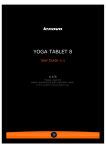
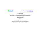
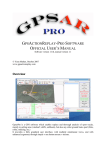
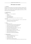
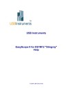
www.instrumentsolutions.com.au
ARTIFICIAL INTELLIGENCE
TEMPERATURE CONTROLLER
AI-208 (V7.6)
User Manual
www.instrumentsolutions.com.au
I. Model Code Symbol
The type of AI-208 is made up of 4 parts:
AI-208
A
G
L2
Part 1 (Series)
Part 2 (Size)
Part 3 (Oupt)
Part 4 (AUX)
1. (Part 1) Model Series
AI-208, standard temperature controller , 0.3%FS±1℃ accuracy.
Multiple thermocouples and RTDs are selectable
Suitable for 0~999℃ application. Maximum support two alarms contact output
Universal voltage input (100~240VAC)
2. (Part 2) Front panel dimension
Front Panel
Cut Out
width×height
width×height
A
96×96mm
92×92mm
100mm
B
160×80mm
152×76mm
100mm
D
72×72mm
68×68mm
95mm
D2
48×48mm
45×45mm
95mm
E
48×96mm
45×92mm
100mm
F
96×48mm
92×45mm
100mm
Size
Depth Behind Mounting Surface
www.instrumentsolutions.com.au
3. (Part 3 and 4) indicate the module installed in OUTP and AUX sockets.
Allowed modules in each socket are as below:
Allowed Type
N
L
L1
L5
G
Module Socket
√
3. OUTP (main output)
√
4. AUX (Auxiliary output)
√
√
√
N
(or none) no module installed
L
Relay contact output module (Capacity: 5A/250VAC, normal open)
L1
Relay contact output module (Capacity: 2A/250VAC, normal open/ normal close)
L5
Dual relay output module Output module (Capacity: 2A/250VAC, normal open, support AU1 and
AU2 alarm output)
G
SSR voltage output module (30mA/5VDC)
II. TECHNICAL SPECIFICATION
1. Input type :
Thermocouple: K, E, J, N
Resistance temperature detector: Pt100
2. Instrument Input range :
K, E, J, N : (0~+999)℃ ;
Pt100: (0~+800)℃
3. Measurement accuracy : 0.3%FS±1℃
4. Temperature display resolution : 0 or 0.0 (0.0 just for 0~99.9 display)
5. Control mode:
On-off control mode, or
PID control with the function of parameter auto tuning.
6. Alarm function: High limit alarm, Lower limit alarm, Deviation High Alarm; providing the function of
alarm blocking at the beginning of power on.
7. Power supply voltage rating: 100-240VAC, -15%, +10% / 50-60Hz.
8. Power consumption: ≤2W
9. Ambient temperature: -10~+60℃, Humidity: 0~90RH%
www.instrumentsolutions.com.au
III. FRONT PANEL AND OPERATION
①
Process Value(PV), or parameter code
②
Set Value(SV), alarming code, or value of a parameter
③
Setup key, for accessing parameter table, and confirming change.
④
Data shift key, also for activating auto turning
⑤
Data decrease key
⑥
Data increase key
⑦
Status display LED,
OP1, AU1, AU2, and RUN indicate I/O operation of the
corresponding module.
Basal display status:
When power on, will shows the process value (PV) and the set point (SV). lf the input signal is out of the measurable range (for example,
the thermocouple or RTD circuit is break, or input specification sets wrong). Instrument will alternately display “orA”, and limit alarm of PV,
moreover, instrument will automatically stop the output.
IV. OPERATION DESCRIPTION
●
Set Value Setting:
In basal display status, if the parameter lock “Loc” isn't locked,
key to decrease the value,
pressing
SPH.
●
or
we can set setpoint (SV) by pressing
key to increase the value, and
.
Press
key to move to the digit expected to modify.
Keep
, the speed of decreasing or inscreasing value get quick.
、
or
The range of setpoint is between the parameter
The default range is 0 to 400.
Parameter Setting:
In basal display status, press
and hold for about 2 seconds can access Field Parameter Table.
next parameter; if parameter have not locked, pressing
return to the preceding parameter. Press
、
or
Pressing
can modify a parameter.
(don't release) and then press
can go to the
Press and hold
parameter table. The instrument will escape auomatically from the parameter table if no key is pressed within 30 seconds.
Loc=808 and then press
●
can
key simultaneously can escape from the
Setting
can access System Parameter Table.
AI artificial intelligence control and auto tuning
When AI artificial intelligence control method is chosen (CrL=AI), the PID parameters can be obtained by running auto-tuning.
basal display status, press
to “on”, then press
for 2 seconds, the “At” parameter will appear.
to active the auto-tuning process.
Press
During auto tuning, the instrument executes on-off control.
times of on-off action, the instrument will obtain the optimal control parameter value.
press and hold the
In
to change the value of “At” from “oFF”
After 2-3
If you want to escape from auto tuning status,
key for about 2 seconds until the "At" parameter appear again.
Change “At” from “on” to “oFF”, press
to
confirm, then the auto tuning process will be cancelled.
Note 1:
If the setpoint is different, the parameters obtained from auto-tuning are possible different.
often-used value or middle value first, and then start auto-tuning.
be set at the highest applicable temperature.
So you’d better set setpoint to an
For the ovens with good heat preservation, the setpoint can
Depending on the system, the auto-tuning time can be from several seconds to
several hours.
Note 2:
Parameter Ctl (on-off differential, control hysteresis) has influence on the accuracy of auto-tuning.
value of Ctl, the higher the precision of auto tuning.
from error action around setpoint due to the oscillation of input.
Note 3:
Generally, the smaller the
But Ctl parameter value should be large enough to prevent the instrument
AI series instrument has the function of self-learning.
Ctl is recommended to be 2.0.
It is able to learn the process while working.
The control effect at the
first run after auto tuning is probably not perfect, but excellent control result will be obtained after a period of time because of
self-learning.
www.instrumentsolutions.com.au
V. PARAMETER AND SETTING
Field parameter table (Press
Code
Name
HIA
High limit alarm
LoA
Lower limit alarm
HdA
Deviation high
alarm
Loc
Parameter lock
AHY
Hysteresis
and hold for 2 seconds to access)
Description
Alarm on when PV (Process Value) >HIA;
alarm off when PV<HIA-AHY
Alarm on when PV (Process Value) < LoA;
alarm off when PV > LoA+AHY
Alarm on when PV-SV>HdA;
alarm off when PV-SV<HdA-AHY
Loc=0~1: Allowed to modify parameters HIA, LoA, HdA and SV.
Loc=2~3: Allowed to modify parameters HIA, LoA, HdA. But cannot
change SV.
Loc=4~255: NOT allowed to modify any parameters and SV.
Loc=808, Set to 808 and press
, allowed modify all parameters.
Avoid frequent alarm on-off action because of the fluctuation of PV,
usually sets to AHY=2
Alarm
HdA
LoA
HIA
(x100)
(x10)
(x1)
None
0
0
0
AU1
1
1
1
AU2
2
2
2
Output to
AOP
Alarm output
assignment
Setting Range
0~999℃
0~999℃
0~999℃
0~255
0~200
0~444
eg: AOP=201 means HdA have alarm action from AU2, LoA, no alarm
action , HIA alarm action output from AU1.
z
CrL
Control mode
z
onF : On-off control, When PV=SV, Output stop. When
PV<SV-CHY, start output.
AI : AI PID control, high precision and the output time proportion
can set by parameter Ctl
rE: Reverse acting. Increase in measured variable causes a decrease
in the output, such as heating control.
dr: Direct acting. Increase in measured variable causes an increase in
Act
Acting method
the output, such as refrigerating control.
rEb: Reverse acting with low limit alarm and deviation low alarm
rE , dr ,
rEb, drb
blocking at the beginning of power on.
drb: Direct acting with high limit alarm and deviation high alarm
blocking at the beginning of power on.
P
Proportion band
Proportion band in PID with unit ℃or ℉
I
Time of integral
Time of integral in PID. No integral effect when I=0
0~999 Sec
d
Time of
derivative
Time of derivative in PID. No derivative effect when d=0
0~999 Sec
Ctl
Control period
CHY
Control
hysteresis
Small value can improve control accuracy.
For SSR output, generally 0.5 to 3 seconds.
For Relay output, generally 15 to 40 seconds, because small value will
cause the frequent On-Off of mechanical switch and shorten its service
life. Ctl is recommended to be 1/4 – 1/10 of derivative time. When
control under on-off control, Ctl use as restart delay time after off, for
protect compressor application.
CHY is used for ON-OFF Control.
PV > SV, Output turns OFF;
PV<SV-CHY, Output turns ON.
1~999
0.5-300 SEC
0~200
www.instrumentsolutions.com.au
Sn
0
4
6
8-20
Input spec.
K
E
Spare
Spare
Sn
1-3
5
7
21
Input spec.
Spare
J
N
Pt100
InP
Input
specification
dPt
Resolution
0 or 0.0 selectable, 0.0 just for 0~99.9 ℃ / ℉ display
Scb
Input shift
Scb is used to make input shift to compensate the error produced by
sensor or input signal.
PV after compensation= PV before compensation + Scb.
-99~+99℃
FIL
PV input filter
The value of FIL will determine the ability of filtering noise.
When a large value is set, the measurement input is stabilized but the
response speed is slow. Generally, it can be set to 1 to 3.
If great interference exists, then you can increase parameter “FIL”
gradually to make momentary fluctuation of measured value less than
2 to 5.
When the instrument is being metrological verified, “FIL” s can be set
to 0 or 1 to shorten the response time.
0~40
Fru
Selection of
power frequency
and temperature
scale
0~21
50C: 50Hz, ℃
50F: 50Hz, ℉
60C: 60Hz, ℃
60F: 60Hz, ℉
SPH
Upper limit of SV
Maximum value that SV allowed to be. When SPH=400, the SV range
will 0~400℃
VI. INSTRUMENT INSTALLATION AND WIRING
Wiring graph for instruments with dimension A, B, E or F
1
100-240VAC~
2
3
Alarm Output
4
N/O
N/O
AU1
N/C
N/O
AU2
COM
COM
5
6
Main Output
AUX
+
N/O
COM
7
Note: The graph suits for
upright instruments with
dimension A or E
OUTP
8
9
10
+
For
instruments
with
dimension B or F size, just
clockwise rotate the graph
90 degree.
0~999℃
www.instrumentsolutions.com.au
Wiring graph for D2 dimension(48X48mm)instruments:
Wiring graph for D dimension (72mm X 72mm) instruments