Download KIP 2300 User Manual - KIP
Transcript
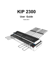
KIP 2300 User Manual
Version A.1
We highly appreciate your purchasing our KIP 2300 Image Scanner.
This User's Manual contains functional and operational explanation for KIP 2300 Image Scanner.
Read this User's Manual carefully before use in order to understand the KIP 2300 Image Scanner
completely and to use more efficiently.
Keep this User's Manual for future reference.
1. For U.S.A.
This device complies with part 15 of the FCC Rules. Operation is subject to the following two
conditions: (1) This device may not cause harmful interference, and (2) this device must accept
any interference received, including interference that may cause undesired operation.
2. For Europe
This equipment complies with the requirements in Pub.22 of CISPR Rules for a Class B
computing device.
Operation of this equipment in a residential area may cause unacceptable interference to radio
and TV reception requiring the operator to take whatever steps are necessary to correct the
interference.
Do not install Machine around electronics equipment or precision instruments.
It may be influenced by electrical reason or vibration while operation.
If Machine is installed near electronics equipment, such as TV or radio, interference to
equipment, such as noise or flickering may be occurred.
Use separate power line and install Machine as far as such equipment.
As an ENERGY STAR ® Partner, Katsuragawa Electric Co., Ltd. has determined
that this product meets the ENERGY STAR ® guidelines for energy efficiency.
The International ENERGY STAR ® Office Equipment Program is an international program that
promotes energy saving through the penetration of energy efficient computers and other office
equipment. The program backs the development and dissemination of products with functions that
effectively reduce energy consumption. It is an open system in which business proprietors can
participate voluntarily. The targeted products are office equipment such as computers, monitors,
printers, facsimiles, copiers, scanners, and multifunction devices. Their standards and logos are
uniform among participating nations.
The symbol shown indicates that this product conforms to Directive
2002/96/EC of the European Parliament and the council of 27 January
2003 on waste electrical and electronic equipment (WEEE) and does not
apply to countries outside of EU.
The symbol shown indicates that this product conforms to
SJ/T11364-2006 of People’s Republic of China Electronic
Industry Standard and does not apply to countries outside of
People’s Republic of China.
The symbol shown indicates that this product conforms to GB
18455-2001 11364-2006 of National Standard of the People’s
Republic of China and does not apply to countries outside of
People’s Republic of China.
1
WARNING FOR THE SAFETY (OBSERVE THESE WARNING)
Following warnings are very important to use this equipment safely and to prevent the operator
from danger and his/her property from being damaged.
Hazardous or damage degree is classified and shown as follows when this machine is erroneously
used ignoring this USER'S MANUAL.
WARNING
This caution mark denotes that the failure to follow given instructions in
handling the machine could result in a death or serious injury.
CAUTION
This caution mark denotes that the failure to follow given instructions in
handling the machine could result in an injury or physical damage only.
This symbol signifies what must not be done.
This symbol signifies General Mandatory Action.
2
WARNING
Connect the scanner and Ground with each other surely with the
grounding wire. Otherwise, it is dangerous for you if you receive an electric
shock or at the time of lightning. If the outlet does not have a Grounding
Terminal or if it is impossible to connect, call the vendor or service
professional for the installation.
1. Power source should be rated from 100V - 240V +6/-10%, 6A or
higher, and 50/60Hz.
2. It is preferable that the used power circuit is provided with a dedicated
breaker.
3. Install the machine as close as possible to the outlet.
4. When you wish to move the machine to another place, make sure to
ask your service engineer.
1. Do not use a multi-wiring connector that might raise the temperature of
the outlet abnormally and cause a fire.
2. Do not put anything heavy on the power cord. It may cause a fire or
receiving an electric shock.
3. Do not step on the power cord, and do not damage or process it. It
may also cause a fire or receiving an electric shock.
4. Do not tie the power cord or make a knot on it. It may also cause a fire
or receiving an electric shock.
5. Do not put a flower vase, a flowerpot or a water-filled glass on the top
of the machine. If the water spilt out, it may also cause a fire or
receiving an electric shock.
1. If the machine generates abnormal smell or noise, turn it off and then
disconnect the power plug from the outlet necessarily.
2. Do not handle the power plug with the wet hand positively. It may
cause to receive an electric shock.
3. Insert the power plug into the outlet completely. If the power plug is not
inserted completely, it may cause a fire.
4. Use only the attached power cord.
Make sure to catch the Plug when you unplug the machine.
Otherwise, you may break the cord and may result in a fire or receiving an
electric shock.
Do not disassemble or tamper the machine. Otherwise, it may cause a fire
or receiving an electric shock.
3
CAUTION
Do not install the machine at the following places.
1. Humidified or dusty place.
2. Unstable floor. (When the machine comes down, it may cause the
injury.)
Be careful not to catch your hand between Upper Unit and Main Unit when
you close the Upper Unit.
1. Unplug the machine before you move it to another place. Otherwise, the
power cord may be damaged and may result in a fire or receiving an
electric shock.
2. If nobody operates the scanner in the night time, make sure to turn it off
for the safety.
3. If nobody operates the machine for a long time during consecutive
holidays, make sure to turn it off for the safety.
4. Nothing should be put near the power plug so as to disconnect it quickly
anytime.
LED Safty (Safty of LED Products)
“Caution - Use of controls or adjustments or performance of procedures other than those
specified herein may result in hazardous radiation exposure”
As the LED on the Light Source PCBs (PW12130 & PW12131) are Class 2 LED singularly, it
is not allowed for using it with disassembling or converting.
Classification of LED product :
- CLASS 1 LED PRODUCT
IEC 60825-1:2001
EN 60825-1:1994 + A2:2001 + A1:2002
- Maximum class of the embedded LED : CLASS 2 (WHITE LED, Maximum power : 4.0mW)
4
POWER CORD INSTRUCTION
The installation of (or exchange to) a power plug which fits in the wall outlet of the installation location
shall be conducted in accordance with fallowing:
WARNING
Selected a power plug which meets the following criteria;
- The plug has a voltage and current rating appropriate for the product’s rating marked on its
name plate.
The plug meets regulatory requirements for the area.
The plug is provided with a grounding pin or terminal.
If the appropriate plug does not fit the wall outlet in the installation, the customer shall install an
appropriate outlet.
Connector Type:
Configuration
Standard
IEC60320:C13
Rating(minimum)
7A 250V(IEC)
7A 125V(UL)
Usually found in
Rating(minimum)
7A 250V
7A 250V
Usually found in
European countries
Korea
AS/NZS 3112
7A 250V
GB1002
GB2099.1
IRAM 2073
BS 1363
7A 250V
Australia
New Zealand
China
7A 250V
7A 250V
Argentina
British
SASO 2203
7A 250V
Saudi Arabia
BS 546A
IS-1293
SABS-1293
7A 250V
British
India
South Africa
SEV 1011
7A 250V
Switzerland
Rating(minimum)
7A 125V
Usually found in
US
Canada
(UL Listed Power Cord
Set only)
Plug Type : Model Rating 220-240V
Configuration
Standard
CEE7/7
KS C 8305
Plug Type : Model Rating 120V
Configuration
Standard
NEMA 5-15P
5
Cord Type
Standard
SVT 3X18AWG Long <2.4m
Rating(minimum)
7A 125V
Usually found in
North America
H05VV-F 3X0.75mm2
7A 250V
European
Argentina
RVV 3X0.75mm2
7A 250V
China
6
countries
Chapter 1
Before Use
1. 1
Installation Requirements
page
1- 2
1. 2
Features
1- 4
1. 3
Specifications
1- 5
1. 4
Name & Function of Each Part
1. 4. 1
Front view
1. 4. 2
Rear view
1- 7
1- 7
1- 9
1. 5
Specifications for Scan Original
1. 5. 1 Originals Prohibited from Duplication
1. 5. 2 Specifications for the scan original
1-10
1-10
1-11
1-1
Chapter 1 Before Use
1. 1
Installation Requirements
The following conditions have to be satisfied when installing the KIP2300 Scanner.
1. Satisfy the following input power condition.
Voltage
Current
Frequency
100 - 240V +6%/-10%
6A or higher
50 or 60Hz.
KIP2300 can be connected to the outlet simply so far as the voltage is within 100 - 240V.
(+6% and -10% are acceptable)
2. Connect the power plug to the grounded outlet.
3. To completely disconnect the equipment from the power source, please draw the power plug
from the outlet. The outlet must be easily accessible near the equipment.
4. The temperature must be within 10 through 32 degrees centigrade, and the humidity must be
within 20 through 80%.
5. Keep the equipment away from fire, dust and direct sunlight. If it is impossible to avoid the
direct sunlight, please pull the curtain to intercept the sunlight.
7. Keep enough space around the machine as follows.
(The following values are the least requirements. Please keep a wider space if possible.)
1600mm
(Rear side)
600mm
KIP2300
(Front side)
600mm
1000mm
(2000mm is required if the
original is thicker than 1.2mm)
1-2
Chapter 1 Before Use
Reference
Machine Noise Information Ordinance 3. GSGV January 18, 1991 :
The maximum sound pressure level is equal or less than 70dB (A) according to ISO 7779.
NOTE
1. For U.S.A.
This device complies with part 15 of the FCC Rules. Operation is subject to the
following two conditions: (1) This device may not cause harmful interference, and
(2) this device must accept any interference received, including interference that may
cause undesired operation.
2. For Europe
This equipment complies with the requirements in Pub.22 of CISPR Rules for a Class B
computing device.
Operation of this equipment in a residential area may cause unacceptable interference
to radio and TV reception requiring the operator to take whatever steps are necessary
to correct the interference.
Do not install Machine around electronics equipment or precision instruments.
It may be influenced by electrical reason or vibration while operation.
If Machine is installed near electronics equipment, such as TV or radio, interference to
equipment, such as noise or flickering may be occurred.
Use separate power line and install Machine as far as such equipment.
1-3
Chapter 1 Before Use
1. 2
Features
Large format full color image scanner
KIP2300 is a full color image scanner that provides various copy/scan operations with being
combined with KIP IPS controller. It provides the following 4 modes for scanning and copying.
- 24 bit color mode
- 8 bit gray mode
- 4 bit gray mode
- Binary (black & white) mode
Recognizable of various original widths
KIP 2300 Scanner can recognize the following kinds of standard original widths as well as any
non-standard widths ranging from 210mm to 1066.8mm (42”).
Metric standard original widths : A0, A1, A2, A3, A4, 36”
Engineering/Architecture widths : 36”, 34”, 30”, 24”, 22”, 18”, 17”, 12”, 11”, 8.5”
High resolution scanning
KIP2300 scanner’s 600dpi optical resolution allows for producing high quality scan/copy image
from various types of original image. Scan resolution can be increased or decreased between
100 and 2400dpi as required.
Acceptable of extensive original thickness
KIP2300 accepts a sheet type original as well as a board type one. The acceptable thickness
range is from 0.05mm to 16.0mm.
Dual original feeders
The lower original feeder accepts all supported thicknesses and sizes of originals. The original is
set with face down and ejected to the rear tray.
The upper original feeder accepts all sizes of sheet type original that is thinner than 1.49mm. The
original is set with face up for enabling an operator to check the image or orientation before
scanning. The original fed from the upper original feeder is ejected from the lower original feeder.
High-speed data transfer
If the HIL Card is installed onto the KIP IPS (or network PC connected with KIP2300) and
KIP2300 scanner is connected to the IPS with dual cables (USB 2.0 cable and HIL cable), the
data transfer from scanner to IPS can be accomplished much faster. (NOTE : PCI Express slot is
required for accepting HIL Card.)
1-4
Chapter 1 Before Use
1. 3
Specifications
Model
Type
Reading sensor
Optical Resolution
Range of Scan Resolution
Scan mode
Scanning method
Scan speed
Original type
Maximum reading width
Transportable original
length
Transportable original
width
Thickness of original
Placement of original
Light source
Warm up time
Memory
Operation system
Interface
Memory capacity
KIP2300 Image Scanner
Desktop scanner
3 CCD Reduction Optical System
(3 CCD of RGB 7450 pixels)
Main scanning (horizontal) direction
600dpi
Sub scanning (vertical) direction
600dpi
100 – 2400dpi
Binary mode
4 bit gray mode
8 bit gray mode
24 bit color mode
Sheet through type
Monochrome/Gray mode
100dpi : 12”/sec (lower feeder), 5”/sec (upper feeder)
600dpi : 5”/sec (lower feeder), 5”/sec (upper feeder)
2400dpi : 1.25”/sec (lower feeder), 1.25”/sec (upper feeder)
Color Mode
100dpi : 12”/sec (lower feeder), 5”/sec (upper feeder)
600dpi : 2”/sec (lower feeder), 2”/sec (upper feeder)
2400dpi : 0.5”/sec (lower feeder), 0.5”/sec (upper feeder)
Sheet type & board type
- Upper original feeder can accept 0.05-0.1mm.
- Lower original feeder can accept 0.05-16.0mm.
914.4mm (36”)
Max.
16,000mm
Min.
210mm
NOTE : 48” is the maximum length for “board type” original.
Max.
1066.8mm (42”)
Min.
210mm
Max.
16mm
Min.
0.05mm
Centered
White LED
Less than 10 seconds
256MB DDR DIMM
Windows Vista, XP & 2000
USB 2.0 : for controlling & image data transfer
HIL (High-speed Image Link) : for image data transfer
NOTE : Connected PC needs to have a PCI Express card slot for
installing the HIL Add-in Card
From 256MB (standard) to 2GB (Option)
NOTE
Specifications may change without notification.
1-5
Chapter 1 Before Use
Power source
Max. power consumption
Average power
consumption
Dimension
Weight
Environmental conditions
Acoustic noise
Option
Stacking capacity of trays
Voltage
100 - 120V +6%/-10%
200 - 240V +6%/-10%
Note : Scanner accepts any voltage so far as it is within 100-240V
+6%/-10%.
Frequency
50 or 60Hz
Less than 120W
(US : 120V)
- During scanning
- Stand by
- In Power Save Mode
120W
50W
0W
(EUR / ASIA : 200-240V)
- During scanning
120W
- Stand by
50W
- In Power Save Mode
0W
1,366mm (Width) x 543mm (Depth) x 318mm (Height)
NOTE : Original Guides, Original Tray and Pedestal are excluded.
About 76kg
Temperature
10 - 32 degrees centigrade
Humidity
15 - 85%RH (No dew)
(Recommended)
23 degrees centigrade and 60% RH (No dew)
Stand by
Less than 55db
During scanning
Less than 60db
Impulse sound
Less than 70db
Pedestal (Scanner Stand)
Front Steel Tray
- Max. number of originals : about 20 sheets of 36”x48”
- Max. weight of originals : 2.2kg/square meter
Rear Steel Tray
- Max. number of originals : about 50 sheets of 36”x48”
- Max. weight of originals : 5kg/square meter
NOTE
Specifications may change without notification.
1-6
Chapter 1 Before Use
1. 4
Name & Function of Each Part
1. 4. 1
Front view
5
6
2
1
3
11
4
6
10
5
B OA R D
7
9
8
1-7
Chapter 1 Before Use
No.
1
Name
Upper Original Feeder
5
Original Guides
6
7
Levers
Board Button & Lamp
8
Stop Button & Lamp
9
Power Lamp
10
Front Steel Tray
Function
Upper Original Feeder accepts a sheet type original that is 0.05-1.49mm in
thickness. Please set the original with face down. The original fed from here
Feeder is ejected to the front side of scanner via Lower Original Feeder.
Lower original Feeder accepts not only a sheet type original that is 0.05-1.49
in thickness, but also a board type original that is 1.5-16.0mm in thickness.
Please set the original with face down. The original fed from here is ejected to
the rear side of scanner and received by the Rear Steel Tray.
This lights green when the Upper Original Feeder can accepts original
insertion, and does not light when it can not accept.
This lights green when the Upper Original Feeder can accepts original
insertion, and does not light when it can not accept. And in the Board Original
Mode, it blinks green when the scanner detects original size.
These guides can be shifter left and right according to the original width, and
prevent the original from skewing during scanning.
Unlocking the Levers allow for opening the Scanner Upper Unit.
Pressing the Board Button enables or disables Board Original Mode. The
Board Lamp lights green when the Board Original Mode is enabled.
Pressing the Stop Button during scanning will stop scanning and original
transportation in the middle, and one more will eject the original to either front
or rear.
This shows the status of scanner.
- Blinking in green : During initialization (not ready)
- Lighting in green : Ready for scanning or during scanning
- Lighting in orange : Scanning (original transportation) is paused
- Blinking in orange : Ejecting the original
- Lighting in red : Scanner has any error
Helps feeding a board type original into the Lower Original Feeder.
2
Lower Original Feeder
3
Upper Original Feeder
Indicator
Lower Original Feeder
Indicator
Rear Steel Tray
Max. number of originals : about 20 sheets of 36”x48”
Max. weight of originals : 2.2kg/square meter
Receives the original ejected from the scanner after scanning.
4
11
Max. number of originals : about 50 sheets of 36”x48”
Max. weight of originals : 5kg/square meter
1-8
Chapter 1 Before Use
1. 4. 2
Rear view
1
2
No.
1
2
Name
Rear Counter Rollers
USB Terminal
3
HIL Terminal
4
Inlet
3
4
Function
Help to transport the original when ejected.
USB cable is connected.
- Connected to the PC
- Type B Connector
- 3.3V max
HIL Connector is connected.
- Connected to the PC
- 3.3V max
Power cord is connected.
1-9
Chapter 1 Before Use
1. 5
Specifications for Scan Original
1. 5. 1
Originals Prohibited from Duplication
It may be illegal to duplicate or copy certain types of originals and you may be punished by local or
regional laws, if copies are made of these types of originals.
Please be aware of your local or regional laws and which originals they forbid you to duplicate.
Some Examples:
[Originals prohibited from copying by the law(s)]
1. Do not copy Currency (Bill, Money, Bank Note, etc.), Government issued Negotiable
Instruments (National Bonds, Security, Local Debt Bonds, etc.).
2. Do not copy Foreign Currency or Foreign Negotiable Instruments.
3. Do not copy unused postal stamps or government postcards without permission to make
replica from said Governments.
4. Do not copy Government issued revenue stamps, certificate stamps that are prescribed by
Liquor Tax Act or the Commodity Tax Act.
[Special items which require your attention]
1. The government issues warnings if you are to copy private issued securities (stock certificate,
draft, check, goods ticket, etc.), commutation ticket or book of tickets, excluding that some
specific company copies such originals as many as it requires for its own business.
2. We recommend you not copy originals as government issued passports, public or private
issued licenses, automobile inspection certification, ID and tickets passes or meals.
[Originals protected by the copyright]
It is prohibited to copy originals such as books, music, paintings, printed copies, maps, drawings,
movie posters and pictures which are protected by the copyright laws.
Please see your local or regional laws.
1-10
Chapter 1 Before Use
1. 5. 2
Specifications for the scan original
Original’s thickness which KIP2300 scanner accepts is 0.05 through 16mm. Originals are divided
into 2 types such as sheet type and board type in terms of the thickness.
- Sheet type : 0.05 through 1.49mm
- Board type : 1.50 through 16.0mm
Sheet type original
(0.05 through 1.49mm)
Board type original
(1.50 through 16mm)
The available original size differs according to the type.
Length
Width
Weight
Sheet type
210 through 16000mm
210 through 1066.8mm
-
Board type
210 through 1219mm
210 through 914mm
2.2kg / square meter
Do not scan the following types of original as it may damage the original or scanner itself.
With stick-on label
Paste
Torn
1-11
Chapter 1 Before Use
Folded (Leading edge)
Uneven thickness
Curled
(Diameter of curl must be
larger than 80mm.)
Irregular shape (Not square)
KIP
KIP
Wet (Ink is not dried)
Wet
Made of metal or cloth
1-12
Metal
Cloth
KIP
KIP
Chapter 1 Before Use
Patched
Clipped or stapled
Rough surface
(Carbon paper for example)
Clipped
Stapled
KIP
KIP
Rough surface
Punched
Dusty
Electrically changed
Photograph
1-13
Chapter 1 Before Use
Chapter 2
Scanner Hardware Operation
2. 1
page
2- 2
Turning ON the KIP2300
2. 2
Scanning an Original
2. 2. 1 Scanning a sheet type original
(1) Using the Upper Original Feeder
(2) Using the Lower Original Feeder
2. 2. 2 Scanning a board type original
2- 4
2- 4
2- 4
2- 7
2-10
2. 3
Cancellation of Current Scan
2-18
2. 2
Turning OFF the KIP 2300
2-19
2. 5
Auto Power OFF
2-20
2. 6
Removal of Trays
2. 6. 1 Front Steel Trays
2. 6. 2 Rear Steel Trays
2-21
2-21
2-24
2-1
Chapter 2 Basic Operation
2. 1
Turning ON the KIP 2300
1. Prepare a power cable that satisfies the following specifications.
2. Connect the KIP2300 scanner to the outlet via the power cable.
WARNING
(1) Do not handle the power plug with a wet hand. It may result in receiving an electrical
shock.
(2) Ground the machine for safety.
(3) Please connect to a dedicated outlet. Many loads on a single outlet may cause
overheating and result in a fire.
(4) The outlet must satisfy 100-240V +6%/-10%, 50/60Hz, 6A or higher.
3. Turn on the KIP2300 scanner pressing the bar ( | ) side of Power Switch on the left.
Press this side for turning on.
4. Scanner takes initialization. It takes about 10 seconds for the initialization, and the scanner
does not accept original insertion during this period, which is shown by green flash of Power
Lamp.
Power Lamp (flashes before ready)
B OA R D
2-2
Chapter 2 Basic Operation
5. Scanner gets ready when all the initializations are finished, which is shown by continuous
lighting of Power Lamp in green.
Power Lamp (lights when ready)
B OA R D
2-3
Chapter 2 Basic Operation
2. 2
Scanning an Original
2. 2. 1
Scanning a sheet type original
A sheet type original can be fed from both upper and lower original feeders.
- Upper original feeder accepts 0.05 to 0.1mm in thickness.
- Lower original feeder accepts 0.05 to 1.5mm in thickness.
Upper Original Feeder
Sheet type original
(0.05 through 1.0mm)
Lower Original Feeder
(1) Using the Upper Original Feeder
The thickness of original that the upper original feeder can accept is from 0.05 to 0.1mm.
1. Confirm the Upper Original Feeder Indicator is lighting in green. The original can be accepted
only when it is lighting in green.
Upper Original Feeder Indicator
2-4
Chapter 2 Basic Operation
2. The Original Guides will prevent the original from skewing during scanning. Move them onto
the Upper Original Feeder (if on the Lower Original Feeder). Then according to the width of
scan original, align the inside edge of Original Guides to the concerning size lines on the table.
Original Guides
3. Confirm that the original is face up. Aligning both side edges with the Original Guides, insert
the scan original into the Upper Original Feeder until the leading hits the feeding roller. Wait a
few seconds with contacting the leading edge to the feeding rollers until the scanner starts
transporting.
4. A few seconds later the scanner automatically transports the original a little to the rear side to
detect its width. After that the original is moved back to the front side.
2-5
Chapter 2 Basic Operation
5. KIP2300 starts scanning automatically or manually according to the operation on the controller
software. The original is turned and ejected to the front side via Lower Original Feeder.
2-6
Chapter 2 Basic Operation
(2) Using the Lower Original Feeder
The thickness of original that the lower original feeder can accept by normal mode is from 0.05 to
1.5mm.
1. Confirm the Lower Original Feeder Indicator is lighting in green. The original can be accepted
only when it is lighting in green.
Lower Original Feeder Indicator
2. The Original Guides will prevent the original from skewing during scanning. Move them onto
the Lower Original Feeder (if on the Upper Original Feeder). Then according to the width of
scan original, align the inside edge of Original Guides to the concerning size lines on the table.
Original Guides
2-7
Chapter 2 Basic Operation
3. Confirm that the original is face down.
4. Aligning both side edges with the Original Guides, insert the scan original into the Lower
Original Feeder until the leading hits the feeding roller. Wait a few seconds with contacting the
leading edge to the feeding rollers until the scanner starts transporting.
5. A few seconds later the scanner automatically transports the original a little to the rear side to
detect its width. After that the original is moved back to the front side.
2-8
Chapter 2 Basic Operation
5. KIP2300 starts scanning automatically or manually according to the operation on the controller
software.
NOTE
The lower original feeder will transport the original very quickly especially when low scan
resolution is selected in the monochrome/gray mode. Be careful not to touch the edge of
original during transportation so as not to be harmed.
6. The original is ejected to the rear side and stacked on the Rear Steel Tray.
2-9
Chapter 2 Basic Operation
2. 2. 2
Scanning a board type original
An original thicker than 1.5mm needs to be scanned in the board original mode, and it also needs
to be fed into the Lower Original Feeder.
Board type original
(1.5 through 16.0mm)
Lower Original Feeder
1. Confirm the Lower Original Feeder Indicator is lighting in green, which means the scanner is
currently acceptable of original.
Lower Original Feeder Indicator
2-10
Chapter 2 Basic Operation
2. Move the bottom ends of Rear Steel Trays from normal position to low position, which will set
the entire Rear Steel Trays to the low (flat) position.
Normal position
Low position
Normal position
Low position
NOTE
Please set the Rear Steel Trays to the low position when a board type original is scanned.
2-11
Chapter 2 Basic Operation
3. Press BOARD Button to enable the Board Original Feeding Mode. The BOARD Lamp lights in
green, and the Power Lamp blinks in green with waiting the insertion of board original.
BOARD Lamp (lights)
B OA R D
Power Lamp (blinks)
BOARD Button
(Press this to enable the
board original mode)
4. The Document Press Unit moves up when the BOARD button is pressed, which allows for
accepting thick original by having wide space in the Lower Original Feeder.
Normal
Board Original Feeding Mode
Space for accepting a thick original
2-12
Chapter 2 Basic Operation
5. The Original Guides will prevent the original from skewing during scanning when placed
correctly. Referring to the size lines on the scanner table, place these guides to the locations
where the edges of scan original will be.
Original Guides
6. Confirm that the original is face down.
Backside
2-13
Chapter 2 Basic Operation
7. With aligning both side edges with the Original Guides, insert the scan original into the Lower
Original Feeder and move it forward until the Lower Original Feeder Indicator starts blinking,
which notices that the original is enough inserted.
Leading edge of the original
Blinks when original is enough inserted
2-14
Chapter 2 Basic Operation
8. Press the BOARD Button. The Document Press Unit moves down and holds the original
firmly.
BOARD Button
B OA R D
Document Press Unit (This moves down.)
2-15
Chapter 2 Basic Operation
CAUTION
Do not put the hand under the Document Press Unit when it is moving down as the hand will
be caught.
- Even if the hand is caught by the Document Press Unit accidentally, the scanner
automatically detects it and moves up the Document Press Unit within a few seconds
for relieving the hand.
- Or the operator can relieve his hand by
Scanner upper unit
opening the scanner upper unit with
pulling either one of blue levers.
Blue levers
9. The scanner automatically detects the width of original then moves the original to the front side
for placing it at the start position.
10. KIP2300 starts scanning automatically or manually according to the operation on the controller
software.
2-16
Chapter 2 Basic Operation
10. The original is ejected to the rear side and stacked on the Rear Steel Tray.
2-17
Chapter 2 Basic Operation
2. 3
Cancellation of Current Scan
1. Press of the Stop Button during scanning will cancel current scan, and the KIP2300 stops
original feeding.
B OA R D
Stop button
2. One more press of the Stop Button will eject the original to either front or rear accordingly to
the location of original.
NOTE
When removing a very thick board type original, do not open the scanner upper unit as the
following example. Please eject it by pressing the Stop button as instructed in the above.
Scanner upper unit
2-18
Chapter 2 Basic Operation
2. 4
Turning OFF the KIP 2300
Turn off the KIP2300 scanner pressing the bar ( | ) side of Power Switch on the left.
Press this side for turning off.
2-19
Chapter 2 Basic Operation
2. 5
Auto Power OFF
KIP 2300 has Auto Power OFF feature for energy saving purpose, which automatically switches off
the scanner when 15 minutes of inactive period has passed.
Please turn on the scanner again with the Power Switch for using the scanner again.
Power switch
2-20
Chapter 2 Basic Operation
2. 6
Removal of Trays
2. 6. 1
Front Steel Trays
The Front Steel Tray can be removed when unnecessary or for saving the space. Please do as
instructed in below.
Front Steel Tray
1. Remove 4 Front Trays (1).
1
2-21
Chapter 2 Basic Operation
2. Remove the Front Tray BKT 3 (2) by twisting as arrow (A) then moving up as arrow (B).
2
B
A
2
2
3. Pull up both blue levers (3) to open the scanner upper unit.
3
2-22
Chapter 2 Basic Operation
4. Remove the Front Tray BKT 2 (4) on the right.
4
5. Remove the Front Tray BKT 1 (5) on the left.
5
6. Close the scanner upper unit finally.
2-23
Chapter 2 Basic Operation
2. 6. 2
Rear Steel Trays
The Rear Steel Tray can be removed when unnecessary or for saving the space. Please do as
instructed in below.
Rear Steel Tray
1. Move up and remove the Rear Steel Trays (1).
1
2-24
Chapter 2 Basic Operation
Chapter 3
Troubleshooting
3. 1
Original Misfeed
3. 1 When feeding into upper original feeder
3. 2 When feeding into upper original feeder
page
3- 2
3- 2
3- 4
3. 2
3- 5
Error
3-1
Chapter 3 Troubleshooting
3. 1
Original Misfeed
When the original is mis-fed during scanning, remove it manually as instructed in below.
3. 1
When feeding into upper original feeder
1. Open the document upper cover with holding both sides.
Document upper cover
Hold here when opening the document upper cover.
2. Pull up both blue levers to open the scanner upper unit.
Blue levers
3-2
Chapter 3 Troubleshooting
3. Remove the mis-fed original.
Mis-fed original
CAUTION
Take cere not to catch your hand when closing the document upper cover or scanner upper
unit.
3-3
Chapter 3 Troubleshooting
3. 2
When feeding into lower original feeder
1. Open the scanner upper unit by pulling up the blue levers on both sides.
Blue levers
2. Remove the mis-fed original.
Mis-fed original
CAUTION
Take cere not to catch your hand when closing the scanner upper unit.
3-4
Chapter 3 Troubleshooting
3. 2
Error
The Power Lamp lights in red when the scanner has any error. See the description of error
indicated on the controller monitor, and correct the error appropriately.
B OA R D
Power Lamp
(lights in red when any error occurs.)
3-5
Chapter 3 Troubleshooting
Chapter 4
Maintenance
page
4- 2
4- 2
4- 4
4- 5
4. 1
Cleaning
4. 1. 1 Document Glass
4. 1. 2 Platen
4. 1. 2 Feed Rollers
4-1
Chapter 4 Maintenance
4. 1
Cleaning
It is recommended to clean Original Glass, Platen and Feeding Rollers once a week or as needed.
Dirt of these parts may result in the image problem or getting dirt on the scan original.
4. 1. 1
Document Glass
Open the scanner upper unit. Wipe the Document Glass with a soft cloth with a little water (or with
neutral detergent) first, and wipe it with a dry soft cloth.
Document Glass
4-2
Chapter 4 Maintenance
CAUTION
The Document Glass can be removed if the thumb screws on both sides (and the brackets)
are removed. But do not touch this screw as only the service technician is allowed for
removing the Document Glass. If the Document Glass is removed, some foreign substance
may drop into the machine, and may cause several troubles as short-circuit.
Do not touch this screw!
4-3
Chapter 4 Maintenance
4. 1. 2
Platen
Wipe the entire white part of the Platen with a soft cloth with a little water (or with neutral
detergent) first, and wipe it with a dry soft cloth.
Platen : Clean the entire white part.
4-4
Chapter 4 Maintenance
4. 1. 3
Feed Rollers
Wipe the Feed Rollers with a soft cloth with a little water (or with neutral detergent) first, and wipe it
with a dry soft cloth.
Feed Rollers
Feed Rollers
4-5
Chapter 4 Maintenance
Feed Rollers
4-6
Chapter 4 Maintenance
Feed Rollers
4-7
Chapter 4 Maintenance
Image Scanner
KIP 2300 User’s Manual
Version A.1
Published by Katsuragawa Electric Co., Ltd.
21-1 Shimomaruko 4-Chome,
Ota-ku, Tokyo 146-8585, Japan
All rights reserved.
Please note that some articles, illustrations and photographs might be partially different from the
actual machine because of the modification of machine and so on.


