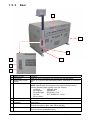
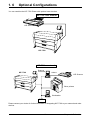
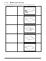
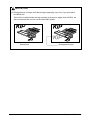
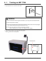
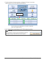
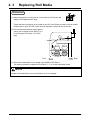
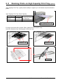
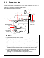
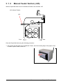
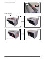
1
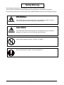
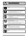
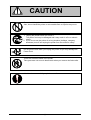
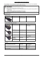
KIP 7700 User Manual
Version A1
Thank you for purchasing the KIP 7700.
This USER'S MANUAL contains functional and operational explanations for the KIP 7700.
Please read this USER'S MANUAL carefully before using the Printer.
Please keep this USER'S MANUAL for future reference.
1. When this machine is installed in North America.
FCC ID: VP8-K120
This equipment satisfies the requirements in Part 15 of FCC Rules for a Classic A computing
device. Operation is subject to the following two conditions:
(1) This device may not cause harmful interference.
(2) This device must accept any interference received, including interference that may cause
undesired operation.
In order to comply with FCC radio-frequency radiation exposure guidelines for an uncontrolled
exposure, this device and its antenna must not be co-located or operating in conjunction with
any other antenna or transmitter.
FCC 15.105(a)
NOTE: This equipment has been tested and found to comply with the limits for a Class A digital
device, pursuant to part 15 of the FCC Rules. These limits are designed to provide reasonable
protection against harmful interference when the equipment is operated in a commercial
environment. This equipment generates, uses, and can radiate radio frequency energy and, if
not installed and used in accordance with the instruction manual, may cause harmful
interference to radio communications. Operation of this equipment in a residential area is likely
to cause harmful interference in which case the user will be required to correct the interference
at his own expense.
FCC 15.21
Changes or modifications not expressly approved by the party responsible for compliance could
void the user’s authority to operate the equipment.
2. When this machine is installed in Canada
IC Company No. & UPN No. : 7391A-K120
Operation is subject to the following two conditions: (1) this device may not cause interference, and
(2) this device must accept any interference, including interference that may cause undesired
operation of the device.
3. When this machine is installed in Europe
This equipment complies with the requirements in Pub.22 of CISPR Rules for a Class B
computing device.
Operation of this equipment in a residential area may cause unacceptable interference to radio
and TV reception requiring the operator to take whatever steps are necessary to correct the
interference.
Do not install Machine around other electronic equipment or other precision instruments.
Other devices may be affected by electrical noise during operation.
If the Machine is installed near other electronic equipment, such as a TV or a radio,
interference to said equipment, such as noise or flickering, may occur.
Use a separate power line and install the PRINTER as far as possible from said equipment.
As an ENERGY STAR ® Partner, Katsuragawa Electric Co., Ltd. has determined
that this product meets the ENERGY STAR ® guidelines for energy efficiency.
The International ENERGY STAR ® Office Equipment Program is an international program that
promotes energy saving through the penetration of energy efficient computers and other office
equipment. The program backs the development and dissemination of products with functions that
effectively reduce energy consumption. It is an open system in which business proprietors can
participate voluntarily. The targeted products are office equipment such as computers, monitors,
printers, facsimiles, copiers, scanners, and multifunction devices. Their standards and logos are
uniform among participating nations.
(1)
The symbol shown indicates that this product conforms to Directive
2002/96/EC of the European Parliament and the council of 27 January
2003 on waste electrical and electronic equipment (WEEE) and does not
apply to countries outside of EU.
The symbol shown indicates that this product conforms to
SJ/T11364-2006 of People’s Republic of China Electronic
Industry Standard and does not apply to countries outside of
People’s Republic of China.
The symbol shown indicates that this product conforms to GB
18455-2001 11364-2006 of National Standard of the People’s
Republic of China and does not apply to countries outside of
People’s Republic of China.
(2)
Safety Warning
The following warnings are very important in order to safely use this product.
These notes are important in preventing danger to the operator or operation of the printer.
The following symbols are found throughout the USER’S Manual and have the following meaning:
WARNING
This WARNING mark means that there is a possibility of death or serious
injury if you ignore or do not follow the said instruction.
CAUTION
This CAUTION mark means that there is a possibility of injury or physical
damage if you ignore or do not follow the said instruction.
When marked with this symbol, “DO NOT ATTEMPT”
When marked with this symbol, “pay close attention to”
(3)
WARNING
Ground the product with a correct ground source or you may be electrically
shocked.
1. The Power source should be as follows:
220 to 240V plus 6% or minus 10%, 50/60Hz, 20A or higher
2. Use a circuit with a dedicated breaker.
3. Install the product as close to the wall outlet as possible.
4. If you wish to move the printer, please contact your service personnel.
1. Do not remove the screw and do not open the cover if not instructed to
do so in this User’s Manual. If you ignore this warning, you may be burnt
or receive an electric shock due to a hot item or electrically charged part
inside of the printer.
2. Do not disassemble or tamper with the printer.
It may result in a fire or an electrical shock.
1. Do not plug in the printer into a multi-wire connector in which some other
equipment is plugged into.
It may cause a fire due to outlet overheating.
2. Do not damage the Power Cord by stepping on or placing heavy items
on it.
If the Power Cord is damaged, it may cause a fire or you may receive
an electric shock. REPLACE THE CORD IF DAMAGED!
1. Do not put a flower vase, a flowerpot or any water-filled item on the
product.
Spilt water could cause a fire or an electric shock.
2. If the product generates an abnormal smell or noise, turn it off and
unplug it from the wall electrical outlet immediately.
Do not throw the toner into a fire or other sources of heat, as it can
explode.
(4)
CAUTION
Do not install the printer in a humidified room or a dusty room.
Also, do not install the printer on an unstable floor as injuries may occur.
1. Unplug the printer before you move it.
The power cord may be damaged and it may result in a fire or electric
shock.
2. If you do not use the printer for a long duration (holidays, company
shutdown) turn off and unplug the printer from the outlet for safety.
Do not pull the cord when you unplug the printer as you may damage the
Power Cord.
There are hot items inside of the printer.
Take great care not to touch these items when you remove mis-fed media.
Ventilate the room well if you print in a small area.
(5)
POWER CORD INSTRUCTION
The installation of (or exchange to) a power plug which fits in the wall outlet of the installation
location shall be conducted in accordance with the following:
WARNING
Select a power plug which meets the following criteria;
- The plug has a voltage and current rating appropriate for the product’s rating marked on
its name plate.
- The plug meets regulatory requirements for the area.
- The plug is provided with a grounding pin or terminal.
If the appropriate plug does not fit the wall outlet in the installation, the customer shall install an
appropriate outlet.
Connector Type:
Configuration
Standard
IEC60320:C19
Rating
20A 250V (UL)
16A 250V (IEC)
Usually found in
Rating
20A 250V
Usually found in
North America
(UL Listed)
CEE7/7
16A 250V
European countries
KS C 8305
16A 250V
Korea
AS/NZS 3112
16A 250V
Australia
New Zealand
GB1002
GB2099.1
16A 250V
China
IRAM 2073
16A 250V
Argentina
Rating
20A 250V
Usually found in
North America
(UL Listed)
HO5VV-F 3X1.5mm2
16A 250V
European countries
Argentina
RVV 3X1.5mm2
16A 250V
China
Plug Type: Model Rating 220-240V
Configuration
Standard
NEMA6-20
Cord Type
Standard
SJT 3X12AWG Long <4.5m
(6)
TABLE OF CONTENTS
Chapter 1
Before Use
1. 1
Installation Requirements
Page
1- 2
1. 2
Originals Prohibited from Duplication
1- 3
1. 3
Features
1- 4
1. 4
Specifications
1- 5
1. 5 Appearance
1. 5. 1 Front
1. 5. 2 Rear
1- 7
1- 7
1- 8
1. 6
1- 9
Optional Configurations
1. 7 Specifications for Printing Media
1. 7. 1 Available Print Size
1. 7. 2 Media not to be used
1. 7. 3 Maintaining Media
1. 7. 4 Environmental Condition - Correction
Chapter 2
1-10
1-10
1-11
1-12
1-13
Basic Operations
2. 1
Turning on KIP 7700
Page
2- 2
2. 2
Turning off KIP 7700
2- 4
2. 3
Replacing Roll Media
2- 5
2. 4
Replacing Toner Cartridge
2-13
2. 5
Placing Cut Sheet Media
2-17
2. 6
Canceling Sleep Mode
2-18
2. 7
Dehumidifying Roll Media
2-19
2. 8
Stacking Prints on High Capacity Print Tray (option)
2-21
Chapter 3
Error Corrections
3. 1 Paper Jam
3. 1. 1 Roll Deck Section (J-01, J-02, J-03, J-04)
3. 1. 2 Manual Feeder Section (J-05)
3. 1. 3 Paper Feeder Section (J-10, J-11, J-12)
3. 1. 4 Fuser Section (J-13, J-14)
3. 1. 5 Outer Device (J-21, J-22)
Page
3- 2
3- 3
3- 5
3- 6
3- 9
3-16
3. 2 Open Cover Errors
3. 2. 1 Roll Deck Open
3-17
3-17
(7)
3. 2. 2
3. 2. 3
Upper Frame Unit / Top Cover Open
Exit Cover Open
3-18
3-19
3. 3 Other Errors
3. 3. 1 Roll Replacement
3. 3. 2 Toner Empty
3-20
3-20
3-20
3. 4
3-21
Call Service Errors
(8)
Chapter 1
Before Use
1. 1
Installation Requirements
page
1- 2
1. 2
Originals Prohibited from Duplication
1- 3
1. 3
Features
1- 4
1. 4
Specifications
1- 5
1. 5 Appearance
1. 5. 1 Front
1. 5. 2 Rear
1- 7
1- 7
1- 8
1. 6
1- 9
Optional Configurations
1. 7 Specifications for Printing Media
1. 7. 1 Available Print Size
1. 7. 2 Media not to be used
1. 7. 3 Maintaining Media
1. 7. 4 Environmental Condition - Correction
1-1
1-10
1-10
1-11
1-12
1-13
Chapter 1 Before Use
1. 1
Installation Requirements
The following conditions are required for installation of the equipment.
1. Power source should be rated as follows.
220V - 240V plus 6% or minus 10%, 50/60Hz, 20A or higher
2. The equipment must be on an exclusive circuit.
3. The outlet must be near the equipment and easily accessible.
1. Make sure to connect this equipment to a grounded outlet.
2. For PLUGGABLE EQUIPMENT, the socket-outlet shall be installed near
the equipment and shall be easily accessible.
The site temperature range = 10 to 32 degrees Centigrade, with the humidity between
15% to 85% RH. (NON CONDENSING)
Keep the printer away from water sources, boilers, humidifiers or refrigerators.
1. The installation site must not have open flames, dust or ammonia gases.
2. The equipment must not be exposed to the air vents from air conditioners.
It may affect the image quality.
3. The equipment should not be exposed to the direct sunlight.
Please draw curtains to block any sunlight.
When you open the Movable Unit, do not expose the Photoconductive Drum
to strong (intense) light as this will damage the Drum.
Ozone will be generated while this equipment is use, although the quantity generated
is within safe levels. (see certifications)
Ventilate the room, if required.
Keep ample room around the equipment to ensure comfortable operation.
(Refer to the following figure.)
The equipment must be levelled and the floor strength must be ample to sustain the
weight of the equipment.
80cm or wider
45cm
or
wider
120cm or wider
Printer
80cm or wider
1-2
Chapter 1 Before Use
1. 2
Originals Prohibited from Duplication
It is not necessarily allowed to copy every kind of original.
You may be punished by the law if only you possess the copy of some kind of original.
We recommend you to consider enough before you copy such original.
[Originals prohibited from copying by the law]
1. It is not allowed to copy Currency (Bill, Money, Bank Note, etc.), Government issued
Negotiable Instruments (National Bonds, Security, Local Debt Bonds, etc.).
2. It is not allowed to copy Foreign Currency or Foreign Negotiable Instruments.
3. It is not allowed to copy unused postal stamps or government postcards without permission
to make replica from Government.
4. It is not allowed to copy Government issued revenue stamps, certificate stamps which are
prescribed by Liquor Tax Act or the Commodity Tax Act.
[Special items to be cared]
1. It is warned by the government to copy private issued securities (stock certificate, draft,
check, goods ticket, etc.), commutation ticket or book of tickets, excluding that some specific
company copies such originals as many as it requires for its own business.
2. We recommend you not to copy freely such originals as government issued passport, public
or private issued licenses, automobile inspection certification, IDs and tickets like pass or
meal.
Reference Law
Regulations to control fake currency and
Bond.
Control Law against Forged & faked
Foreign Currency, Bill, Bank Note and Bond
Forged postal stamps control law
Forged revenue stamps control law
Currency similarity securities Control Law
Prohibited items to copy
Currency (Bill, Money, Bank Note, etc.),
Government issued Negotiable Instruments
(National Bonds, Security, Local Debt Bonds,
etc.)
Foreign Currency or Foreign Negotiable
Instruments
Unused postal stamps or government postcards
Government issued revenue stamps, and
certificate stamps prescribed by Liquor Tax Act
or Commodity Tax Act
Private issued securities (stock, draft, check,
goods ticket, etc.), commutation or book tickets
[Originals protected by the copyright]
It is prohibited to copy such originals as book, music, paintings, printed copy, maps, drawings,
movie and pictures which are protected by the copyright, except for personnel or family use or
similar purpose.
1-3
Chapter 1 Before Use
1. 3
Features
•
KIP 7700 Digital Printer can make a print in a speed of 120mm per second.
The maximum print size is 36 inches (914mm) wide, and the minimum one is 8.5 inches
(210mm) for cut sheet media, and 11 inches (294mm) for roll media.
•
The print image is more stabilized than before since we adopt a minute toner for monocomponent development.
•
The combination of KIP Contact Development System and mono-component minute toner can
produce a high definition line, distinctive grayscale and consistent solid black.
The KIP HDP process generates no Waste Toner.
•
Many user operations can be made on the Touch Screen Panel (User Interface).
1-4
Chapter 1 Before Use
1. 4
Specifications
Subject
Model
Configuration
Printing method
Photoconductor
Print speed
Print head
Resolution
Print width
Print length
Warm up time
First print time
Fusing method
Development method
Exposure method
Charging method
Transfer method
Separation method
Input power
Power consumption
Acoustic noise
Ozone
Dimensions
Weight
Media
Specification
KIP 7700
Console
Electro photography
Organic Photoconductive Drum
120mm per second
LED
600x1800dpi
Maximum
36” / 914mm
Minimum
Roll: 11” / 297mm
Cut sheet (Portrait): 8.5” / 210mm
Maximum
(Standard)
6 m (bond, 36” / A0 wide only)
or “5 x Standard length” (bond)
“2 x Standard length” (vellum)
“1 x Standard length” (film)
(Option)
24 or Unlimited
Minimum
8.5” / 210mm
NOTE: If the print is longer than the standard maximum listed
above, its image quality or the reliability of paper feeding is
not guaranteed.
Less than 2 minutes
(23C / 74F, 60% RH and the rated voltage for Bond)
21 seconds (A0 from Roll 1)
Roll Fuser
Dry type with non-magnetic mono-component toner
LED
Corona
Corona
Corona
220V - 240V 50/60Hz, 13A
Maximum
3,400w
Stand by
1.0kwh (Average)
Printing
2.0kwh (Average)
Cold Sleep
14w or less
230V, 50/60Hz and Dehumidify Heater is ON
less than 67db (Printing)
less than 55db (Standby)
less than 0.1ppm (Maximum)
1370mm (W) x 700mm (D) x 965mm (H) (w/o UI) 54” x 28” x 38”
1385mm (W) x 820mm (D) x 1590mm (H) (w/ UI) 55” x 33” x 63”
Approx. 330kg (2 Roll Type) 728 lbs
Approx. 370kg (4 Roll Type) 816 lbs
(Recommended Media)
US model:
Bond
US Bond (PB-20)
Vellum
US Vellum (XV-20)
Film
4MIL (PF-4DME)
(continued on the next page)
1-5
K120sm1e1_77
Environmental condition
for usage
Interface
Storage of consumables
Temperature: 10 to 32 C (50F to 90F)
Humidity: 15 to 85% RH
Ethernet (10 BASE-T, 100 BASE-TX, 1000 Base-T)
(Media)
Wrap the media surely to shut out the humidity.
(Toner cartridge)
Keep the toner cartridge away from the direct sunlight, and store
it in the condition of 0 to 35 Centigrade (32 - 95 F ) and 10 to 85%
RH.
NOTE
The above specifications are subject to change without notice.
NOTE for Tracing Paper / Vellum
Due to the characteristics of the Tracing Paper (Vellum), it is easy to be affected to the temperature or
humidity.
Under the extreme environment, such as high temperature / high humidity or low temperature / low
humidity, it may have a case of wrinkling problem if you use the loaded Tracing Roll (Vellum).
In case of this, adjust the room environment to the normal condition.
1-6
K120sm1e1_77
1. 5
Appearance
1. 5. 1
Front
1
6
2
3
5
4
1
Name of part
User Interface (UI)
2
3
4
5
6
Top Cover
Manual Table
Roll Decks
Power Switch
Stylus
Function
This is a Touch Screen, and many user operations are available.
PLEASE DO NOT push the LCD area too strong.
Open here to clear the mis-fed paper.
Open here to insert a cut sheet or to pull the Upper Frame Unit.
Each Roll Deck drawer holds 2 rolls of print media.
You can turn on/off the KIP 7700.
This pen is used to operate the User Interface (UI).
PLEASE DO NOT use any other pointed object to tap on the UI.
1-7
Chapter 1 Before Use
1. 5. 2
Rear
1
2
4
3
5
6
7
1
2
3
4
5
Name of part
Exit Cover
Dehumidify Heater
Switch
Inlet Socket
6
Breaker
USB connector
(USB2.0)
COM Port
7
LAN Port
Function
Open the Exit Cover when you remove the mis-fed media.
Press “H” to turn on the Dehumidify Heater, and press “L” to turn it
off.
Connect the power cord here.
NOTE: Specification for the power cord used in North America
Use the following type of power cord (UL-Listed).
(1) Rating
250VAC, 20A
(2) Plug type
NEMA6-20
(3) Socket type
IEC60320 : C19
(4) Cord
SJT 3xAWG12 L <4.5m
(5) UL-Listed
It is possible to shut off supplying the AC power.
Connect the cable to this terminal for a KIP Scanner (option).
(max.5Vdc)
Connect the cable from a finishing device (option).
(D-Sub Connector 9 pins: max.12Vdc (Small))
Connect the LAN Cable to connect the KIP 7700 to the network.
(Do not connect a telephone line.)
1-8
Chapter 1 Before Use
1. 6
Optional Configurations
You can combine the KIP 7700 Printer with optional outer devices.
KIP 7700 + KIP Scanner
KIP Scanner
KIP 7700
KIP 7700 on network
KIP 7700
Scanner
Controller
USB2.0
KIP Scanner
Other printers
Workstation
WEB
Please contact your dealer for further information of integrating KIP 7700 to your network and other
devices.
1-9
Chapter 1 Before Use
1. 7
Specifications for Printing Media
1. 7. 1
Available Print Size
Available print size is as follows.
Width
Length
Minimum
11”/ 297mm (Roll)
8.5”/ 210mm (Cut Sheet)
Maximum
36” / 914mm
8.5”/ 210mm
6m
NOTE
It is possible to print longer than 6 meters as an option.
You can choose either “24m” or “unlimited” as a maximum print length.
Call your service personnel if you would like to print over 6 meters as the user can not
change this setting in the printer.
If you print longer than 6 meters, the image quality or the reliability of media feeding is
not guaranteed.
1-10
Chapter 1 Before Use
1. 7. 2
Media not to be used
Do not use the following kinds of printing paper. Doing so may damage the printer.
Excessively curled
Folded
Creased
Torn
Punched
1-11
Chapter 1 Before Use
Pre-printed
Extremely slippery
Extremely sticky
Extremely thin and soft
OHP Film
CAUTION
Do not use the paper with staple, or do not use such conductive paper as aluminum foil and
carbon paper.
The above may result in a danger of fire.
NOTE
(1) Print image may become light if printed on a rough surface of the paper.
(2) Print image may become defective if the print paper has an excess curl.
(3) It will cause paper mis-fed, poor print image or creasing if you use a paper that does not
satisfy the specifications.
(4) Do not use a paper of which surface is very special, such as thermal paper, art paper,
aluminum foil, carbon paper or conductive paper.
(5) Vellum exposed to air over a long period tends to cause a defective printing.
It is recommended to remove one round on the surface of the vellum roll from the
beginning.
(6) Remove fully any adhesive from the roll that may remain due to tape placed by the media
supplier.
(7) Do not use papers with unpacked (exposed in high / low temperature & humidity) in a
long period. Such papers may result in mis-feed, defective image or paper creasing.
(8) It is recommended to trim the leading edge by using Initial Cut Key on the User Interface
(UI) before making a long print.
1. 7. 3
Maintaining Media
Keep the paper in the custody taking care of the following matters.
1.
2.
3.
4.
Do not expose the paper to the direct sunlight.
Keep the paper away from high humidity. (It must be less than 70%)
Put the paper on a flat place, do not damage the media.
If you will keep paper which you has already been unpacked, put it into the plastic bag to
avoid humidity in the media.
1-12
Chapter 1 Before Use
1. 7. 4
Environmental Condition - Correction
Take a necessary treatment according to the environmental condition as shown below.
Humidity(%)
Low
40%
70%
Possible problem
“Void of image”, “crease of paper” and
other problems occurs when you print
with plain paper and vellum.
“Void of image” occurs when you print
with vellum.
“Void of image” occurs when you print
with plain paper and vellum.
“Void of image”, “crease of paper” and
other problems occurs when you print
with plain paper and vellum.
High
Necessary treatment
1. Install the humidifier in the room, and
humidify the room air.
2. Remove the media from the machine
right after the completion of print, and
keep it in a plastic bag.
If you will not make print soon, remove
the vellum from the machine and keep it
in a plastic bag.
Remove the paper from the machine after
everyday use, and keep it in a plastic bag.
If you will not make print soon, remove
the media from the machine and keep it in
a plastic bag.
1. Turn on the Dehumidify Heater.
2. Remove the media from the machine
right after the completion of print, and
keep it in a plastic bag.
NOTE
(1) KIP 7700 is equipped with the Dehumidify Heater.
Using it in high humidity environment (65% or higher) is recommended.
Refer to [2.7 Dehumidifying Roll Media] on page 2-19.
(2) “Void of image” and “crease of paper” will occur in case of extremely high or low humidity.
Crease of paper
Normal Print
If the media is humidified;
Loss of image
Normal Print
If the media is humidified;
(continued on the next page)
1-13
Chapter 1 Before Use
NOTE (cont.)
(3) Re-appearance of image (solid black image especially) may occur if you print with a
humidified film.
When film is installed under the high humidity environment (higher than 60%RH), we
also recommend that you turn on the Dehumidify Heater.
Normal print
Re-appeared image
1-14
Chapter 1 Before Use
Chapter 2
Basic Operations
2. 1
Turning on KIP 7700
page
2- 2
2. 2
Turning off KIP 7700
2- 4
2. 3
Replacing Roll Media
2- 5
2. 4
Replacing Toner Cartridge
2-13
2. 5
Placing Cut Sheet Media
2-17
2. 6
Canceling Sleep Mode
2-18
2. 7
Dehumidifying Roll Media
2-19
2. 8
Stacking Prints on High Capacity Print Tray (option)
2-21
2-1
Chapter 2 Basic Operations
2. 1
Turning on KIP 7700
1. Plug the printer into an exclusive wall outlet.
WARNING
(1) Do not handle the Power Plug with wet hands, or you may receive an electrical shock.
(2) Ground the printer for safety.
(3) Do not plug the printer into a multi-wiring connector in which other devices are plugged
into. It may overheat the outlet and may result in a fire.
(4) The outlet must satisfy the following rated power condition.
220V to 240V plus 6% or minus 10%, 50/60Hz, 20A or higher
2. There is Power Switch on the right-front of the printer.
Press “ ” side to turn on the printer.
Press this side.
2-2
Chapter 2 Basic Operations
3. The User Interface (UI) starts operating, and displays UI Screen in one minute.
Ready Indicator on the UI will flash during warming up.
Ready Indicator
The UI screen may vary depending on your system configuration.
(Shown with available options)
4. When Ready Indicator stops flashing, the KIP 7700 is ready for operation.
NOTE
It is impossible to make any prints while Ready Indicator is
flashing in orange. Please wait until it turns in green.
2-3
Chapter 2 Basic Operations
2. 2
Turning off KIP 7700
1. Press “
” side on the Power Switch to turn off the printer.
Press this side.
CAUTION
(1) KIP 7700 and the UI look to be shut down when you turn off KIP 7700. However, the
embedded controller is still operating in approximately 2 minutes after Power Switch
operation for the controller’s shutdown.
Do not unplug the KIP 7700 before the controller’s shutdown. Doing so may damage
data or the device.
(2) If you use Dehumidify Heater for Roll Decks, the printer should be plugged while the
printer is OFF. Refer to [2.7 Dehumidifying Roll Media] on page 2-19.
2-4
Chapter 2 Basic Operations
2. 3
Replacing Roll Media
Reference
(1) When the printer is running out of a roll media, the UI Screen will
display “Roll Replacement” sign.
Follow the later procedure (or as noted in the UI’s User Guide) to load a new roll media.
Please refer to your KIP IPS Touch Screen Operator’s Guide for the UI screen.
(2) It is recommended that a tracing paper /
vellum roll is loaded to Roll Deck 3 or 4
for 4 Roll type, Roll Deck 1 for 2 Roll
type.
Roll 1
Roll 2
Roll 3
Roll 4
Front
Rear
(3) This section describes how to install a roll media to Roll Deck 1.
The same procedure is applied to Roll Deck 2 / 3 / 4, unless otherwise noted.
NOTE
A paper mis-feed tends to occur just before out of a roll paper.
2-5
Chapter 2 Basic Operations
1. Open Roll Deck (1).
Holding both Flanges (2), lift and remove a roll media or an empty roll core (2).
2
2
1
3
2. Raise the green lever (4) on Flange (2). Remove both Flanges (4) from the roll core (3).
3
4
2
2
2
3. Hold the shown part of the right Slide Guide (5). Move it to match your roll media’s width.
The right and left Side Guides will automatically move together.
5
Hold here to slide
2-6
Chapter 2 Basic Operations
4. Insert each Flange (2) into both ends of the roll media core to be installed.
2
NOTE
(1) Fully insert Flange into the roll media core so that the inside rim of Flange evenly touches
the side face of the roll media.
Inside Rim
Inside Rim
OK
NG
Gap
Correct: Fully inserted
Wrong: not touching roll side
(2) Flange has Stoppers (6) with sharp edge.
Be sure not to touch them.
6: back
6
2-7
Chapter 2 Basic Operations
5. Push both the levers (4) down in either way. Position them flat against Flange to secure the roll
media.
4
4
6. Lift the roll media by holding both Flanges. Lower Flanges onto Slide Guides (5).
5
(Continued on the next page)
2-8
Chapter 2 Basic Operations
NOTE
(1) Note the rewinding direction.
OK
NG
Rear: Deck back
Front: to media path
Rear: Deck back
Front: to media path
Correct: Edge comes from bottom
Wrong: Edge comes from top
(2) The outside rim (7) of Flange should meet the black triangle (8) marked on Slide Guide.
Otherwise the roll media may fall in Roll Deck or result in an incorrect media feeding.
OK
NG
8
8
7
7
Correct
Wrong
2-9
Chapter 2 Basic Operations
7. Insert the leading edge under Guide Plate (9) until it touches the feeding roller (10).
Front Deck (Roll 1 / 3)
Rear Deck (Roll 2 / 4)
9
9
10
10
9
9
10
10
Roll 1
Roll 2
10
10
Roll 3
2-10
Roll 4
Chapter 2 Basic Operations
8. Rotate the green knob (11) to the arrow direction (away from front) so that the feeding rollers
catch the leading edge.
Front Deck (Roll 1 / 3)
Rear Deck (Roll 2 / 4)
11
11
Roll 1
Roll 2
Roll 3
Roll 4
9. Push Roll Deck (1) to firmly close it.
1
1
NOTE
(1) Be sure to close Roll Deck fully until it locks at the correct position.
A paper jam may occur if it is not locked firmly.
(2) Be sure not to catch your finger in between Roll Deck drawers.
2-11
Chapter 2 Basic Operations
10. When you close Roll Deck, “Define Roll” screen will appear on the UI screen.
Choose the correct width and type, and press “Initial Cut” button (with scissors icon) for the
corresponding Roll Deck.
2-12
Chapter 2 Basic Operations
2. 4
Replacing Toner Cartridge
WARNING
There is combustible powder in the toner cartridge.
Do not burn up the used toner cartridge.
Reference
When the toner is empty, the UI Screen will display Toner Empty sign.
Follow the later procedure (or as noted in the UI’s User Guide) to
replace the Toner Cartridge with a new one (genuine).
NOTE
(1) The KIP 7700 Toner Cartridge is embedded with the IC Tag for an exclusive use on KIP
7700. Even if a Toner Cartridge for other models is installed, the KIP 7700 does not
operate with indicating Toner Empty sign or “Toner Cartridge not set correctly”.
(2) Once the Toner Cartridge becomes empty with the toner, the KIP 7700 recognizes its IC
Tag information. The same Toner Cartridge can no more be installed onto the KIP 7700
after that. The KIP 7700 does not operate with indicating Toner Empty sign or “Toner
Cartridge not set correctly” if once emptied Toner Cartridge is installed.
(3) The KIP 7700 will indicate Toner Empty sign if an incorrect toner cartridge or no toner
cartridge is installed to the printer.
(4) At the machine’s installation, some amount of initial toner powders will be supplied to the
machine. Thus Toner Empty sign might appear slightly earlier for the first installed toner
cartridge than usual.
1. Open the Manual Table.
Manual Table
2. Pull out the Upper Frame Unit to your side (front) with holding both handles.
Handle
Upper Frame Unit
2-13
Chapter 2 Basic Operations
3. Push the Joint rightward to release the Toner Cartridge.
(The joint will be latched on the right.)
Joint
NOTE
Slide the Joint until it clicks to unlock the toner cartridge.
Not doing so may damage the toner supply system.
4. Press and hold the green lever. Rotate Toner Cartridge body (not the Cap of Cartridge) to the
arrow direction in order to close the toner supply opening.
Approximately 2 rotations will be enough to close
the opening, but rotate Toner Cartridge until it
stops completely.
1
2
5. Keep pressing the green lever. Lift up Toner
Cartridge and remove it.
2
1
NOTE
If your hand or your clothing is soiled by toner, dust the toner.
If it is unable to dust it, wash the clothing with the cold water.
(Do not use the hot water at this time because the toner will soak into fiber.)
2-14
Chapter 2 Basic Operations
6. Shake a new Toner Cartridge several times right
and left to make the toner smooth.
7. Press the green lever down until it clicks. Insert the far left pin on Toner Cartridge into the slot
firmly. (Please direct the opening on Toner Cartridge downward at this time.)
2
1
NOTE
Please confirm that the green lever firmly locks the Toner Cartridge at the correct position.
(It must be at a level position.)
OK
NG
Correct: Green Lever in position
Wrong: Toner Cartridge not locked
2-15
Chapter 2 Basic Operations
8. Slightly pull Toner Cartridge rightward and insert the swelling tab in the arrowed slot.
1
2
9. Rotate Toner Cartridge to the arrow direction at least 180 degrees.
(The new Toner Cartridge is closed firmly so as
not to lose the toner during the transportation)
NOTE
Even if the Joint is not fit to the Toner Cartridge,
when you turn on the printer, it is automatically fit
properly.
10. Push in Upper Frame Unit firmly. Close the Manual Table.
Manual Table
Upper Frame Unit
2-16
Chapter 2 Basic Operations
2. 5
Placing Cut Sheet Media
1. Open Manual Table.
Manual Table
2. There are several size markings on Manual Table which indicate possible feed positions.
Place a cut sheet in a required size on the table between its concerning size markings then
insert it into Manual Feeder.
When the leading edge touches the feeding roller, the machine automatically carries and sets
the sheet at the proper position.
Size Markings
Manual Table
NOTE
(1) As a curly cut sheet will cause a mis-feed, straighten the sheet as far as possible before
printing. And set the sheet in “curl down” direction as a mis-feed can be avoided. “Curl up”
sheets tend to result in a mis-feed.
OK
NG
Correct (curl down)
Wrong (curl up)
(2) Setting a cut sheet to the bypass feeder while printing may cause a paper jam.
Be sure to check the printer is idle (not processing a print job) before setting a cut sheet.
2-17
Chapter 2 Basic Operations
2. 6
Canceling Sleep Mode
The KIP 7700 has two Sleep Modes to reduce the power consumption.
The KIP 7700 will enter Sleep Mode after a certain period of inactivity.
In the default setting;
• Warm Sleep Mode will start after a 15 minute of inactivity in order to reduce the power
supply for Fuser Unit.
• Cold Sleep Mode will start after a 60 minute of inactivity to stop the power supply for Fuser
Unit and some other components.
Sleep Mode is canceled and the machine gets ready when;
• the machine receives a print job through the network.
• an original is inserted into a KIP Scanner (option).
• you tap on the UI screen.
NOTE
(1) It may take time for the printer to get ready.
(2) Tapping on the UI screen can cancel the screensaver but cannot recover temperature on
Fuser Unit. It may need another waiting time to start warming up for printing.
2-18
Chapter 2 Basic Operations
2. 7
Dehumidifying Roll Media
If the roll paper is extremely humid, it may cause poor prints.
You will experience most likely “creasing” and “voids”.
Creasing
Normal Print
If the media is humidified;
Voids
Normal Print
If the media is humidified;
NOTE
Re-appearance of image (especially solid black image) may occur if you print with a
humidified film.
When film is installed under the high humidity environment (higher than 60%RH), we also
recommend that you turn on the Dehumidify Heater.
Normal print
Re-appeared image
Turn on the Dehumidify Heater if the room air has too much humidity (65% or higher) to prevent
the above kinds of print defect.
You may be able to fix the above kinds of problem.
2-19
Chapter 2 Basic Operations
NOTE
(1) There are several dehumidifying settings which can be set by service personnel.
When these settings are determined, the dehumidifier functions.
With any setting, the printer must be plugged in and the switch noted above must be in
the “H” position.
Call your service personnel if you would like to change the switch setting.
Note that the user can not change the setting.
(2) To achieve the best image quality, we recommend that you use media that is unpacked
from the manufacture right before installing it into the printer.
If media is unpacked long before installation, poor image quality may occur.
“Dehumidify Heater Switch” is located on the left-rear side of the machine.
Press “H” to turn on the Dehumidify Heater.
Press “H” side.
Dehumidify Heater Switch
2-20
Chapter 2 Basic Operations
2. 8
Stacking Prints on High Capacity Print Tray (option)
“High Capacity Print Tray” (option) has the ability to support up to 100 sheets of prints behind the
printer.
“High Capacity Print Tray” Stack Capacity:
Plain Paper
100 sheets
Tracing Paper
10 sheets
Vellum
Film
1 sheets
standard size only,
a single print set in
the same size
High Capacity Print Tray
For larger print sizes (D/A1 portrait, E/A0), please use the extension tray.
Insert the extension tray’s hooking part on the base tray.
Extension Tray
Extension Tray
Hooking part
2-21
Chapter 2 Basic Operations
For use of thin vellum / tracing paper and film in D/A1 portrait or E/A0, press the lever down.
In most sizes / types, the lever should remain up.
Lever
Lever
Lever UP: most size, type
Lever DOWN: Large Tracing, Vellum, Film
NOTE
(1) Do not leave ejected prints with been displaced.
Doing so may prevent the subsequent prints from being stacked correctly until you
remove all the prints stacked on Print Tray. Or this may cause a paper jam.
OK: all prints stacked as ejected
NG: all stacked prints displaced
NG: part of stacked prints displaced
(2) Do not place any object except for the ejected prints from the printer on the tray.
Please contact your local dealer for other outer devices (Scanner, Auto Stacker, Folder, etc).
See the device’s documents if you use one. That might include additional information for
usage / notice of the printer.
2-22
Chapter 2 Basic Operations
Chapter 3
Error Correction
3. 1 Paper Jam
3. 1. 1 Roll Deck Section (J-01, J-02, J-03, J-04)
3. 1. 2 Manual Feeder Section (J-05)
3. 1. 3 Paper Feeder Section (J-10, J-11, J-12)
3. 1. 4 Fuser Section (J-13, J-14)
3. 1. 5 Outer Device (J-21, J-22)
page
3- 2
3- 3
3- 5
3- 6
3- 9
3-16
3. 2 Open Cover Errors
3. 2. 1 Roll Deck Open
3. 2. 2 Upper Frame Unit / Top Cover Open
3. 2. 3 Exit Cover Open
3-17
3-17
3-18
3-19
3. 3 Other Errors
3. 3. 1 Roll Replacement
3. 3. 2 Toner Empty
3-20
3-20
3-20
3. 4
3-21
Call Service Errors
3-1
Chapter 3 Error Correction
3. 1
Paper Jam
If a paper jam occurs, the UI screen will show its location and the corresponding error code (J-**).
Please refer to the following figure to check the jam location.
(Error Codes are described on the later pages.)
Fuser Section
J-13, J-14
Paper Feeder Section
J-10 / J-11 / J-12
Outer Device
J-21, J-22
Manual Feeder Section
J-05
Outer Device
(Auto Stacker,
Folder, etc.)
Roll Deck Section
J-01
Roll 1
Roll 2
Roll 3
Roll 4
J-02
J-03
J-04
(J-03/J-04 for 4
Roll model only)
Rear
Front
NOTE
(1) Take care not to get paper cuts on your hand.
(2) Take off your ring, bracelet or watch when clearing paper jam. If they touch to internal
components, it may result in a burn, an electric shock or damage to components.
(3) Gently remove a jammed paper. When it does not reach Fuser Unit, toner on it may spill
off.
If toner gets into eyes or your mouth, immediately rinse them with water and contact a
doctor.
(4) Gently remove a jammed paper. When it does not reach Fuser Unit, toner on it may spill
off on your cloth.
Dust off your cloth. Use cold water to wash in out. Using hot water may leave a stain.
(5) If a paper jam occurs using multiple copy and set copy, Jam Recovery screen will
appear in the UI. Jam Recovery reprints the removed sheet(s).
Refer to KIP IPS Touch Screen Operator’s Guide for further information.
(6) Pictures/Figures in this section are shown with 4 Roll model.
3-2
Chapter 3 Error Correction
3. 1. 1
Roll Deck Section (J-01, J-02, J-03, J-04)
When a Paper Mis-feed occurs in the Roll Deck, the UI shows J-01 / J-02 / J-03 / J-04.
J-01: Roll 1 (Upper Roll Deck)
J-02: Roll 2 (Upper Roll Deck)
J-03: Roll 3 (Lower Roll Deck)
J-04: Roll 4 (Lower Roll Deck)
(J-03/J-04 for 4 Roll model only)
J-01
J-02
J-03
J-04
Roll 1
Roll 2
Roll 3
Roll 4
Front
Rear
Clear the Paper Mis-feed using the following procedure:
1. Open the Roll Deck in issue. And then rewind the roll onto the media core.
Roll Deck
2. If the leading edge of the media is torn or folded, cut it off.
3-3
Chapter 3 Error Correction
3. Set the roll media correctly.
Front Deck (Roll 1 / 3)
Rear Deck (Roll 2 / 4)
NOTE
The outside rim of Flange should meet the black triangle marked on Slide Guide. Otherwise
the roll media may fall in Roll Deck or result in an incorrect media feeding.
OK
NG
Out of position
Correct
Wrong
4. Close the Roll Deck.
3-4
Chapter 3 Error Correction
3. 1. 2
Manual Feeder Section (J-05)
When a Paper Mis-feed occurs in the Manual Feeder, the UI shows J-05.
J-05: Manual Feeder
J-05
Roll 1
Roll 2
Roll 3
Roll 4
Front
Rear
Clear the Paper Mis-feed using the following procedure:
1. Pull out the mis-fed paper from the Manual Feeder, and if the leading edge of the paper is torn
or folded, replace it with a new one.
3-5
Chapter 3 Error Correction
3. 1. 3
Paper Feed Section (J-10, J-11, J-12)
When a Paper Mis-feed occurs in the Paper Feed Section, the UI shows J-10 / J-11 / J-12.
J-10: Front region
J-11: Middle region
J-12: Middle-Rear region
J-10
J-11
J-12
Roll 1
Roll 2
Roll 3
Roll 4
Front
Rear
Clear the Paper Mis-feed using the following procedure:
1. Open the Manual Table.
Manual Table
3-6
Chapter 3 Error Correction
2. Pull out the Upper Frame Unit to your side (front) with holding both handles.
Handle
Upper Frame Unit
3. Pull up both knobs, and then push the Top Cover to rear side.
Top Cover
Knob
Knob
Top Cover
3-7
Chapter 3 Error Correction
4. Remove the mis-fed paper.
Print
5. Close Top Cover.
Top Cover
6. Close Upper Frame Unit and Manual Table.
Upper Frame Unit
Manual Table
3-8
Chapter 3 Error Correction
3. 1. 4
Fuser Section (J-13, J-14)
When a Paper Mis-feed occurs in the Fuser Section, the UI shows J-13 / J-14.
J-13, J-14: Fuser Unit
J-13, J-14
Roll 1
Roll 2
Roll 3
Roll 4
Rear
Front
Clear the Paper Mis-feed using the following procedure:
1. It is necessary for a printer with High Capacity Print Tray (option) to move it aside to “release
position”.
First remove stacked prints from the tray.
If your system does not have High Capacity Print Tray, go to step 4 on page 3-11.
Prints
Support Rod
3-9
High Capacity
Print Tray
Chapter 3 Error Correction
2. Flip up the Lock Lever on the top of the Support Rod.
Slide the Lock Slide down to release the tray.
Tray
(side section)
Lock Lever
Lock Slide
Support Rod
NOTE
Please note that the tray may slightly bounce at the time of release.
3. Hold the thick wire parts of the tray to lift the entire tray. Insert the hook parts at the “release
position” on the tray rest.
Hold the thick wire
Hold the thick wire
Lift up the entire tray
Lock Position
Release Position
Tray Rest
NOTE
(1) Do not hold a thinner wire to carry the entire tray.
(2) You cannot open Exit Cover until you move the tray from “lock position” to “release
position”.
(3) Do not place any heavy object on the tray with mounted at “release position”.
3-10
Chapter 3 Error Correction
4. Open Exit Cover.
Exit Cover
WARNING
There are extremely hot parts inside the Heater Unit. Do not touch any parts in the Heater
Unit, or you will be burnt.
Also the mis-fed media can be very hot. Be careful not to get burnt when you remove it.
5. If it is possible to access the mis-fed paper, pull it out backward gently.
Be careful not to tear the mis-fed paper.
If it is possible to access it, close Exit Cover.
High Capacity Print Tray requires relocation. See
step 12 on page 3-14.
Print
If it is not possible, go to the next step.
6. Open the Manual Table.
Manual Table
3-11
Chapter 3 Error Correction
7. Pull out the Upper Frame Unit to your side (front) with holding both handles.
Handle
Upper Frame Unit
8. Pull up both knobs, and then push the Top Cover to rear side.
Top Cover
Knob
Knob
Top Cover
3-12
Chapter 3 Error Correction
9. Remove the mis-fed paper.
Print
10. Close Top Cover.
Top Cover
11. Close Upper Frame Unit and Manual Table.
Upper Frame Unit
Manual Table
For the printer with High Capacity Print Tray, go to step 12 on the next page for its
relocation.
3-13
Chapter 3 Error Correction
12. Hold the thick wire parts of the tray and insert the hook parts at the “lock position” on the top
face of the printer’s rear beam.
Hold the thick wire
Hold the thick wire
Lift up the entire tray
Lock Position
Release Position
rear beam
NOTE
(1) Do not hold a thinner wire to carry the entire tray.
(2) Ejected prints will be stacked incorrectly on Print Tray until you move it from “release
position” to “lock position”.
3-14
Chapter 3 Error Correction
13. Lift the Support Rod to the printer. Fully slide the Lock Slide upward. Slightly push the tray
down to catch its bottom hooking part on the top of the Support Rod.
Push down
Lock Slide
Support Rod
14. Fully press the Lock Lever down to lock the tray.
Lock Lever
NOTE
To fit the Lock Lever in position, fully slide the Lock Slide upward.
Lock Lever
not fit in
3-15
Chapter 3 Error Correction
3. 1. 5
Outer Device (J-21, J-22)
When a Paper Mis-feed occurs in the Outer Device, the UI shows J-21 / J-22.
J-21, J-22: Outer Device
(Auto Stacker, Folder, etc)
J-21, J-22
Clear the mis-feed using the following procedure:
1. As for the way to clear the mis-feed, refer to the User’s Manual for the Outer Device.
3-16
Chapter 3 Error Correction
3. 2
Open Cover Errors
When any deck/cover is open (not closed firmly), the UI Screen will display “Door Open” or any
other prompt screen.
Close the concerning deck/cover as it is impossible to print, if this error exists.
3. 2. 1
Roll Deck Open
“Replace Roll” screen will appear on the UI screen when Upper / Lower Roll Deck is open.
Completely push the concerning Roll Deck toward the printer to firmly close it.
NOTE
The above screen will be indicated if the Roll Deck is not locked correctly, although it may
look closed.
Open and close the Roll Deck again, pushing until locked. Ensure both sides of the roll deck
are in their correct position.
OK
NG
Correct: firmly closed
Wrong: not closed completely
3-17
Chapter 3 Error Correction
3. 2. 2
Upper Frame Unit Open / Top Cover Open
If either Upper Frame Unit or Top Cover is open, the UI screen shows “Door Open”.
Check if the Upper Frame Unit and the Top Cover are closed firmly.
Top Cover
Upper Frame Unit
OK
Correct: Both Top Cover / Upper Frame Unit closed firmly
NG
NG
Push backward
Push forward
Wrong: Top Cover open
Wrong: Upper Frame Unit open
3-18
Chapter 3 Error Correction
3. 2. 3
Exit Cover Open
If Exit Cover is open, the UI screen shows “Door Open”.
Check if Exit Cover is closed firmly.
Exit Cover
3-19
Chapter 3 Error Correction
3. 3
3. 3. 1
Other Errors
Roll Replacement
When the printer is running out of an installed roll media, the UI Screen will display “Roll
Replacement” sign.
If there is no suitable roll media required for the current print job, the UI Screen will display “Roll
Replacement” sign as well. Please load the required roll media to any Roll Deck.
For the roll replacement procedure, refer to [2.3 Replacing Roll Media] on page 2-5.
3. 3. 2
Toner Empty
When the printer is running out of toner, the UI Screen will display “Toner Empty” sign.
For the toner cartridge replacement procedure, refer to [2.4 Replacing Toner Cartridge] on
page 2-13.
3-20
Chapter 3 Error Correction
3. 4
Call Service Errors
If any of the following Error Codes for a significant failure appears in the UI screen;
PLEASE CALL YOUR TRAINED SERVICE PERSONNEL TO RESOLVE THE ERRORS.
No operation should be done by the customer.
Error Code
E - 01
E - 02
E - 03
E - 04
E - 06
E - 07
E - 14
E - 16
E - 21
E - 27
E - 40
E - 43
E - 51
Name of the error
Fuser Temperature Rising Error
Fuser Over Temperature Error
Main Motor Error
Developer Error
Counter Error
Cutter Error
Fuser Motor Error
Wire Cleaning Error
Fuser Thermostat Error
Toner Density Detect Error
Outer Device Error
RFID Error
High Voltage Power Error
If any of the Error Codes listed above appears;
1. Turn off KIP 7700, and turn it on after an interval of 30 seconds or more.
2. If the same error code appears, turn off KIP 7700, and then unplug the printer from the wall
outlet after an interval of two minutes for IPS shutdown.
Call your service personnel.
3-21
Chapter 3 Error Correction
Digital Printer
KIP 7700 User’s Manual
Version A.1 (Issued on July 16, 2009)
Published by Katsuragawa Electric Co., Ltd.
21-1 Shimomaruko 4-Chome,
Ohta-ku, Tokyo 146-8585, Japan
Please note that some articles, illustrations and photographs might be partially different from the
actual machine because of the modification of machine and so on.
© 2009 Katsuragawa Electric Co., Ltd.
No part of this publication may be copied, reproduced or distributed in any form without express
written permission from Katsuragawa Electric Co., Ltd.