1
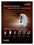
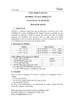
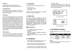
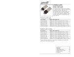
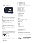
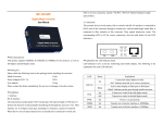
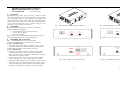
1.
RS-485/422/232 to Fibre Converter
DB9/Terminal Block to ST Fibre
(620−0441−000)
User's Manual
Overview
RS-485/422/232 to fibre optic converter is used to extend
distance up to 2Km over the multi-mode fibre or up to 20Km
over the single-mode one. The converter is equipped with
multiple interface circuit such as RS-232, RS-422 and RS485 2/4-wire. This converter can be used as a standalone unit
or as a slide-in module to the 19" converter rack (up to 10
units) for use at a central wiring closet.
2.
Fig. 1 RS-485/422/232 DB9 to Fibre Converter
Checklist
Before you start installing the Converter, verify that the
package contains the following:
⎯ The RS-485/422/232 to Fibre Converter
⎯ AC-DC Power Adapter
⎯ This User's Manual
Please notify your sales representative immediately if any of
the aforementioned items is missing or damaged.
3.
RS485
WIRING
2wire 4wire
DB9
CONFIG
485/422
232
Fig. 3 RS-485/422/232 Terminal Block to Fibre Converter
RS485
WIRING
2wire 4wire
Installing the Converter
STANDARD
CONFIG
1
RS232
485/422
2
3
Fig. 2 DB9 to Fibre Converter Side Panel
2
1
4
RS232
485/422
2
3
4
P-UP
P-DOWN
TX-TERM
RX-TERM
1
RESISTOR
RESISTOR
STANDARD
CONFIG
P-UP
P-DOWN
TX-TERM
RX-TERM
Note: The Media Converter is hot-swappable.
⇒ Wear a grounding device for electrostatic discharge.
For as a standalone unit:
⇒ Verify that the AC-DC adapter conforms to your country
AC power requirement, and then insert the power plug.
⇒ Install the media cable for network connection.
For as a slide-in unit:
⇒ Verify that the media converter is the right model and
conforms to the chassis slot. The Media Converter and
Rack are built to match each other in dimensions, DC jack,
DC receptacle and power safety.
⇒ Locate +5VDC power jack on converter back, carefully
slide in and plug to 19" rack +5VDC power receptacle.
⇒ Install the media cable for network connection. The Tx, Rx
fibre and copper cable must be paired at both ends. Please
ensure that the copper cable and its voltage polarity match
the device requirement for 4-wire or 2-wire connection.
Fig. 4 Terminal Block to Fibre Converter Side Panel
3
4.
Switches Setting, Terminal Block, DB9
STANDARD
CONFIG SW
DB9 CONFIG
RS-485
SW
WIRING SW
RS-232
RS-232
RS-232
Don't care
RS-485 4 wire
RS-485/422
RS-485/422
4 wire
RS-485 2 wire
RS-485/422
RS-485/422
2 wire
RS-422
RS-485/422
RS-485/422
4 wire
Note:
Terminal block model (RS-C200ST-2, RS-C200ST-4) is not
equipped with the "DB9 CONFIG" switch, the available
connections by the two SW setting are:
Protocol &
Connection
STANDARD
CONFIG SW
DB9 CONFIG
RS-485
SW
WIRING SW
RS-232
RS-232
NA
Don't care
RS-485 4 wire
RS-485/422
NA
4 wire
RS-485 2 wire
RS-485/422
NA
2 wire
RS-422
RS-485/422
NA
4 wire
4
• Terminal Block for Copper Wires
RS485/422/232 protocol/connection via Terminal Block
T-(-)
T+(+)
R+
RGND
GND
TXD
RXD
1
2
3
4
5
6
7
8
RS232
Protocol &
Connection
• RESISTOR SW
(Terminal Resistor/Pull-up and Pull-Down Res. Setting)
RS485/422
• STANDARD CONFIG (copper protocol) SW
Copper port/cable protocol: RS232 or RS485/422 selection.
RS232 : RS-232 protocol/connection, default.
485/422: RS485/422 protocol/connection.
• RS485 WIRING (RS485 2/4-wire) SW
RS485 wires: 2 or 4-wire selection.
2-wire: 2-wire (Copper) at half-duplex mode.
4-wire: 4-wire (Copper) at full-duplex mode, default.
"RS485/4-wire" is also used for RS422/4-wire connection.
• DB9 CONFIG (DB9 connector model only) SW
232
: RS232/DB9 connection, default.
485/422: RS485/422 via DB9 port and setup with
"STANDARD CONFIG" SW accordingly.
For DB9 model and port connection, the available
connections by the three SW setting are:
T-(-)
T+(+)
R+
RGND
GND
TXD
RXD
RS-485/422 TX- or RS-485(2-wire) TX/RXRS-485/422 TX+ or RS-485(2-wire) TX/RX+
RS-485/422 RX+
RS-485/422 RXGND
GND
RS-232 TXD
RS-232 RXD
Key
Bin
Each bin of Terminal Block is equipped with a key. Push and
hold the key to release Terminal Block when plugging in or
removing the copper wire.
RESISTOR SW is used for RS485/422 protocol/connection,
and it will take effect when STANDARD CONFIG is at
"485/422".
The RESISTOR SW 1, 2, 3, 4: All of them are
at "OFF" as default
RX-TERM ON : Enables 130 Ω terminator on RX
TX-TERM ON : Enables 130 Ω terminator on TX
P-DOWN ON : Enables 1k Ω pull down on
RS422/RS485(4-wire) TX- or
RS485(2-wire)TX/RXP-UP ON
: Enables 1k ohm pull up on
RS422/485(4-wire) TX+ or
RS485(2-wire)TX/RX+
RS485/422 4-Wire Connection
RS485 2-Wire Connection
TX/RXTX/RX+
R-(-)
R+(+)
T+
T-
T-(-)
T+(+)
R+
R-
TX/RXTX/RX+
• DB9 Connector for Copper Wires
RS232 protocol/connection via DB9
5 Signal Ground
Unused 9
4 Unused
Unused 8
3 RS-232 TXD
Unused 7
2 RS-232 RXD
Unused 6
1 Unused
Warning:
⎯ The termination and P-UP, P-DOWN resistors are set up in
accordance with the RS485/422 network configuration.
⎯ Ensure that the copper cable and its voltage polarity match
the device requirement for 4-wire or 2-wire connection.
⎯ Improper termination and network configuration will
render the devices to work poorly.
5
RS-232 Cable Connection via DB9
RXD
TXD
GND
2
3
5
3 TXD
2 RXD
5 GND
6
RS485/422 protocol/connection via DB9
If you use DB9 for RS485/422 cable connection, the Pin
definition and assignment are as follows:
5.
LED Description
RS485/422/232 Port
F
DB9 or
Terminal Block
C
5 Signal Ground
Unused 9
7.
ACT
Optic Fibre Port
TX
RX
Model
4 RS-485/422 RX-
Unused 8
RS-485/422/232
Fibre Media Converter
3 RS-485/422 RX+
Unused 7
2 RS-485/422 TX+ or RS-485(2-wire) TX/RX+
Unused 6
LED
You may configure RESISTOR SW for proper termination or
P-UP, P-DOWN resistors in the network connection.
Color
F (FX ACT)
Green
C (Copper ACT) Green
PWR
RS-232
RS-422
RS-485
DB9 or
Terminal
Block
Copper Wire
TX
RS-485/422/232
DB9, Terminal
Fibre Converter
RX
RS-C200ST-1
RS-C200ST-2
PWR
Fig. 6 RS-485/422/232 to ST Fibre Converter Front Panel
1 RS-485/422 TX- or RS-485(2-wire) TX/RX-
Fibre Optic Wire
6.
Green
Function
Blinks when fibre data is received
Blinks when Copper data is
received
Lit when +5V power is coming up
DC Jack and AC-DC Power Adapter
The DC jack's central post is 2.5mm wide and conforms to the
DC receptacle(2.5mm).
DC Jack : 2.5mm
DC Input : +5V
(RS-C200
DC current: full load consumption 0.5A)
Fig. 7 DC+5V Input Jack and Dimension
TX
RX
AC-DC adapter using different AC input voltages is available
for different areas.
Fig. 5 RS-485/422/232 Fibre Optic Network Connection
AC Input:
DC Output:
7
Fibre Technical Specifications
• Standards : TIA/EIA-232(ITU-T V.28)
TIA/EIA-422(ITU-T V.11)
TIA/EIA-485(ISO/IEC8284)
• Model Description :
North America
Europe
U.K.
South Africa
Australia
Japan
5VDC @ 1.0A
8
120VAC 60Hz
230VAC 50Hz
230VAC 50Hz
240VAC 50Hz
240VAC 50Hz
100VAC 50/60Hz
∗RS-C200ST-3
∗RS-C200ST-4
Interface Fibre Type
λ(nm) Distance
DB9(male) ST multi-mode 820
2Km
Terminal
ST multi-mode 820
2Km
ST single20Km
DB9(male)
1310
mode
ST single20Km
Terminal
1310
mode
* Single-mode model is by request
• Data Transfer Rate and Maximum Cable Distance
Connection
RS-232
RS-422/485
RS-422/485
MM Fibre
SM Fibre
Max. Rate Bps
115.2K
90K
500K
*
*
Max. Distance
15m (50ft)
1220m (4000ft)
92m (300ft)
2Km
20Km
* Fibre Optic Rate depends on Copper Port speed
• Copper Wires : 24 to 22 AWG gauge
Attenuation 20dB/1000ft @ 10MHz
Differential Impedance 100Ω @ 10MHz
• Fibre Cable :
50/125, 62.5/125, or 100/140μm multi-mode
8.3/125,8.7/125,9/125 or 10/125μm single mode
• Data Transfer Rate : up to 115.2Kbps (RS-232)
up to 500Kbps (RS-485/422)
• Power Requirement : 1A@+5VDC
• Ambient Temperature: 0° to 50°C
• Humidity
: 5% to 90%
• Dimensions : 26.2(H) × 70.3(W) × 94(D) mm
• Complies with FCC Part 15 Class B and CE Mark
Note:
For connecting this device to Router, Bridge or Switch,
please refer to the corresponding device's Technical Manual.
9