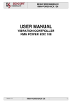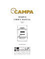
1
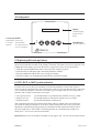
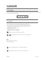
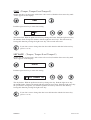
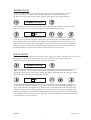
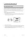
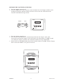
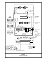
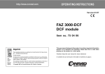
TEMPUS
USER’S MANUAL
Version 1.01
06/2001
12 : 47 : 36
1
2
08/10
3
4
TEMPUS
Australian Agent:
HERTZ ELECTRONICS
A. B. N. 6 9 0 8 6 6 5 1 0 1 4
P. O. B o x 1 1 5 A N N A N D A L E N S W 2 0 3 8
18 Rose Street, ANNANDALE NSW 2038
PH: -61-2-8205 0575
FAX: -61-2-9571 9754
Email: [email protected]
www.hertzelectronics.com.au
A. GENERAL
1. Introduction
The TEMPUS master clock has been designed for controlling electro-mechanical slave clocks
with the following properties:
1. Slave Clock, indoor/outdoor, short-circuit protected 24VDC alternating impulse output
with a current handling capacity of 500mA.
2. Tower Clock with 240VAC 3-wire control output using relays for added reliability.
AVAILABLE TEMPUS VERSIONS
Tempus
Time only - 1x 24V slave clock and 1x 3-wire tower clock output
TempusGPS
Time only - with built-in GPS receiver
Tempus E
Time and 2x bell hammer control outputs, FET based, for direct connection of
2x independent electro-mechanical bell hammers. This enables hour, ½ hour and
quarter hour strokes, the angelus and/or simulated single or peal of bells.
Tempus P
Time and 2x relay programs for school bells, lighting, etc.
TEMPUS MENU:
The Tempus controller provides three menu levels:
The main display provides information about the time and date.
The user menu allows to set the system variables, like time and date,
slave clocks/tower clock synchronisation, turning bell hammers on/off, etc.
Function Menu: The function menu allows the installer to set the system parameters, e.g.
impulse type, impulse duration, programming relays and bell hammers.
This menu can be protected against unauthorised changes by a security
PIN code.
Main display:
User menu:
BACKLIGHTING:
All Tempus versions provide display backlighting for comfortable programming in poor lighting
conditions.
TEMPUS
1
Version 1.01
2. Options
Following options are available for the Tempus controller:
OPTIONAL EXTERNAL SYNCHRONIZATION:
Three time code receivers are available for synchronisation:
DCF Time Code (Europe only) This receiver is available for most of mainland Europe. The
Tempus accuracy will not deviate for more than 1 sec from Middle-European
time.
MSF Time Code
(UK only) This receiver is available for the UK area. The Tempus accuracy
will not deviate for more than 1 sec from Western-European time.
GPS Receiver
(world wide) The GPS receiver can be used anywhere in the world. It receives
the atomic time from 24 satellites revolving around the earth. The Tempus
accuracy will increase to within 100uS from GMT/UTC
COMPUTER LINE:
This option enables the transfer of time and date via the RS232 serial code to a computer (via remote
control + transferring data load-pattern)
OPTIONAL PIM:
The PIM (Plug In Memory Module) enables the back-up of the Tempus program and allows software
transferral from one controller to another.
3. TEMPUS Specifications
Supply voltage:
230VAC 50/60 Hz +5% / -10% (standard)
120VAC 50/60Hz +5% / -10% (on request)
Outputs:
1x 3-wire control output using 2x relays for reliable operation
for tower clock movements
1x 24VDC alternating impulse output, output capacity: 500mA
2x spark-free FET outputs for the direct control of bell hammers
max. output capacity: 5A (Tempus E only)
Power Consumption:
Case Material:
Dimensions:
Weight:
14W at 230VAC (without bell hammers)
Polystyrene UL94-V0
260 x 160 x 85mm (height x width x depth)
1.100 kg
TEMPUS
2
Version 1.01
4. Front panel
12 : 47 : 36
08/10
Display
with back lighting
and time & date
display
Green Synch LED
LED flashing: Search mode
Led steady: Synchronisation
No synchronisation or
LED off:
no receiver installed
1
2
3
4
Push Buttons
Up, down, right, left
TEMPUS
5. Replacing the back-up battery
The back-up battery has a life expectancy of approx. 10 years. This battery is bundled with the
quartz crystal timebase module of the Tempus controller. The battery need to be replaced every
7 years before the battery goes flat. How best to replace the battery is described below:
1. With the optional PIM module take a back-up of the Tempus program.
2. Turn the unit off and then replace the battery/timebase module.
3. Insert the PIM unit with the red arrow facing the Tempus.
4. Turn the Tempus on. The PIM will automatically reload the program.
6. GPS, DCF or MSF synchronization
If a time code receiver has been installed, use following method to check if the Tempus
master clock has synchronised to the external time codes: If it has synchronised the green light
is on. Switch the Tempus on and off to check the signal strength. This also forces the unit to
initialize and read the external time code signal.
1. No signal received
2. Signal received
3. Synchronisation
- green LED flashes in synchronisation with the receiver’s LED
- green LED flashes in alternation with the receiver’s LED
- green LED illuminates continuously
The synchronisation takes place during night time at the top minute (00 second) between
03:00 and 05:00am provided there is no power failure during this time. If the green LED
illuminates continuously during daytime it would indicate that synchronisation has taken
place the night before. If the LED is off during daytime no synchronisation would have
taken place. (or no receiver has been installed).
Please note: the receiver should be installed at least approx. 80 - 150 cm away from the master.
TEMPUS
3
Version 1.01
B. SOFTWARE
1. Main display
Turn the TEMPUS master controller on. Shortly after turn-on the main display will automatically show
the current time and numerical date.
12 : 47 : 36
08/10
2. User menu
The user menu allows to set the system variables, like time and date,
slave clocks/tower clock synchronisation, turning bell hammers on/off, etc.
1. Change time and date (Necessary only without a time code receiver)
2. Synchronise impulse slave clocks
3. Synchronise tower clocks
4. Turning hammers on/off (Tempus E)
5. Turning relays on/off (Tempus P)
2
With the down arrow key enter the user menu.
2
1
With the up or down arrow keys select following functions:
Time
Date
Tower Clock (3-wire 230VAC)
Slave Clock (24VDC)
3
With the right arrow key access the selected function.
4
With the left arrow key go back one step without change.
TEMPUS
4
Version 1.01
TIME (Tempus, Tempus E and Tempus P)
Change the time (not necessary with a time code receiver) Push the down arrow key until
‘Time’ appears on the display.
2
3
TIME
Push the right arrow key to enter time setting
3
1
12 47
2
3
The hours flash. With the up/down arrow keys change the hours. Push the right arrow key
the minutes flash. Change the minutes with the up/down arrow keys. The time starts by
leaving this function pressing the right arrow key. The seconds start at 00.
4
If you don’t want to change the time leave this function with the left arrow key.
(press 1x or 2x)
SET DATE
(Tempus, Tempus E and Tempus P)
Change the date (not necessary with a time code receiver) Push the down arrow key until
‘Date’ appears on the display.
2
3
DATE
Push the right arrow key to enter date setting
3
1
15 OCTOBER 08
2
3
The day flashes. With the up/down arrow keys change the day. Push the right arrow key
the month flashes. Change the month with the up/down arrow keys. Push the right arrow key
the year flashes. Change the year with the up/down arrow keys. The new date starts by
leaving this function pressing the right arrow key.
4
TEMPUS
If you don’t want to change the date leave this function with the left arrow key.
(press 1x or 2x)
5
Version 1.01
TOWER CLOCK
Set or correct the tower clock. For the master to be able to automatically set or correct
the tower clock it is essential to enter the time displayed on the clock dial. Press
the down arrow key until ‘Tower Clock’ appears in the display. The output turns off.
2
3
TOWER CLOCK
Enter this function with the right arrow key. The output turns off and the tower clock stops.
Take a look at the tower clock face and enter the time displayed on the dial.
3
1
12 47
2
3
The hours flash. With the up/down arrow keys set the hours to the same hour as displayed
on the dial. Then push the right arrow key again. The minutes flash. With the up/down arrow
keys set the minutes to the same time as displayed by the minute hand on the dial. Press the
right arrow key to confirm. The setting process starts automatically. The master compares the
dial time, which was just entered, with the internal quartz timebase and corrects the clock. If
the time difference is 40min or less ahead of time the tower clock will wait.
SLAVE CLOCK
Set or correct the 24V impulse slave clocks. For the master to be able to automatically set or correct
the impulse clocks it is essential to enter the time as displayed on the clock dials. Press
the down arrow key until ‘Slave Clock’ appears in the display.
2
3
SLAVE CLOCK
Enter this function with the right arrow key. The output turns off and the impulse clocks stop.
Take a look at the slave clock faces and enter the time displayed on the dials. If there is a
discrepancy between slave clock dials, correct the displays manually until all clocks are on the
same time. Then enter the time displayed on all dials.
3
1
12 47
2
3
The hours flash. With the up/down arrow keys set the hours to the same hour as displayed
on the dials. Then push the right arrow key again. The minutes flash. With the up/down arrow
keys set the minutes to the same time as displayed by the minute hands on the dials. Press the
right arrow key to confirm. The setting process starts automatically. The master compares the
just entered dial time with the internal quartz timebase and corrects the slave clocks by sending
rapid impulses until the dials are on the right time. If the time difference is 40min or less ahead
of time the slave clock(s) will wait.
TEMPUS
6
Version 1.01
C. OPTIONAL PIM-MODULE
PIM - Plug-in Memory Module
The PIM (Programmable plug-in memory module) acts like a memory stick that can back-up
and restore the Tempus software + programs. The PIM module consists of a printed circuit
board inside a small housing with two 9-pin D-connectors on either end. The PIM housing is
marked with a red and green arrow to indicate the back-up or restore directions.
If the red arrow faces the Tempus the contents of the PIM will be restored to the master clock.
If the green arrow faces the controller the PIM will make a back-up of the Tempus software
and program.
BACK UP THE CONTENTS OF THE TEMPUS
1. Turn the Tempus controller off.
2. Insert the PIM into the 9-pin connector on the left hand side of the Tempus with the arrows
pointing away from the controller and the green arrow closest to the unit. This indicates the
contents of the Tempus are being copied.
RED
GREEN
12 : 47 : 36
1
2
08/10
3
4
TEMPUS
3. Turn the Tempus controller on.
4. The contents of the controller are now automatically written to the PIM module. After a full
back-up has been made the Tempus screen will return to the main display. If a PIM is found
to be faulty the Tempus controller will confirm this with the message ‘BAD PIM!’.
5. Before removal of the PIM module turn off the controller. Remove the PIM. Turn the Tempus
back on. Store the PIM in a save place for later use.
TEMPUS
7
Version 1.01
RESTORE THE CONTENTS OF THE PIM
1. Turn the Tempus controller off.
2. Insert the PIM into the 9-pin connector on the left hand side of the Tempus with the arrows
pointing towards the controller and the red arrow closest to the unit. This indicates the
contents of the PIM are being restored.
GREEN
RED
12 : 47 : 36
1
2
08/10
3
4
TEMPUS
3. Turn the Tempus controller on.
4. The contents of the PIM are now automatically loaded into the Tempus. After a full
restore has been made the Tempus screen will return to the main display. If a PIM is found
to be faulty the Tempus controller will confirm this with the message ‘BAD PIM!’.
5. Before removal of the PIM module turn off the controller. Remove the PIM. Turn the Tempus
back on. Store the PIM in a save place for later use.
12 : 47 : 36
1
2
08/10
3
4
TEMPUS
TEMPUS
8
Version 1.01
24V DC
Impulse
output
ADE
AUSTRAL
AUST R AL IAN
M ADE
IAN M
AUST R AL IAN M ADE
Radio
PIM
Back-up
Module
GPS
Receiver
Input
LCD Display
with back
lighting
12 : 47 : 36
Program restore
or new program
to Tempora
1
2
3
Programming
Buttons
4
TEMPUS
Program back-up
to PIM
HAMMERS
TOWER CLOCKS
POWER
KL5
KL3
On/Off Button
KL3
A B CAB L' N
Turn off Tempora.
Install PIM. Turn on
Tempora. Automatic
back-up or restore.
Please follow the
screen.
M2 M+ M1 M+
NL
Jumper
240V 50Hz
Mains Supply
a
b
24VDC TEMPUS 4 Outputs
Impulse
Output
A
B
ON
OFF
C
L'
N
N L
Tower Clock Movement
Minute Impulse
MS
230 VAC
GPS
Input
R2
R3
Tower Clock
F2 = 0.8AT slow
GPS
A
Over Voltage
Protection
B
240VAC 50Hz
C
Cable Size >= 3x 0.75 mm
2
TEMPUS
Connection Diagram
Earth
N
L
Optional
GPS
Receiver