Download Oilless scroll pump Service Manual
Transcript
Authorized Distributor Only
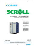
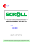
OILFREE SCROLL AIREND
MAINTENANCE MANUAL AND PARTS LIST
MODEL
BC-KL32L(H)
BC-KL52L(H)
COAIRE CORPORATION
All rights reserved
January, 2013
For proper and safe use of the compressor, please follow all instructions and safety precautions as identified in
this manual, along with general safety regulations and practices.
Printed in U.S.A.
SAFETY AND PRECAUTION
PRECAUTIONS
CAUTIONS
Before you install the air compressor you should take the time to carefully read all the
instructions contained in this manual. Electricity and compressed air have the potential to
cause severe personal injury or property damage. Before installing, wiring, starting, operating
or making any adjustments, identify the components of the air compressor using this manual
as a guide. The operator should use common sense and good working practices while
operating and maintaining this unit. Follow all procedures and piping accurately. Understand
the starting and stopping sequences. Check the safety devices in accordance with the following
procedures contained in this manual. Maintenance should be done by qualified personnel,
accurately with proper tools. Follow the maintenance schedule as outlined in the manual to
ensure problem free operation after start up.
SAFETY PRECAUTIONS
BEFORE INSTALLING THE COMPRESSOR OR PERFORMING ANY MAINTENANCE READ THIS
MANUAL CAREFULLY.
WARNINGS
COMPRESSED AIR AND ELECTRICITY
ELECTRICITY ARE DANGEROUS. BEFORE DOING ANY WORK ON THIS UNIT, BE SURE
THE ELECTRICAL SUPPLY HAS BEEN SHUT OFF(LOCKED AND TAGGED) AND THE ENTIRE COMPRESSOR
SYSTEM HAS BEEN VENTED OF ALL PRESSURE.
1. Do not remove the cover, loosen or remove any fittings, connections or devices when this unit is operating or in
operation. Hot liquid and air that are contained within this unit under pressure can cause severe injury or death.
2. The compressor has high and dangerous voltage in the motor, the starter and control box. All installations must be in
accordance with recognized electrical procedure. Before working on the electrical system, ensure that the system's
power has been shut off by use of a manual disconnect switch. A circuit breaker or fuse switch must be provided in
the electrical supply line to be connected to the compressor. The preparation work for installation of this unit must
be done on suitable ground, maintenance clearance and lightning arrestors for all electrical components.
3. Do not operate the compressor at a higher discharge pressure than those specified on the compressor nameplate. If
so an overload will occur. This condition will result in electric motor shutdown.
4. Use only safety solvent for cleaning the compressor and auxiliary equipment.
5. Install a manual shut off valve(isolation type) in the discharge line for service work.
6. Whenever pressure is released through the safety valve during operation, it is due to excessive pressure in the
system. The cause of excessive pressure should be checked and immediately corrected.
7. Before doing any mechanical work on the compressor,
a) Shut down the unit.
b) Electrically isolate the compressor by use of the manual disconnect switch in the power line to the unit. Lock and
tag the switch so that it cannot be operated.
8. Before starting the compressor, the maintenance instructions should be thoroughly read and understood.
9. After maintenance work is completed, covers must be securely closed.
10. For questions contact your distributor before proceeding.
1
STATEMENT OF WARRANTY TERMS & CONDITIONS
General Provisions:
a) Coaire warrants our air compressors and scroll systems (henceforth called “products”) to be free from material defects and
workmanship under proper use, operating conditions, installation, and application based on the terms and conditions set forth
below. Coaire offers no other warranty, whether expressed or implied, including any warranty of merchantability or fitness for a
particular purpose.
b) Any air compressor, part or material found to be defective will be repaired, replaced or refunded at the sellers option free of charge,
provided that Coaire is notified with the stated warranty period.
c)
All claims shall be made in writing using our warranty claim report located within each service manual.
d) All claims must have the start-up report sheet included. The start-up report sheet is located within each service manual.
e) All returns of allegedly defective equipment must have prior written authorization. Said authorization shall be obtained through our
service department. Any compressors, parts, or materials must be returned freight prepaid to the manufacturers factory within (30)
days of the return authorization date. Any shipment returned to the factory collect will be refused.
f)
If an item is found to be warrantable, the repaired or replacement item will be returned normal ground freight, prepaid. Expedited
return freight costs are the responsibility of the requestor.
g) Any replacement part or material is warranted to the extent of the remaining warranty period
Standard Period of Warranty:
h) Coaire warrants our system(s) for a period of (15) months from shipment, (12) months from the documented start-up, or 5,000 hours
of use, whichever occurs first. During such period, Coaire will be liable for all product or material defects and will assume the costs of
repair or replacement so long as the product(s) are located within the continental United States or Canada. In addition, the
product(s) must be easily accessible by service personnel for removal.
i)
In addition to item “g” above, Coaire warrants the air compressor air end (compressor only), parts only (no labor) for a period of (27)
months from shipment, (24) months from the documented start-up, or 7,500 hours of use, whichever occurs first.
j)
Coaire product(s) located outside of the continental United States or Canada shall include a parts only warranty for a period of (15)
months from shipment, (12) months from the documented start-up, or 5,000 hours of use, whichever occurs first.
Exclusions – Coaire shall have no warranty obligation for:
k) Products not installed in accordance with our written instructions and specifications
Operated in an unsuitable environment, in excess of stated product parameters, modified in any way, or used in an improper manner
l)
m) That have not been properly maintained per Coaire’s written instructions
n) Use of corrosive materials or insoluble lubricants
o) Normal wear and tear items are not included under this warranty
p) Any OEM (original equipment manufacturer) component that may be used within our products will carry the original manufacturer’s
warranty
q) Product is properly stored prior to installation
r)
Product not installed by a competent, qualified installer
s)
Product which may have been damaged during shipment
Liability Limitation:
t)
Coaire shall not be liable for any damages (incidental, consequential, punitive, et al.) that may arise from the use of our product.
Coaire’s liability in all events, is limited to and shall not exceed, the original purchase price.
Suitability of the Product:
u) Jurisdictions has various codes, Coaire makes no claim as to the suitability for all jurisdictions. It is the buyer’s responsibility to ensure
the product, installation, and use comply with local jurisdictions.
Identification plate:
v) Coaire products have identification plates on the air compressors as well as on the enclosures. These data plates show the primary
information for the product. This data should always be referred to when calling the manufacturer or distributor. The removal or
alteration of the identification plate(s) shall immediately void all warranty.
Who to contact for warranty claims:
Web: www.coaire.com
Phone: (562) 496-3935
Fax: (562) 463-4928
All freight damage claims should be filed within 15 working days and should be directed to the carrier.
2
CONTENTS
SAFETY AND PRECAUTIONS
STATEMENT OF WARRANTY TERMS AND CONDITIONS
1. AIREND MAINTENANCE TABLE
5
2. REGULAR MAINTENANCE
6
2.1 Preparation
6
2.1.1 Tools
6
2.2 Disassembly Order and Method
6
2.2.1 Fan Duct
6
2.2.2 Fan Cover (External)
6
2.2.3 Airend Pulley
7
2.2.4 Fan Cover (Internal)
7
2.2.5 Fixed Scroll Set
7
2.3 Cleaning
7
2.3.1 Orbiting Scroll Cooling Fin
7
2.3.2 Fixed Scroll Cooling Fin
8
2.3.3 Fan Cover & Duct
8
2.3.4 Sirocco Fan
8
2.4 Maintenance
9
2.4.1 Injecting Grease Into Orbiting Scroll Center Bearing
9
2.4.2 Injecting Grease Into Pin Crank Bearing
10
2.4.3 Tip Seal Set Exchange
11
2.5 Assembling
15
2.5.1 Fixed Scroll Set
15
2.5.2 Sirocco Fan & Fan Cover, Duct
15
3. DISASSEMBLING MAINTENANCE (OVERHAUL)
17
3.1 Maintenance Jig and Tool
17
3.2 Exchange Parts
18
3.3 Disassembling Order and Method
20
3.3.1 Fan Duct
20
3.3.2 Fan Cover (External)
20
3.3.3 Airend Pulley
20
3.3.4 Fan Cover (Internal)
20
3.3.5 Fixed Scroll Set
21
3.3.6 Orbiting Scroll Set
21
3.3.7 Crank Shaft Set
22
3
3.3.8 Ball Bearing
23
3.4 Cleaning
23
3.4.1 Orbiting Scroll Cooling Fin
23
23
3.4.2 Fixed Scroll Cooling Fin
3.4.3 Fan Cover & Duct
24
3.4.4 Sirocco Fan
24
3.4.5 Housing
24
3.5 Assembling
25
3.5.1 Ball Bearing Housing Assembling
25
3.5.2 Bearing Cover Assembling
26
3.5.3 Crank Shaft Housing Assembling
27
3.5.4 Orbiting Scroll Center Bearing Assembling
27
3.5.5 Pin Crank Set Assembling
27
3.5.6 Assembling Orbiting Scroll Set in Housing Set
28
3.5.7 Adjusting Axial Direction Gap
30
3.5.8 Assembling Tip Seal Set
33
3.5.9 Fixed Scroll Set Assembling
35
3.5.10 Sirocco Fan & Fan Cover, Duct
35
4. AIREND SECTIONAL VIEW
37
5. AIREND EXPLODED VIEW
38
6. ASSEMBLING TORQUE TABLE
39
4
1. AIREND MAINTENANCE TABLE
Run Time(Hours)
2,500
Item
Action needed
Bearing Grease
Re-grease
*
Tip Seal Kit
Replace
*
Sirocco Fan
Clean
○
○
Air-end Fin
Clean
Fan Duct, Cover
Clean
○
○
Sirocco Fan
Clean
○
○
Intake Filter
Clean, Replace
500
5,000
10,000
Or
1
year
Or
2 years
Or 6 month
○
Every 2500hrs or less
○
○
Remarks
Every 2500hrs or less
Note
1) ○ : clean, : replace or regrease
2) (*) : every 5,000 hours for high pressure pump(140psi)
CAUTION
① Routine maintenance and disassembly maintenance, must be applied when the hourly or time
schedule comes due, whichever comes first.
② Regular maintenance, disassembly maintenance standard: is applied when the standard use
condition and installation environment are satisfactory and when the surrounding environment or
operation condition is severe, the period or time for regular maintenance and disassembly maintenance
must be shortened.
③ The regular maintenance and disassembly maintenance are not part of the warranty.
④ Cleaning: When the surrounding environment or operation condition are service
(high heat or dirty environment), the cleaning time or periodic maintenance intervals must be
shortened. (BC-KL32,52L/H) per 2,500 hours)
5
2. REGULAR MAINTENANCE
2.1 Preparation
1) Tools
① screw driver (+ cross-tip)
② 17mm hand socket, extension, ratchet handle
③ Holding Spanner
④ Low pressure compressed air
⑤ Torque wrench, in-lbs
2.2 Disassembly order and method
1) Fan duct
① Loosen the 3 upset type M6 bolts and separate the fan duct.
2) Fan cover (external)
① Loosen the 5 tapping screw M6 bolts and separate the fan cover.
6
3) Airend pulley
① Take off the hexagon socket head cap screws with a spanner in the balance
weight of pulley rotation direction and remove the pulley/fan assembly.
4) Fan cover (internal)
① Separate the fan cover by loosening the 3 screws.
.
5) Fixed scroll set
① Separate the fixed scroll by removing six(6 ) self locking nuts.
2.3 Cleaning
1) Orbiting scroll cooling fin
① Remove dust and dirt attached to the cooling fin using compressed air gun.
② Do not clean the orbiting scroll set with organic solvent (thinner, solvent)
7
2) Fixed scroll cooling fin
① Remove dust and dirt attached to the cooling fin using compressed air gun.
② Do not clean the orbiting scroll set with organic solvent (thinner, solvent).
NOTE
Damage may occur to special protective coating.
3) Fan cover & duct
① Remove dust and dirt attached to the fan cover and duct using air gun.
4) Sirocco fan
① Remove dust and dirt attached to the sirocco fan using air gun.
8
2.4 Maintenance
NOTE
Conduct maintenance in a clean location to prevent pollution and damage to the scroll
maintenance parts.
parts. Use only recommended high temperature grease. (Consult your
distributor)
1) Injecting grease into orbiting scroll center bearing
① Remove the dust cap on the top rib or left of housing.
② The crank shaft key must be in 7 o'clock direction when seen from the front.
③ Insert the nozzle connected to the grease gun into the housing dust cap hole
and connect to the grease nipple attached to the crank.
NOTE
Move the crank shaft from left to right and check the connection of the grease
nozzle and nipple. Bearing should rotate smoothly and quietly.
9
④ Press the grease gun button and inject grease.
NOTE
Keep the nipple securely on the grease gun nozzle so that grease does not leak between
the grease gun nozzle and nipple. Rotate the crank so the grease is applied evenly within
the bearing, do not over grease.
⑤ After injecting the grease fit the housing with the dust cap.
2) Injecting grease into pin crank bearing
① Use a flat screw driver to remove the 3 bearing grease caps behind the housing.
② Apply grease onto the pin crank orbiting scroll shaft bearing. Use a needle
grease nozzle, apply grease evenly within the bearings, do not over grease.
10
③ Stick the grease gun nozzle closely into the pin crank bolt nipple and press the
grease gun button about 3 to 4 times to supply grease to the housing bearing.
CAUTION
Watch closely so that grease does not leak between the grease gun and pin crank nipple
when injecting the grease.
④ Re-assemble the 3 bearing grease caps into its original position, do not force
them, hand pressure is adequate.
3) Tip seal set exchange
① Separate the high pressure and low pressure tip seal from the top seal by
using pick in the fixed scroll set.
11
② Using the same method, separate the dust seal and back up tube.
③ Using the same method, separate tip seal from the orbiting scroll set.
④ Lift about 2mm from the high pressure central tip seal and insert into the high
pressure tip seal vertical hem and fix with finger tips.
2mm
CAUTION
Shaped slit on the side and the bottom of the tip seal,
seal, wrap facing the center of the
insertion.
insertion.
12
Direction of Slit Side
CAUTION
Insert tip seal so that lip side (slit
(slit side)
ide) of tip seal contacts the bottom of seal groove and
faces inside of scroll wrap.
wrap.
If you
you miss, the performance of the compressor
compressor may be impaired and wrap is injured by
high temperature
temperature.
.
erature
Remove HP tip seal and LP tip seal
from FS set and OS set by using tip
of sharp tool.
HP tip seal : Length is short.
LP tip seal : Length is long.
Insert high pressure tip seal using the same method.
Insert low pressure tip seal into the end of the high pressure tip seal and press
down with finger tip and insert and cut according to tip seal groove with a knife.
13
Insert low pressure tip seal using the same method.
When fixing a backup tube to the fixed scroll set, the joint must face 6 o'clock
direction.
Fit the dust seal on top of the back-up tube.
Dust seal
CAUTION
The top and bottom are not distinguishable when assembling dust seal.
14
2.5 Assembling
1) Fixed scroll set
① Assemble the fixed scroll set according to the housing parallel pin location.
② Temporarily assemble 6 self-locking nuts then tighten with cross pattern
sequence using a torque wrench.
[ TORQUE ]
BCBC-KL3
KL32L(H) : 260 lbf.inch(300
lbf.inch(300㎏
300㎏f.㎝
f.㎝)
BCBC-KL5
KL52L(H) : 260 lbf.inch(300
lbf.inch(300㎏
300㎏f.㎝
f.㎝)
2) Sirocco fan & fan cover, duct
① Fit 3 screws onto the fan cover (internal).
② Tighten the hexagon socket head cap screws with a spanner in the balance
weight of pulley reverse-rotation direction to assemble the pulley sirocco fan assembly.
☞ Torque : 174 lbf.inch(200
lbf.inch(200㎏
200㎏f.㎝
f.㎝)
15
③ Close the fan cover (external) with self-tapping screw.
CAUTION
When tightening tapping screw, please be careful so that the screw thread does
not get damaged.
16
3. DISASSEMBLING MAINTENANCE (OVERHAUL)
3.1 Maintenance jig and tool
① orbiting scroll center bearing disassembling jig
② orbiting scroll set axial direction gap adjusting jig
③ Crank shaft set injection press 1TON
④ Torque wrench (1) : 0~87 lbf.inch(0~100㎏f.㎝), Torque wrench (2) : 0~347
lbf.inch(0~400㎏f.㎝)
⑤ socket wrench : M5, M6, M8, M10
⑥ hand socket : 17mm & extension
17
⑧ Phillips screw driver
3.2 Exchange parts
① orbiting scroll pin crank bearing cover set
② Housing pin crank bearing cover set
③ Pin crank set
④ Crank shaft set
18
⑤ orbiting scroll center bearing
⑥ orbiting scroll center bearing grease seal
⑦ Fixed scroll tip seal set(HP tip seal : Length is short, LP tip seal: Length is Long)
⑧ Orbiting scroll tip seal set(HP tip seal:Length is short,LP tip seal:Length is Long)
⑨ Dust seal, backup tube
19
3.3 Disassembling order and method
1) Fan duct
① Loosen the 3 type M6 bolts and separate the fan duct.
2) Fan cover (external)
① Loosen the 5 self-tapping screws(M6) and separate the fan cover.
3) Airend pulley
① Take off the hexagon socket head cap screws with a spanner in the balance
weight of pulley rotation direction and separate the airend pulley, as well as the sirocco
fan assembly.
4) Fan cover (internal)
① Separate the fan cover by loosening the 3 upset bolts.
20
5) Fixed scroll set
① Loosen the 6 self-locking nuts and separate the fixed scroll set.
6) Orbiting scroll set
① Remove the 3 bearing covers behind the housing assembly using a M6 socket
wrench, and remove the 3 pin crank bolts using a 13mm hand socket by placing the
spanner in the pulley balance weight rotating counter-clockwise.
② Hold the orbiting scroll set with the hand and remove from the housing
assembly.
CAUTION
Do not remove the orbiting scroll rear plate fit M5 hexagon socket head cap screws and
orbiting scroll of the orbiting
orbiting scroll set.
21
③ Remove the crank bearing assembly cover hexagon socket head cap screws of
the orbiting scroll rear plate and remove the pin crank set by pulling.
④ Remove the O-ring using a o-ring pick.
7) Crank shaft set
① Remove the hexagon socket head cap screws of the bearing cover attached to
the housing.
② Support the housing set with a jig and remove the crank shaft with a press.
- Directly press the crank shaft set with a press.
- Apply the press load gradually, and when the crank shaft assembly starts to
move, work at minimum load.
☞ Press load : 694 lbf.inch
lbf.inch (800kgf.cm
800kgf.cm)
.cm)
22
8) Ball bearing
① Using a jig, remove the ball bearing of housing with a press.
WARNING
Be careful not to damage the housing when using a jig.
3.4 Cleaning
1) Orbiting scroll cooling fin
① Remove dust and dirt attached to the cooling fin using compressed air.
② Do not clean the orbiting scroll set with organic solvent (thinner, solvent).
CAUTION
Damage may occur to protective coating on metal components.
2)
Fixed scroll cooling fin
① Remove dust and dirt attached to the cooling fin using air gun.
② Do not clean the orbiting scroll set with organic solvent (thinner, solvent).
23
3) Fan cover & duct
① Remove dust and dirt attached to the fan cover and duct using air gun.
4) Sirocco fan
① Remove dust and dirt attached to the sirocco fan using air gun.
5) Housing
① Remove dust inside the housing using a air gun. For dirt not removable with an
air gun, use a brush or a dry cloth.
CAUTION
Do not use organic solvent.
Damage may occur to protective coating on metal components.
24
3.5 Assembling
1) Ball bearing housing assembling
① Check whether the part is the correct part.
② Before installing the bearing, apply some grease to the bearing contact area of
the housing.
③ Support the inside of the housing using 3 jigs, and install the ball bearing using
a jig, with a press.
CAUTION
Use caution on the installation
installation of ball bearing.
④ Bearing installation load: 1100 lbf(500㎏f)
⑤ Remove the bearing from inside of the bearing to the opposite side.
25
2) Bearing cover assembling
① Screw in the bearing cover with hexagon socket head cap screws using proper
torque.
☞ Tightening torque: 61 lbf.inch(70
lbf.inch(70㎏
70㎏f.cm)
f.cm)
3) Crank shaft housing assembling
① Support the housing set with a jig and install the crank set with a press.
② Before installing the crank shaft, apply some grease to the bearing contact
surface in the housing installation.
☞ Press injection load: 694 lbf.in(800
lbf.in(800㎏
800㎏f.cm)
③ Screw in the bearing cover with hexagon socket head cap screws using proper
torque.
☞ Closing torque: 61 lbf.inch(70
lbf.inch(70㎏
70㎏f.cm)
f.cm)
26
4) Orbiting scroll center bearing assembling
① Put the orbiting scroll center bearing on top of the orbiting scroll set and install
using jig, with a press.
② Before installing the bearing, apply some grease to the orbiting scroll center
bearing contact area.
③ Place the oil seal on top of the orbiting scroll center bearing and install using a
jig, with a press.
CAUTION
The oil seal must be on the same side as the top boss of the orbiting scroll set.
5) Pin crank set assembling
① Apply grease from the cartridge onto the 6 O-rings and insert into the O-ring
groove of orbiting scroll set.
27
② Apply grease to the rest of the O-rings and insert into the crank set.
③ Insert the crank set into the orbiting scroll set and tighten the bearing cover
with hexagon socket head cap screws once, then a second time with a torque wrench.
☞ 1st torque: 17.4 lbf.inch(20
lbf.inch(20㎏
20㎏f.cm)
f.cm)
☞ 2nd torque: 34.7 lbf.inch(40
lbf.inch(40㎏
40㎏f.cm)
f.cm)
④ Turn the pin crank set by hand and check whether it rotates smoothly.
6) Assembling orbiting scroll set in the housing
① Position the location of crank shaft balance weight horizontally.
② Determine the location of pin crank of orbiting scroll set.
28
③ Adjust the location so that the eccentric part of the pin crank is at the 6 o'clock
position.
④ When assembling orbiting scroll set in the housing, press in evenly top, bottom,
right and left.
CAUTION
Do not apply excessive force.
⑤ Place a flat washer on the housing set back orbiting scroll bearing side and
assemble crank bolt, then use the spanner to tighten the pin crank bolt with
26 lbf.inch(30
30㎏
30㎏f.cm)
f.cm) with the crank shaft secured and tighten with a torque wrench.
29
⑥Tighten the bearing cover with 35 lbf.inch(40㎏f.cm) with 3 hexagon socket head
cap screws
NOTE
In order to prevent loosening of the bolt, apply loctite 242, 542.
⑦ Check the gap in the assembled fixed scroll on the orbiting scroll wrap floor and
housing plane surface.
☞ Gap: 0.2mm
7) Adjusting axial direction gap
① Fix the jig onto the housing plane surface.
☞ Fix 4 parts.
30
② Turn the 3 dial gauge number adjusting board by hand so the long hand of
the dial gauge points at '0'.
③ When the small hand of the dial gauge reads the “O” location, tighten the 3
bearing cover hexagon socket head cap screws behind the housing gradually with evenly
distributed force.
④ Adjusting method when the 3 dial gauge scales indicates ⓐ : -16㎜,
ⓑ : -18㎜, ⓒ : -21㎜
ⓐ
ⓑ
ⓒ
# Stage 1: Tighten the hexagon socket head cap screws of ⓒ equally and adjust at
-16mm of ⓐ.
31
# Stage 2: Tighten the hexagon socket head cap screws of ⓑ equally and adjust at
-16mm of ⓐ.
# Stage 3: Tighten the hexagon socket head cap screws of ⓐ, ⓑ and ⓒ equally
and adjust at -0.13mm.
☞ Adjustment standard: -0.13 ~ -0.14㎜
0.14㎜
⑤ After adjusting, rotate the crank shaft once and check the dial gauge scale
amplitude is within 0.02mm.
⑥ Assemble the grease cap on the bearing cover.
32
8) Assembling tip seal set
① Separate the high pressure and low pressure tip seal from the top seal by
using pick and in the fixed scroll set.
② Using the same method, separate the dust seal and back up tube.
③ Using the same method, separate tip seal from the orbiting scroll set.
④ Lift about 2mm from the high pressure central tip seal and insert into the high
pressure tip seal vertical hem and fix with finger tips.
CAUTION
Shaped slit on the side and the bottom of the tip seal,
seal, wrap facing the center of the
insertion.
insertion.
⑤ Insert high pressure tip seal using the same method.
⑥ Insert low pressure tip seal into the end of the high pressure tip seal and press
down with finger tip and insert and cut according to tip seal groove with a knife.
33
⑦ Insert low pressure tip seal using the same method.
⑧ When fixing a backup tube to the fix scroll set, the joint must face 6 o'clock
direction.
⑨ Fit the dust seal on top of the back-up tube.
Dust seal
CAUTION
The top and bottom is not distinguishable when assembling dust seal.
34
9)
Fixed scroll set assembling
① Assemble the fixed scroll set according to the housing parallel pin location.
② Assemble with 6 self-locking nuts then
torque by using torque wrench using cross pattern sequence.
tighten
with
regulated
☞ Tightening torque:
BCBC-KL3
KL32L(H) : 260 lbf.inch(300
lbf.inch(300㎏
300㎏f.㎝
f.㎝)
BCBC-KL5
KL52L(H) : 260 lbf.inch(3
lbf.inch(300㎏
00㎏f.㎝
f.㎝)
10) Sirocco fan & fan cover, duct
① Fit 3 bolts onto the fan cover (internal).
② Close the hexagon socket head cap screws with a spanner in the balance
weight of pulley (reverse-rotation direction) to assemble the Airend pulley with attached
sirocco fan.
☞ torque : 174 lbf.inch(200
lbf.inch(200㎏
200㎏f.㎝
f.㎝)
35
③ Attach the fan cover (external) with self-tapping screw.
CAUTION
When tightening tapping screw, please be careful so that the screw thread does
not get damaged.
36
4. AIREND SECTIONAL VIEW
①
②
③
④
⑤
⑥
⑦
⑧
⑨
⑩
⑪
⑫
⑬
: INTAKE PORT
: FIXED SCROLL
: ORBITING SCROLL
: DISCHARGE PIPE
: ORBITING SCROLL CENTER BEARING
: TIP SEAL
: FIXED SCROLL DRIVING SURFACE
: ORBITING SCROLL DRIVING SURFACE
: FIXED SCROLL WRAP
: ORBITING SCROLL WRAP
: CRANK SHAFT
: PIN CRANK
: FAN COVER
37
5. AIREND EXPLODED VIEW
38
1)
Part List
PARTS
NO.
PART NAME
QTY.
PARTS
NO.
PART NAME
QTY.
PARTS
NO.
PART NAME
QTY.
1
HOUSING
1
18
BEARING COVER(2)
3
35
OIL SEAL
1
2
FS(FIXED SCROLL)
1
19
BEARING COVER(3)
3
36
GREASE NIPPLE
1
3
FS REAR PLATE
1
20
BEARING COVER(4)
1
37
STUD BOLT
6
4
OS(ORBITING SCROLL)
1
21
SIROCCO FAN
1
38
WASHER NUT
6
5
OS REAR PLATE
1
22
FAN COVER(1)
1
39
O RING
6
6
HP TIP SEAL
2
23
FAN COVER(2)
1
41
HEX SOCKER HEAD BOLT
1
7
LP TIP SEAL
2
24
FAN DUCT
1
42
UPSET BOLT
6
8
BACKUP TUBE
1
25
DUCT PACKING(1)
1
43
TAPPING SCREW
5
9
DUST SEAL
1
26
DUCT PACKING(2)
1
44
DOWEL PIN
2
10
CRANK SHAFT
1
27
OIL SEAL RACE
1
45
DUST PROOF CAP
SOCKET
BOLT
SOCKET
BOLT
2
PLATE
HEAD
PLATE
HEAD
11
COMP. PULLEY
1
28
ANGULAR BEARING
3
46
12
PULLEY WASHER
1
29
ANGULAR BEARING
3
47
13
KEY
1
30
OS DRIVING BEARING
1
48
GREASE CAP
3
14
PIN CRANK
3
31
BALL BEARING
1
49
HEX SOCKET HEAD BOLT
17
15
PIN CRANK HOLDER
3
32
BALL BEARING
1
50
BUTTON BOLT
4
16
PIN CRANK HOLDER
3
33
G SEAL
3
51
SPRING WASHER
52
OS
DRIVING
INNER RACE
17
BEARING COVER(1)
3
34
G SEAL
3
18
15
3
BEARING
6. ASSEMBLING TORQUE TABLE
Item
Part
standard
Torque (㎏f.㎝)
① Bearing support area
Hexagon socket head cap screws
M5
40
② Bearing support area
Hexagon socket head cap screws
M6
40
③ Bearing support area
Hexagon socket head cap screws
M6
70
④ Bearing support area
Hexagon socket head cap screws
M6
70
⑤ Pin crank
Hexagon socket head cap screws
M8
200
⑥ Airend pulley
Hexagon socket head cap screws
M8
200
⑦ Fixed scroll set
Nut
M10
300
⑧ Sirocco fan
Bolt
M5
60
CAUTION
When tightening bolts and nuts, use a torque wrench.
39
1
Warranty Claim Report
Please complete the following claim form, your claim will be confirmed by our sales representative.
To : Coaire Technologies, Corporation
8740 Pioneer Blvd., Santa Fe Springs, CA 90670
Tel(562)463-3935.Fax(562)463-4928
Company
Distributor
Address
Date
Model
Serial No.
Run Hours
Setting Press.
Company
Customer
Address
Hrs.
PSIG
OPERATING CONDITIONS
Percent(%) on load
No. of days of operation weekly
Hours per day
Machine setting OL/OL or Mod
1)
%
Days
Hours
Ambient Temperature
Discharge temperature
Compressor area temperature
1)
Environment
·F
·F
·F
1 to 10, 1 being clean, 10 very dirty
Incoming
Voltages
L1 - L2
Volts
L2
- L3
Amp.
L1
- L3
Amp.
Full load amperage at _______ PSIG
Unload amperage at ______
L1
L1
- L2
Amp.
L2
- L3
Amp.
L1
- L3
Amp.
- L2
Amp.
L2
- L3
Amp.
Symptom
Fault Diagnosis
Resolution
Parts required
No. Item Number
01
02
03
04
WRITTEN BY
Labor Cost
Description/MFGR Part Number
Quantity
Labor Time:
Travel Time:
Total Amount:
Hrs x
Hrs x
$
Technicians name:
X
SIGNATURE
40
$/Hrs= $
$/Hrs= $
L1
PSIG
-
L3
Amp.
TECHNOLOGIES CORP.
8740 Pioneer Blvd.,
Blvd., Santa Fe Springs, CA 906770
TEL.(562)463TEL.(562)463-3935 ㆍ FAX(562)463FAX(562)463-4928
STARTUP REPORT
Please fill out completely and return to the factory to validate warranty.
CUSTOMER AND MACHINE INFORMATION
CUSTOMER
ADDRESS
CITY/STATE
PHONE
WRITTTEN BY
FACTORY SHIP DATE
DATE STARTED UP
MODEL NUMBER
SERIAL NUMBER
HOURS ON MACHINE
/
/
/
/
Hrs.
MACHINE INFORMATIONS AND INITIAL STARTUP
Compressor Environment- excellent
, good
, fair
, poor
.
Machine Location – indoors
outdoors
if outdoors, protected from rain? Yes
Approx. ambient temperature______
adequate ventilation? -
Did you check for correct rotation? Yes
Incoming Voltages
L1-L2
No
Yes
No
No
.
Nameplate amperage for voltage used
L2-L3
Volts
.
______
L1-L3
Volts
Full load amperage at _________ PSIG
L1
Amp.
L2
Unload amperage at _________ PSIG
L1
Amp.
L2
Volts
L3
Amp.
Amp.
L3
Amp.
Is the machine on a level and stable surface?
Yes
No
.
Did you have to add lubricant oil? – Yes
No
.
if yes, please indicate amount and exact name and type. (Amount _____ Name ______ Type _____ )
Was a flexible connector used to connect piping? – Yes
No
.
Approx. time spent during startup procedure ___________ Hrs.
Did you advice customer on operation and maintenance of machine?
Yes
No
.
Application and installation comments:
_____________________________________________________________________________________________
___________
_____________________________________________________________________________________________
_____________________________________________________________________________________________
______________________
Machine Sold By(Company) __________________ Sales Person ___________________________
Startup performed by _______________
Date _________________________________
THERE IS NO WARRANTY WITHOUT THIS REPORT!
41
Amp.
QUALITY AND RELIABILITY
WITHOUT COMPROMISE
WARRANTY
TECHNOLOGIES CORP.
8740 Pioneer Blvd., Santa Fe Springs, CA 90670
TEL.(562)463TEL.(562)463-3935 ㆍ FAX(562)463FAX(562)463-4928
COAIRE reserves the right to make changes, at any time without notice as
a result of our commitment to continuous improvement.
42


