1
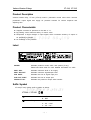
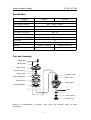
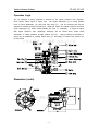
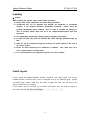
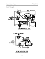
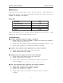
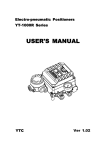
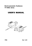
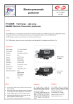
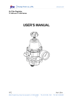
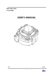
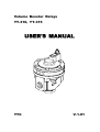
Volume Booster Relays YT-310, YT-315 USER'S MANUAL YTC V.1.01 V olume Booster R elays Y T-310, Y T-315 Product Description Volume booster relay, YT-310 (YT-315) used in pneumatic control valve which receives positioner's output signal and supply air pressure actuator for reduce response and adjusting time. Product Characteristic z Supplies constant air pressure at the rate of 1:1. z By-passing control enhance safety of control valve. z Responses to slight changes in input signal, which increases accuracy of output of air pressure to actuator. z No leakeage of air pressure. Label MODEL: Indicates product's model, suffix, and options (if any). Please see below table for more detailed information on suffix. MAX. SUP: Indicates maximum level of air supply. MAX. SIG./OUT: Indicates maximum signal/output level. SIG. PORT: Indicates the size of signal input port. SUP./OUT PORT: Indicates the size of output port. PRODUCT NO.: Indicates the product's unique serial number. Suffix Symbol YT-310(YT-315) follows suffix symbols as below. YT-310 / YT-315 Connection Size P : PT N : NPT Ambient Temperature 1 : -20 ~ 70℃ 2 : -20 ~ 120℃ 3 : -40 ~ 70℃ - 1 - V olume Booster R elays Y T-310, Y T-315 Specification Category YT-310 YT-315 Max Supply Pressure Max. 10.2kgf/㎠ (142psi) Max Output Pressure Max. 7.1kgf/㎠ (100psi) In/ Output Pressure Ratio 1 : 1 Flow Capactiy (Cv) 4.98 In/ Output Connection NPT 3/4 Signal Connection NPT 1/4 Linearity ±1% (F.S.) Hysteresis 1% Ambient Temp -20~70℃(St'nd), -20~120℃(High), -40~70℃(Low) Material Aluminum Dicasting Stainless Steel 316 Weight 2.3kg 5.0kg Part and Assembly Adjust Bolt M8x40 Bollt Upper Cover Balance Spring Spring Seat Exhaust Disk Upper Diaphragm Main Seat Exhaust Ring Base Body Lower Diaphragm Stem Main Disk Stem Spring Drain Plug Please be knowledgeable of product's major parts and assembly steps for future maintenance. - 2 - V olume Booster R elays Y T-310, Y T-315 Operation Logic The air pressure is being supplied to actuator by the supply pressure from regulator, which sends output signal to signal port. The upper diaphragm (③) is being pushed down to lower diaphragm (⑤) and push main disk (⑨). The air pressure then will be supplied to actuator through exhaust port. Balanced output and signal pressure will move upper diaphragm (③) which would maintain the rate 1:1 constantly. If output is higher than signal pressure, then diaphragm assembly will be raised which would result exhaustion of output pressure through exhaust ring (④). Output pressure's sensitivity to signal can be adjusted by rotating adjust bolt (①), and safety of closed loop system can be enhanced. Dimension (outer) - 3 - V olume Booster R elays Y T-310, Y T-315 Installing ☞ Caution When installing the product, please follow below procedures. z Always wear safety equipments and follow safety procedures. z Compressed gas can be exploded and damage the body/parts or surrounding structure, if the product's maximum specification exceeded. product's specification before installing. Please check the Also, in order to minimize the damage, in case of accident, please make sure all of the compressed/pressurized input lines by-passed. z For maintenance, please stop volume booster's operation timely basis. z A must be clean, dry, and not corrosive gas which must be passed through the filter. z Inflow air will be exhausted through the exhaust port which located on the side of the volume booster. z Please be check exhaust port for substances or obstacle. Also, make sure not to leave volume booster in sealed places. z It is recommended to use appropriate capacity of air filter regulator. Install Layout YT-310 should be installed between actuator, positioner, and supply pipes, and can be installed without a bracket which can be supported only by air pressure pipes. Before connecting pipes, please make sure the inside of pipes are clear, and the size of the pipe are relevant to the capacity. If the booster must be mounted on a bracket, the bracket must be made according to the outer dimension on the previous page. - 4 - V olume Booster R elays Y T-310, Y T-315 Install Example - 5 - V olume Booster R elays Y T-310, Y T-315 Maintenance Please refer to below table (repair kit) and parts name (pg 2). Before replacing any parts, please make sure to follow field's safety instruction and manual to avoid any accidents and damages to the product. Repair Kit Part Name Qty Upper Diaphragm 1 (ea) Lower Diaphragm 1 (set) Stem Assembly 1 (set) O-Ring 2 (ea) When using Repair Kit, all of the parts must be replaced at the same time. Partial replacing part may result shortening product's life cycle. Troubleshooting ▶ No valve operation response to signal to positioner ① Please check if air pressure supplied is constant and normal from regulator to positioner and/or volume booster. ② Please check if air pressure is being exhausted from positioner's exhaust ③ Please check if supply and exhaust port are being not blocked. ▶ Unstable valve operation when signal has been sent to positioner ① Please reduce valve packing and/or valve friction level. ② Please increase size of the actuator. ▶ Hunting occurs when signal has been sent to positioner ① Please reduce valve packing and/or valve friction level. ② Please increase size of the actuator. ③ Please rotate control screw counter-clockwise on top of the booster to reduce sensitivity. ▶ Slow valve operation when signal has been sent to positioner ① Please check if regulator control pressure is too low. ② Please check if supply pipe to actuator is blocked. ③ Please check if there is any leakage. ④ Please rotate control screw clockwise on top of the booster to enhance sensitivity. - 6 - port. Manufacturer Warranty z For the safety, it is imperative to follow install instruction in the manual. It is not manufacturer's responsibility for any damages due to the user's negligence. z It is not manufacturer's responsibility for any damages or accident due to user's alteration of the product and parts. If alteration or modification is necessary, please contact the manufacturer directly. z Manufacturer warrants the product from the date of original retail purchase of the product for one (1) year, except as otherwise stated. z Manufacturer warranty will not cover the products that the product have been subjected to abuse, accident, alteration, modification, tampering, negligence, misuse, faulty installation, lack of reasonable care, repair or service in any way that is not contemplated in the documentation for the product, or if the model or serial number has been altered, tampered with, defaced or removed; damages that occurs in shipment, due to act of God, failure due to power surge, and cosmetic damage. Improper or incorrectly performed maintenance or report voids this Limited Warranty. z For detailed warranty information, please contact the corresponding local Young Tech Co., Ltd office or headquarter office in South Korea. Young Tech Co., Ltd Address : #662-8 Pungmu-Dong, Gimpo-City, Kyunggi-Do, South Korea Telephone: +82-31-986-8545 Fax: +82-31-986-2683 Website: http://www.ytc.kr User Manual and other information on the documents are subjected to change without any notice. Please visit website for most updated information. Printed Date: June, 2007