1
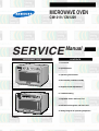
MICROWAVE OVEN
CM1219 / CM1229
SERVICE
Manual
CONTENTS
MICROWAVE OVEN
1. Precaution
2. Specifications
3. Operating Instructions
4. Disassembly and Reassembly
5. Alignment and Adjustments
6. Troubleshooting
P
1
2
3
4
5
6
7
8
9
0
+ 20sec
7. Exploded Views and Parts List
8. PCB Circuit Diagrams and Parts List
9. Wiring Diagram & Operating Sequence
SESC
PRECAUTIONS TO BE OBSERVED BEFORE AND
DURING SERVICING TO AVOID POSSIBLE
EXPOSURE TO EXCESSIVE MICROWAVE ENERGY
(a) Do not operate or allow the oven to be
operated with the door open.
(b) Make the following safety checks on all
ovens to be serviced before activating
the magnetron or other microwave
source, and make repairs as
necessary:
(1) Interlock operation,
(2) proper door closing,
(3) seal and sealing surfaces (arcing,
wear, and other damage),
(4) damage to or loosening of hinges
and latches,
(5) evidence of dropping or abuse.
(c) Before turning on microwave power for
any service test or inspection within the
microwave generating compartments,
check the magnetron, wave guide or
transmission line, and cavity for proper
alignment, integrity, and connections.
(d) Any defective or misadjusted
components in the interlock, monitor,
door seal, and microwave generation
and transmission systems shall be
repaired, replaced, or adjusted by
procedures described in this manual
before the oven is released to the
owner.
(e) A microwave leakage check should be
performed on each oven prior to
release to the owner.
Samsung Electronics
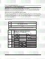
1. Precaution
Follow these special safety precautions. Although the microwave oven is completely safe during ordinary
use, repair work can be extremely hazardous due to possible exposure to microwave radiation, as well as
potentially lethal high voltages and currents.
1-1 Safety precautions (
)
1. All repairs should be done in accordance
with the procedures described in this
manual.
2. Microwave emission check should be
performed prior to servicing if the oven is
operative.
3. If the oven operates with the door open :
Instruct the user not to operate the oven and
contact the manufacturer and the centre for
devices and radiological health immediately.
4. Notify the Central Service Centre if the
microwave leakage exceeds 5 mW/cm2.
13. Design Alteration Warning:
Use exact replacement parts only, i.e.,
only those that are specified in the
drawings and parts lists of this manual.
This is especially important for the
Interlock switches. Never alter or add to
the mechanical or electrical design of the
microwave oven. Any design changes or
additions will void the manufacturer's
warranty.
14. Always unplug the unit's AC power cord
from the AC power source before
attempting to remove or reinstall any
component or assembly.
5. Check all grounds.
6. Do not power the microwave oven from a "2prong" AC cord. Be sure that all of the builtin protective devices are replaced. Restore
any missing protective shields.
7. When reinstalling the chassis and its
assemblies, be sure to restore all protective
devices, including: nonmetallic control knobs
and compartment covers.
8. Make sure that there are no cabinet
openings through which people--particularly
children--might insert objects and contact
dangerous voltages. Examples: Lamp hole,
ventilation slots.
9. Inform the manufacturer of any oven found
to have emmission in excess of 5mW/cm2.
Make repairs to bring the unit into
compliance at no cost to owner and try to
determine cause.
Instruct owner not to use oven until it has
been brought into compliance.
10. Service technicians should remove their
watches while repairing an microwave oven.
11. To avoid any possible radiation hazard,
replace parts in accordance with the wiring
diagram. Also, use only the exact
replacements for the following parts:
Primary and door sensing switches, interlock
monitor switch.
12. If the fuse is blown by the Interlock Monitor
Switch: Replace all of the following at the
same time: Primary and door sensing
switches, as well as the Interlock Monitor
Switch. The correct adjustment of these
switches is described elsewhere in this
manual. Make sure that the fuse has the
correct rating for the particular model being
repaired.
Samsung Electronics
15. Never defeat any of the B+ voltage
interlocks. Do not apply AC power to the
unit (or any of its assemblies) unless all
solid-state heat sinks are correctly installed.
16. Some semiconductor ("solid state") devices
are easily damaged by static electricity.
Such components are called
Electrostatically Sensitive Devices (ESDs).
Examples include integrated circuits and
field-effect transistors.
Immediately before handling any
semiconductor components or assemblies,
drain the electrostatic charge from your
body by touching a known earth ground.
17. Always connect a test instrument's ground
lead to the instrument chassis ground before
connecting the positive lead; always
remove the instrument's ground lead last.
18. When checking the continuity of the switches
or transformer, always make sure that the
power is OFF, and one of the lead wires is
disconnected.
19. Components that are critical for safety are
indicated in the circuit diagram or parts
list by shading,
or
.
20. Use replacement components that have the
same ratings, especially for flame resistance
and dielectric strength specifications. A
replacement part that does not have the
same safety characteristics as the original
might create shock, fire or other hazards.
1
Precaution
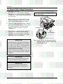
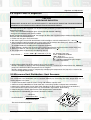
1-2 Special High Voltage Precautions
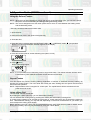
1. High Voltage Warning
Do not attempt to measureany of the high
voltages--this includes the filament voltage of
the magnetron. High voltage is present during
any cook cycle.
Discharge the 2 High Voltage Capacitors
before servicing !
Before touching any components or wiring,
always unplug the oven and discharge the
high voltage capacitor (See Figure here)
2. The high-voltage capacitor remains charged
about 30 seconds after disconnection. Short
the negative terminal of the high-voltage
capacitor to the oven chassis. (Use a
screwdriver.)
3. High voltage is maintained within specified
limits by close-tolerance, safety-related
components and adjustments. If the high
voltage exceeds the specified limits, check
each of the special components.
Screwdriver
H.V.Capacitors
Negative Terminal
PRECAUTION
There exists HIGH VOLTAGE ELECTRICITY
with high current capabilities in the circuits of
the HIGH VOLTAGE TRANSFORMER
secondary and filament terminals. It is
extremely dangerous to work on or near these
circuits with the oven energized.
DO NOT measure the voltage in the high
voltage circuit including filament voltage of
magnetron.
Note :Touch chassis side first then short to
the high voltage capacitor terminal by
using a screwdriver.
PRECAUTION
Never touch any circuit wiring with your hand
nor with an insulated tool during operation.
PRECAUTION
Servicemen should remove their watches
whenever working close to or replacing the
magnetron.
2
Samsung Electronics
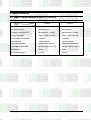
2. Specifications
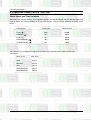
2-1 Table of Specifications (CM1219 / CM1229)
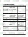
ITEM
MODEL
CM1219
CM1229
TIMER
Max. 25 min
Max. 25 min
POWER SOURCE
230V/50HZ, AC
230V/50HZ, AC
POWER CONSUMPTION
MICROWAVE : 2,200W
MICROWAVE : 2,200W
OUTPUT POWER
230V: 1,200W (IEC-705)
230V: 1,200W (IEC-705)
OPERATING FREQUENCY
2,450MHz
2,450MHz
MAGNETRON
OM75P(20)ESS
OM75P(20)ESS
COOLING METHOD
VENTILATION MOTOR
VENTILATION MOTOR
OUTSIDE DIMENSIONS
464(W) x 368(H) x 557(D)
464(W) x 368(H) x 557(D)
NET WEIGHT
32 Kg
32 Kg
SHIPPING WEIGHT
34.5 Kg
34.5 Kg
Samsung Electronics
3
3. Operating Instructions
3-1 Features (CM1219)
VARIABLE COOKING POWER CONTROL DIAL
TIMER DIAL
OVEN LAMP (230V 25W)
+20sec PAD
DISPLAY
STOP/CANCEL PAD
OVEN LAMP COVER
START BUTTON
DOOR HANDLE
CEILING COVER
SAFETY INTERLOCK
HOLES
DOOR
DOOR LATCHES PLATE TRAY
AIR FILTER
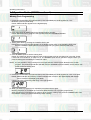
3-2 Features (CM1229)
CONTROL PANEL
OVEN LAMP (230V 25W)
+20sec PAD
DISPLAY
OVEN LAMP COVER
STOP/CANCEL PAD
P
1
2
3
4
5
6
7
8
9
0
+ 20sec
DOOR HANDLE
START BUTTON
CEILING COVER
SAFETY INTERLOCK
HOLES
DOOR
DOOR LATCHES
4
PLATE TRAY
AIR FILTER
Samsung Electronics
Operating Instructions
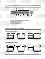
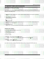
3-3 Control Panel (CM1229)
1
2
4
1
P
2
3
4
5
6
7
8
9
0
+ 20sec
3
5
6
7
8
9
10
1. DISPLAY
2. PROGRAM PAD
3. PROGRAM LOCK PAD
4. NUMBER PADS(TIME, MEMORY PROGRAMMING)
5. POWER LEVEL SELECTOR PAD
6. DEFROST SELECTOR PAD
7. DOUBLE QUANTITY PAD
8. +20sec PAD (ONE TOUCH COOK PAD)
9. STOP/CANCEL PAD
10. START BUTTON
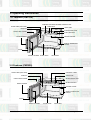
3-4 External Views (CM1219 / CM1229)
3-4-1 External Views (CM1219)
43
557
530
26
1000
368
464
10
444
486
514
3-4-2 External Views (CM1229)
43
557
530
26
1000
368
464
10
444
Samsung Electronics
486
514
5
Operating Instructions
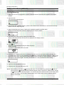
3-5 Operation Guide (CM1219)
Cooking/Reheating
1. Make sure the oven is plugged into a properly earthed electrical outlet and ‘ON’ appears in the display
window.
2. Open the door.
The oven lamp will be turned on.
3. Put the food into a suitable container, place it in the center of the oven and then close the door securely.
Result: The oven lamp will go off.
4. Select the desired power level by rotating the COOKING POWER CONTROL DIAL.
Result: The selected power level will be displayed in the display window.
5. Set the desired heating time by rotating the TIMER DIAL.
Result: “ON” blinks and the selected time is displayed in the display window.
6. Press
pad:
Result:The oven lamp and cooling fan will be turned on.
Heating will start.
The time on digital display will count down.
7. When all time is elapsed, the end of cycle Beep Tone will sound 4 times and all heating will stop. The
oven lamp will go off. For 1 min, the display shows and the cooling fan will keep working in order to cool
down the interior parts. During the time, the fan will not stop even when you open the door. 1 min later it
will stop and ON appears again. Food may be removed from oven whilst the fan is still running.
8. Open the door and take the food out.
9. Close the door. The oven lamp will go off.
NOTE: Whilst heating, one press on
pad stops the oven. You can restart it by pressing the
pad or a
second press on
pad will cancel the selected program. When it is NOT in a heating cycle, one tap
on
pad cancels the selected program. You can set the power level first and then the cooking time
next, or vice versa. You can press +20sec button one or more times in order to add the cooking
time by 20 seconds.
6
Samsung Electronics
Operating Instructions
3-5 Operation Guide (CM1219 continued)
To stop the cooking
You can stop cooking at any time so that you can:
• Check the food
• Turn the food over or stir it
• Leave it to stand
* Temporarily ; Open the door or press
button once.
Result: Cooking stops. To resume cooking, close the door and press
again.
* Completely ; Press the
button twice.
Result: The cooking settings are cancelled.
If you want to cancel any cooking settings before starting cooking, simply press
once.
Using the Defrost Feature
The Defrost feature enables you to defrost meat, poultry, fish.
NOTE: Only use containers that are microwave-safe.
1. Open the door.
2. Place the frozen food in the centre of the plate tray.
3. Close the door.
4. Rotate the Variable Cooking Power Control dial to the DEFROST HIGH(
you wish.
Result: The DEFROST indicator appears on the digital display.
) or DEFROST LOW(
) as
5. Rotate the TIMER dial to set the defrosting time.
The Maximum time that can be set under defrosting mode is 50min.
6. Press
button.
Result: Defrosting begins.
Samsung Electronics
7
Operating Instructions
3-5 Operation Guide (CM1229)
Cooking/Reheating
NOTE: When you first plug in the power cord, the oven beeps once and all the indicators show for 5 sec in
the display window.
NOTE: When heating cycle is completed and you open the door, the oven lamp automatically turns on and
goes off 1 min later.
NOTE: When you open the door whilst in a heating cycle, the oven stops operating and the oven lamp
automatically turns on for 1 min and goes off 1 min later. If you leave the oven door open for more
than 1 min, the oven beeps once every minute and after 5 min the power source check indicator
‘ON’ appears in the display window.
This oven is preset at the factory for automatic operation.
1. Make sure the oven is plugged into a properly earthed electrical outlet and ‘ON’ appears in the display
window.
2. Open the door.
The oven lamp will be turned on.
3. Put the food into a suitable container, place it in the centre of the oven and then close the door securely.
Result: The oven lamp will go off.
4. Select the desired power level by pressing the Power Level Selector pad.
Result: The selected power level will be displayed in the display window.
5. Set the desired heating time by pressing the Number pads.
Result: The selected time is displayed in the display window.
6. Press START button:
Result: The oven lamp and cooling fan will be turned on. Heating will start. The time on digital display
will count down.
7. When all time is elapsed, the end of cycle Beep Tone will sound 4 times and all heating will stop. The
oven lamp will go off. For 1 min, the display shows and the cooling fan will keep working in order to
cool down the interior parts. During the time, the fan will not stop even when you open the door. 1 min
later it will stop and ‘ON’ appears again. Food may be removed from oven whilst the fan is still running.
8. Open the door and take the food out.
9. Close the door. The oven lamp will go off.
8
Samsung Electronics
Operating Instructions
3-5 Operation Guide (CM1229 continued)
Using the Defrost Feature
NOTE: When the oven was operating for longer than 25 min under Defrosting cycle, you can NOT change
the power level from Defrosting to Heating(Cooking/Reheating) mode.
NOTE: The oven is designed not to work when power level is set to ‘0’ mode between the heating mode
and the defrosting mode.
* Use only containers that are microwave-safe.
1. Open the door.
2. Place the frozen food in the centre of the plate tray.
3. Close the door.
4. Press the Defrost selector pad to set DEFROST HIGH (
) or DEFROST LOW (
Result: The selected DEFROST indicator appears in the display.
) as you wish.
5. Press the Number pads to set the defrosting time. (Max. 50 min)
6. Press
button.
Result: Defrosting begins.
NOTE: It is not possible to set a defrosting time for longer than 50min. The defrost indicator will flash and it
is advisable to press CANCEL and enter a new defrost level and time.
Repeat Feature
You can repeat the previous cooking setting (regardless of manual or automatic memory heating) by
pressing the START button. The oven starts with exactly the same heating time and power level that were
used in the last operation.
NOTE: Repeat feature does not support for +20sec pad. The repeat feature will be cancelled once the
power source is cut off.
Using +20sec Pad
This is a ONE TOUCH COOK pad.
By touching the +20sec pad once, you can start heating instantly.
You can increase the cooking time by pressing the +20sec pad while heating is being done.
A cooking time increases by 20 seconds at each press on +20sec pad. But it can not exceed the maximum
time. Like traditional cooking, you may find that, depending on the food’s characteristics or your tastes, you
have to adjust the cooking times slightly.
Before operating the oven, times can be increased/decreased using either the time pads or +20sec button.
During the operating, time may only be added by using the +20sec button.
Samsung Electronics
9
Operating Instructions
3-5 Operation Guide (CM1229 continued)
Memory Pads Programming
1. Hold down PROGRAM LOCK pad and then press PROGRAM pad. Hold together for 2 sec.
Be sure to press the pads firmly.
Result: PROG indicator appears in the digital display.
2. Press appropriate NUMBER pad for the desired memory number.
Result: Selected memory program code appears below the PROGRAM indicator.
3. Select power level by pressing the POWER LEVEL pad.
Result:Default power level HIGH appears in the display at first press of the POWER LEVEL pad.
Press the POWER LEVEL pad one or more times until you get the desired power level.
4. Press NUMBER pads to set the cooking time.
Result: The maximum time according to each cooking power level can be referred to in the title “Power
Levels and Time Variations” on page 12~13. The NUMBER pads will not operate or respond when you
press a cooking time exceeding the maximum value.
NOTE: It is not possible to set a cooking time for longer than the maximum time allowed on the chosen
program. The power level indicator will flash and it is advisable to press CANCEL and to enter a new
power level and cooking time.
5. Hold down PROGRAM LOCK pad and then press PROGRAM pad. Hold together for 2 sec once again.
Result: PROG indicator and memory number indicator blink 3 times in the digital display with a beep
sound. And then the display goes blank.
Caution: Be sure to press the pads firmly in the right position.
6. When you want to program more, repeat the procedures above again.
Memory programs are available up to 30 items. Make sure the unit is properly programmed.
After programming is finished, all you have to do for memory cooking is to press the NUMBER pad. Then
the selected memory program automatically starts cooking.
10
Samsung Electronics
Operating Instructions
3-5 Operation Guide (CM1229 continued)
How to Operate Memory Cooking
After having finished memory programming, just press the NUMBER pad of the memory number you want to
select. The oven will automatically start heating according to the pre-programmed cooking time and power
level after a short delay (5 sec).
1. Make sure the oven is plugged into a properly earthed electrical outlet and ‘ON’ appears in the display
window.
2. Open the door.
The oven lamp will be turned on.
3. Put the food into a suitable container, place it in the centre of the oven and then close the door securely.
Result: The oven lamp will go off.
4. Press NUMBER pad.
Result: After 2 seconds, the selected memory program automatically starts heating.
Stopping the Cooking
You can stop cooking at any time so that you can:
• Check the food
• Turn the food over or stir it
• Leave it to stand
To stop the cooking;
* Temporarily: Open the door or press
pad once.
Result: Cooking stops. To resume cooking, close the door and press
again.
* Completely: Press the
pad twice.
Result: The cooking settings are cancelled.
If you want to cancel any cooking settings before starting cooking, simply press CANCEL pad once.
Samsung Electronics
11
Operating Instructions
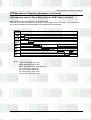
3-5 Operation Guide (CM1219 / CM1229)
Power Levels and Time Variations
The power level function enables you to adapt the amount of energy dissipated and thus the time required to
cook or reheat your food, according to its type and quantity. You can choose between the power levels
below.
.....................................................................................................................................................
Power Level
Percentage
CM1219/1229
.....................................................................................................................................................
HIGH(
)
MEDIUM(
LOW(
)
)
HIGH DEFROST(
)
100%
1200W
70%
840W
50%
600W
30%
360W
LOW DEFROST(
)
15%
180W
.....................................................................................................................................................
You cannot set the cooking time longer than maximum value allowed to each specific power level.
(see below.)
..................................................................
Power Level
Max. Time
..................................................................
HIGH
25 min.
MEDIUM
40 min.
LOW
40 min.
HIGH DEFROST
50 min.
LOW DEFROST
50 min.
..................................................................
12
Samsung Electronics
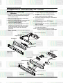
4. Disassembly and Reassembly
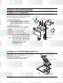
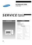
4-1 Replacement of Magnetron
Remove the magnetron including the shield case,
permanent magnet, choke coils and capacitors (all
of which are contained in one assembly).
Duct-MGT-L
Nut-Flange
1. Remove the outer panel.
NOTE: Before servicing, make sure to discharge
electric charge remaining on the high
voltage capacitors or wait for more than 5
min.
2. Remove the back cover.
3. Disconnect all lead wires from the magnetron.
4. Remove screws securing the duct-MGT and
duct-fan.
5. Remove the nut-flanges securing the
magnetron by using a box wrench.
6. Take out the magnetron very carefully.
NOTE1: When removing the magnetron, make
sure that its antenna does not hit any
adjacent parts, or it may be damaged.
NOTE2: When replacing the magnetron, be
sure to remount the magnetron gasket
in the correct position and make sure
the gasket is in good condition.
(See page 19 for adjustment
instructions.)
Duct-Fan
DuctMGT-R
Magnetron
4-2 Replacement of High Voltage Transformer
1. Discharge the high voltage capacitor.
2. Disconnect all the leads.
3. Remove the mounting bolts securing the HVT.
4. Reconnect the leads correctly and firmly.
H. V. Trans
LVT
Samsung Electronics
4 Mounting Bolts
13
Disassembly and Reassembly
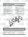
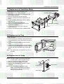
4-3 Replacement of Door Assembly
4-3-1 Removal of Door Assembly
4-3-2 Removal of Door Handle
NOTE: Be sure to wear gloves when you
disassemble or assemble the parts.
1. Remove hex bolts securing the upper hinge
and lower hinge. Then remove the door
assembly.
2. Insert the flat screwdriver or thin metal plate
into the gap between the door E and door C to
remove Door C from the door assembly.
NOTE: Be careful when handling Door C as is
fragile.
NOTE: The thickness of the flat screwdriver or
thin metal plate inserted into the gap
should be 0.5mm or less.
3. Remove 2 screws securing the Door Handle to
the Door E Ass’y.
4. Unbend the 2 metal tabs at both ends of the
Door Handle to remove the Door Handle Cover
from the Door Handle.
1. Remove hex bolts securing the upper hinge
and lower hinge. Then remove the door
assembly.
2. Insert the flat screwdriver or thin metal plate
into the gap between the door E and door C to
remove Door C from the door assembly.
3. Remove 2 screws securing the Door Handle.
4. Unbend the 6 metal tabs around the trim of
Decoration Door Cover.
5. Remove 3 screws securing the Door E Ass’y.
6. Remove upper hinge and lower hinge.
7. Remove Decoration Door, Screen B, Key-Door,
Spring-Key, Pin-Key as needed.
Door C
Upper Hinge
Door E Ass’y
Decoration Door
Screen B
Decoration Door Cover
2 screws securing
Door Handle
Lower Hinge
Spring-Key
Door Handle Cover
Key-Door
Pin-Key
Door Handle
4-3-3 Reassembly Test
After replacement of the defective component parts of the door, reassemble it and follow the
instructions below for proper installation and adjustment so as to prevent an excessive microwave
leakage.
1. When mounting the door to the oven, be sure to adjust the door parallel to the bottom line of the oven face
plate by moving the upper hinge and lower hinge in the direction necessary for proper alignment.
2. Adjust so that the door has no play between the inner door surface and oven front surface. If the door
assembly is not mounted properly, microwave energy may leak from the space between the door and oven.
3. Do the microwave leakage test.
14
Samsung Electronics
Disassembly and Reassembly
4-4 Replacement of Fuse and H.V.Fuse
1. Disconnect the oven from the power source.
2. Remove defective fuse from Noise filter.
3. When replacing the fuse, be sure to use an
exact replacement part. If new fuse blows out
again after replacement, check the primary
interlock switch, door sensing switch and
interlock monitor switch.
4. When the above three switches operate
properly, check if any other part such as the
control circuit board, ventilation motor or high
voltage transformer is defective.
1.6A Fuse
10A Fuse
H.V.Fuse
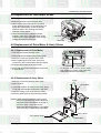
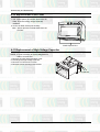
4-5 Replacement of Drive Motor & Ass’y Stirrer
4-5-1 Replacement of Drive Motor
P
1
2
3
4
5
6
7
8
9
0
+ 20sec
1. Remove outer panel and back-cover.
2. Disconnect all the lead wires from the drive motor.
3. Remove a screw securing the drive motor.
4. When replacing the drive motor, be sure to
remount it in the correct position with the coupler.
5. Connect all the leads to the drive motor.
6. Screw the drive motor to the bracket motor with
a screw driver.
To remove Ass’y Stirrer Cover: Hold
side stoppers of ceiling cover with both
hands and pull them in and down.
4-5-2 Replacement of Ass’y Stirrer
1. Remove a screw securing the drive motor.
2. Open the door.
Screw
Drive Motor
3. Hold side stoppers of ceiling cover (Ass’y Stirrer
Cover) with both hands and pull them in and down.
4. Take the ceiling cover out of the oven cavity.
5. Remove plastic clips securing the Ass’y Stirrer.
Caution: When removing the Ass’y Stirrer Cover,
be sure to be extremely careful about the
exposed inside components on the top of
the oven cavity. If any of them are
deformed, abnormal symptom can happen
such as arcing or sparks during operation.
Ass’y Stirrer
Ass’y Stirrer Cover
Plastic Clips
Samsung Electronics
15
Disassembly and Reassembly
4-6 Replacement of Control Box Ass’y and P.C.Board
6. Remove Control Box Ass’y.
7. To replace Digitron, remove 2 screws securing
the PCB4.
8. To replace Start Button Circuitry, remove 3
screws securing the PCB3. (CM1229)
9. Unbend the metal tabs holding the Panel-Base
to Control Box body.
4-6-1 Removal of Control Box
Assembly
1. Be sure to discharge any static electric charge
built up on your body and avoid touching the
touch control circuitry.
2. Remove 3 screws securing the Control Box
Ass’y to the oven cavity.
3. Disconnect all the lead wires, connectors and
ground taping (CM1229) from the main
control circuit board (PCB1).
4. Lift up the FPC connector hooks about 5mm
upward which connects to the main control
circuit board (PCB1) from the tail of switch
membrane of the control box assembly.
(CM1229)
5. Remove a screw securing the tapped taping to
PCB1. (CM1229)
4-6-2 Removal of main P.C.Board
1. Remove Control Box Assembly by following the
steps 1~ 5 at left.
2. Remove 4 screws securing the main PCBoard
to the bracket PCBoard.
NOTE: When handling the the touch control
circuitry, be most careful to avoid damage.
Wire Harness-B
Main P.C.Board (PCB1)
Wire Harness-C
Digitron(PCB4)
Panel-Base
Wire Harness-D
PCB2
Button-Select
Button-Start
Main P.C.Board
(PCB1)
Control Box Ass’y
(CM1219)
Wire Harness-C
Digitron(PCB4)
Panel Base
Wire Harness-B
Wire Harness-F
Window-Display
Cover Panel
PCB3
Cover-Panel/L
Switch-Membrane
Control Box Ass’y
(CM1229)
16
Cover-Panel/R
Samsung Electronics
Disassembly and Reassembly
4-7 Replacement of Ventilation Motor
1. Remove the outer panel and back-cover.
2. Discharge the high voltage capacitor.
3. Remove all the lead wires from Magnetron and
High Voltage Capacitor.
4. Remove 2 screws securing the duct fan.
5. Remove 2 screws securing the Supporter-FanMount.
6. Lift the Ventilation Motor Ass’y slightly upward
and pull it out.
7. Remove lead wires and connectors.
8. Remove a screw securing the C-Film to the
Supporter-Fan-Mount.
9. Turn the fan motor ass’y over so that the
bracket side is up.
10. Remove 4 screws securing the Ventilation Motor.
Ventilation Motor
C-Film
Supporter-Fan-Mount
Duct-Fan
4-8 Replacement of Tray
1. Open the door.
2. Remove the tray by inserting a thin metal tool into
the gap between the oven wall and the tray silicon
cover.
3. Insert the new tray by tilting it across the oven
cavity.
4. Firstly fix the front part (refers to the place where
the silicon cover is thinner than the other 3 edges)
and then place the backward part carefully and
firmly.
NOTE: Be careful when you handle the tray since it
is fragile.
Tray
4-9 Replacement of Lamp
NOTE: You don’t need to remove the outer panel
or other parts in order to replace a lamp.
1. Remove a screw securing the lamp cover.
2. Remove the lamp by rotating it clockwise.
3. Replace with a new lamp by rotating it counterclockwise.
NOTE : If it is necessary to replace the lamp
holder, you can disconnect lead wires by
pushing down on the hole of lead wires
using a long pointed tool.
Samsung Electronics
Lamp Cover
Lamp Holder
Outer Panel
17
Disassembly and Reassembly
4-10 Replacement of Air Filter
1. Pull out the spacer pins at both ends of the Air
Filter. Then the locking clamps inside are
released.
2. Lift the Air Filter off the post carefully.
Note: Spacer pins are not detachable from the
Air Filter.
Plastic Spacer Pins
4-11 Replacement of High Voltage Capacitor
NOTE: It is not necessary to remove Magnetron in
order to remove HVC.
1. Remove the outer panel and back cover.
2. Discharge the high voltage capacitor.
3. Remove HVT wire and H.V.Fuse.
4. Remove screws securing HVC bracket.
H.V.Capacitor
18
Samsung Electronics
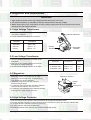
5. Alignment and Adjustments
PRECAUTION
1. High voltage is present at the high voltage terminals during any cook cycle.
2. It is neither necessary nor advisable to attempt measurement of the high voltage.
3. Before touching any oven components or wiring, always unplug the oven from its power source and
discharge the high voltage capacitor.
5-1 High Voltage Transformer
1. Remove connectors from the transformer terminals
and check continuity.
2. Normal resistance readings are as follows:
Terminal
Secondary
Filament
Primary
Filament Terminals
Resistance
Approx. 98Ω
Approx. 0Ω
Approx. 1.3Ω
Primary
Terminals
Secondary
Terminal
(Room temperature = 20˚C)
5-2 Low Voltage Transformer
1. The low voltage transformer is located on the
base plate.
2. Remove the low voltage transformer from the
base plate and check continuity.
3. Normal resistor reading is shown in the table.
Terminals
Resistance
Wire
1~2(input)
3~4(output 20V)
5~6(output 3.2V)
Approx. 296Ω
Approx. 5.1Ω
Approx. 1.1Ω
WHT
RED
YEL
5-3 Magnetron
Continuity checks can indicate only an open
filament or a short magnetron. To diagnose an
open filament or short magnetron :
1. Isolate the magnetron from the circuit by
disconnecting its leads.
2. A continuity check across the magnetron filament
terminals should indicate one ohm or less.
3. A continuity check between each filament terminal
and magnetron case should read open.
Magnetron Antenna
Gasket
Plate
Cooling Fins
5-4 High Voltage Capacitor
1. Check continuity of the capacitor with the meter set at the highest resistance scale.
2. Once the capacitor is charged, a normal capacitor shows continuity for a short time, and then indicates 9MΩ.
3. A shorted capacitor will show continuous continuity.
4. An open capacitor will show constant 9MΩ.
5. Resistance between each terminal and chassis should read infinite.
Samsung Electronics
19
Alignment and Adjustments
5-5 High Voltage Diode
1. Isolate the diode from the circuit by disconnecting its leads.
2. With the ohm-meter set at the highest resistance scale, measure across the diode terminals. Reverse the
meter leads and read the resistance. A meter with 6V, 9V or higher voltage batteries should be used to
check the front-to back resistance of the diode (otherwise an infinite resistance may be read in both
directions). The resistance of a normal diode will be infinite in one direction and several hundred KΩ in the
other direction.
5-6 Main Relay and Power Control Relay
1. The relays are located on the PCB Ass'y. Isolate them from the main circuit by disconnecting the leads.
2. Operate the microwave oven with a water load in the oven. Set the power level to high.
3. Check continuity between terminals of the relays after Start pad is pressed.
5-7 Adjustment of Primary, Door Sensing and Monitor Switch
Precaution
For continued protection against radiation
hazard, replace parts in accordance with the
wiring diagram and be sure to use the correct
part number for the following switches: Primary
and door sensing switches, and the interlock
monitor switch (replace all together). Then
follow the adjustment procedures below. After
repair and adjustment, be sure to check the
continuity of all interlock switches and the
interlock monitor switch.
Latch-Body
Door Sensing S/W
Lever-Switch/U
Interlock Monitor S/W
Primary S/W
1. When mounting Primary switch and Interlock
Monitor switch to Latch Body, consult the figure.
NOTE:No specific adjustment during installation
of Primary switch and Monitor switch to the latch
body is necessary.
2. When mounting the Latch Body to the oven
assembly, adjust the Latch Body by moving it so
that the oven door will not have any play in it.
Check for play in the door by pulling the door
assembly. Make sure that the latch keys move
smoothly after adjustment is completed.
Completely tighten the screws holding the Latch
Body to the oven assembly.
3. Reconnect to Monitor switch and check the
continuity of the monitor circuit and all latch
switches again by following the components test
procedures.
4. Confirm that the gap between the switch housing
and the switch actuator is no more than 0.5mm
when door is closed.
20
Lever-Switch/L
Primary S/W
Interlock Monitor S/W
NC
COM
NO
WHT
BRN
COM
COM
NO
BRN/ORG
BLU
COM
RED/YEL
NO
WHT
PINK/PINK
NC
RED/WHT
NO
BRN
BRN/AZR
Primary S/W
Monitor S/W(COM-NC)
Monitor S/W(COM-NO)
Door Sensing S/W
Door Sensing S/W
COM
NO
ORG
ORG
Door Open Door Closed
∞
0
0
∞
∞
0
∞
0
Samsung Electronics
Alignment and Adjustments
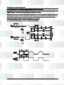
5-8 Output Power of Magnetron
CAUTION
MICROWAVE RADIATION
PERSONNEL SHOULD NOT ALLOW EXPOSURE TO MICROWAVE RADIATION FROM MICROWAVE
GENERATOR OR OTHER PARTS CONDUCTING MICROWAVE ENERGY.
The output power of the magnetron can be measured by performing a water temperature rise test.
Equipment needed :
* Two 1-liter cylindrical borosilicate glass vessel (Outside diameter 190 mm)
* One glass thermometer with mercury column
NOTE: Check line voltage under load. Low voltage will lower the magnetron output. Make all temperature and
time tests with accurate equipment.
1. Fill the one liter glass vessel with water.
2. Stir water in glass vessel with thermometer, and record glass vessel's temperature ("T1", 10±1 C
3. After moving the water into another glass vessel, place it in the center of the cooking tray. Set the oven to high
power and operate for 26 seconds for CM1219/1229 exactly.
(3 secondsincluded as a holding time of magnetron oscillation)
4. When heating is finished, stir the water again with the thermometer and measure the temperature ("T2").
5. Subtract T1 from T2. This will give you the water temperature rise. ( T)
6. The output power is obtained by the following formula;
Output Power =
4.187 x 1000 x T+ 0.88 x MC x (T2-T0)
35
35 : Heating Time (sec)
4.187 : Coefficient for Water
1000 : Water (cc)
T : Temperature Rise (T2-T1)
MC : Cylindrical borosilicate glass weight
T0 : Room temperature
7. Normal temperature rise for this model is 9 C to 11 C at 'HIGH'.
NOTE 1: Variations or errors in the test procedure will cause a variance in the temperature rise. Additional
power test should be made if temperature rise is marginal.
NOTE 2: Output power in watts is computed by multiplying the temperature rise (step 5) by a factor of 90
times of centigrade temperature.
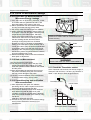
5-9 Microwave Heat Distribution - Heat Evenness
The microwave heat distribution can be checked indirectly by measuring the water temperature rise at
certain positions in the oven:
1. Prepare five beakers made of 'Pyrex', having 100 milliliters capacity each.
2. Measure exactly 100milliliters of water load with a measuring cylinder, and pour into each beaker.
3. Measure the temperature of each water load. (Readings shall be taken to the first place of decimals.)
4. Put each beaker in place on the plate tray as illustrated in figure below. Start heating.
5. After heating for 1 minute, measure the water temperature in each beaker.
6. Microwave heat distribution rate can be calculated as follows:
Heat Distribution =
Minimum
Temperature Rise
Maximum
Temperature Rise
D
X 100(%)
Beaker
D
D/4
The result should exceed 65%.
D/4
D/4
D/4
Samsung Electronics
Plate Tray
21
Alignment and Adjustments
5-10 Check for Microwave Leakage
5-10-1 Procedure for Measurement of
Microwave Energy Leakage
1) Pour 275 ±15cc of 20°C±5°C ( 68°F±9°F ) water
in a beaker which is graduated to 600cc, and
place the beaker in the center of the oven.
2) Start to operate the oven and measure the leakage
by using a microwave energy survey meter.
3) Set survey meter with dual ranges to 2,450MHz.
4) When measuring the leakage, always use the 2
inch spacer cone with the probe. Hold the probe
perpendicular to the cabinet door. Place the
spacer cone of the probe on the door and/or
cabinet door seam and move along the seam,
the door viewing window and the exhaust
openings moving the probe in a clockwise
direction at a rate of 1 inch/sec. If the leakage
testing of the cabinet door seam is taken near a
corner of the door, keep the probe perpendicular
to the areas making sure that the probe end at
the base of the cone does not get closer than 2
inches to any metal. If it gets closer than 2 inches,
erroneous readings may result.
5) Measured leakage must be less than 4mW/cm2,
after repair or adjustment.
Maximum leakage allowed is 5mW/cm2.
4mW/cm2 is used to allow for measurement and
meter accuracy
Probe
Spacer Cone
5-10-2 Note on Measurement
1) Do not exceed the limited scale.
2) The test probe must be held on the grip of the
handle, otherwise a false reading may result
when the operator's hand is between the handle
and the probe.
3) When high leakage is suspected, do not move
the probe horizontally along the oven surface;
this may cause damage to the probe.
4) Follow the recommendation of the manufacturer
of the microwave energy survey meter.
5-10-3 Record keeping and notification
after measurement
1) After adjustment and repair of a radiation
preventing device, make a repair record for the
measured values, and keep the data.
2) If the radiation leakage is more than 4mW/cm2
after determining that all parts are in good
condition, functioning properly and the identical
parts are replaced as listed in this manual, notify
that fact to ;
CENTRAL SERVICE CENTER
3) At least once a year have the microwave energy
survey meter checked for accuracy by its
manufacturer.
WARNING
AVOID THE HIGH VOLTAGE COMPONENTS.
5-11 Check the Thermistor sensor
If the Thermistor sensor does not fall into range of
maximum and minimum, it is fault. (eg. Resistor is
235KΩ ±12% at 25°C. Refer to figure below.)
Thermistor sensor
Circuit Tester
KΩ
Thermistor Sensor Temperature
22
Samsung Electronics
6. Troubleshooting
PRECAUTION
1. CHECK GROUNDING BEFORE CHECKING FOR TROUBLE.
2. BE CAREFUL OF THE HIGH VOLTAGE CIRCUIT.
3. DISCHARGE THE HIGH VOLTAGE CAPACITOR.
4. WHEN CHECKING THE CONTINUITY OF THE SWITCHES OR TRANSFORMER, DISCONNECT
LEAD WIRES FROM THESE PARTS AND THEN CHECK CONTINUITY WITHOUT THE POWER
SOURCE ON. TO DO OTHERWISE MAY RESULT IN A FALSE READING OR DAMAGE TO YOUR
METER.
5. DO NOT TOUCH ANY PART OF THE CIRCUIT OR THE CONTROL CIRCUIT BOARD, SINCE STATIC
DISCHARGE MAY DAMAGE IT. ALWAYS TOUCH GROUND WHILE WORKING ON IT TO
DISCHARGE ANY STATIC CHARGE BUILT UP.
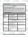
6-1 Electrical Malfunction
SYMPTOM
CAUSE
CORRECTIONS
Oven is dead.
Fuse is OK.
No display and no
operation.
1. Open or loose lead wire harness
2. Open thermal cutout (magnetron, cavity)
3. Open low voltage transformer
4. Defective Ass'y PCB
Check magnetron or cavity thermal cutout
switch is defective.
Check Ass'y PCB when LVT is defective.
No display and no
operation
Fuse blown out.
(10A, 1.6A)
1. Shorted lead wire
2. Defective primary latch switch (NOTE1)
3. Defective monitor switch (NOTE1)
4. Shorted HVCapacitor
5. Shorted HVTransformer (NOTE2)
Check adjustment of primary, interlock
monitor, door sensing switch.
NOTE 1: All of these switches must be replaced at the same time.
(refer to adjustment instructions)
Check continuity of main or power relay contacts and if it has continuity,
replace main or power relay also.
NOTE 2: When HVTransformer is replaced, check diode and magnetron also.
Oven does not accept
key input (Program)
(CM1229)
1. Key input is not in-Sequence
2. Open or loose connection of membrane
key pad to Ass'y PCB
3. Shorted or open membrane panel
4. Defective Ass'y PCB
1. Open or loose connection of high voltage
circuit especially magnetron filament
circuit
NOTE: Large contact resistance will bring
lower magnetron filament voltage and
Timer starts countdown
cause magnetron to lower output and/or
but no microwave
intermittent oscillation.
oscillation.
2. Defective high voltage components
(No heat while oven lamp
H.V.Transformer
and fan motor turn on.)
H.V.Capacitor
H.V.Diode, H.V.Fuse
Magnetron
Samsung Electronics
Refer to operation procedure.
Replace PCB main.
Adjust door and latch switches.
Check high voltage component
according to component test procedure
and replace if defective.
23
Troubleshooting
6-1 Electrical Malfunction(continued)
SYMPTOM
CAUSE
CORRECTIONS
Oven lamp goes off
1. Loose lead wire or open lamp
filament
2. Misadjustment of latch switch
3. Defective latch switch
Tighten lamp lead wire or replace with
a new lamp
Microwave output is low;.
Oven takes longer time
to cook food.
(No heat while oven lamp
and ventilation motor.)
1. Decrease in power source voltage.
2. Open or loose wiring of magnetron
filament circuit. (Intermittent oscillation)
3. Aging of magnetron
4. Defective high voltage components
H.V.Transformer
H.V.Capacitor
H.V.Diode,H.V.Fuse
Magnetron
Consult electrician.
Oven does not operate and
return to plugged-in mode.
Defective Ass'y PCB
Replace Ass’y PCB.
Loud buzzing noise can
be heard.
1. Loose fan and ventilation motor
2. Loose screws on H.V.Transformer
3. Shorted H.V.Diode
4. Loose or missing screws on
Cover-Back
Tighten screws of ventilation motor.
Tighten screws of H.V.Transformer.
Replace H.V.Diode.
Tighten screws of Cover-Back
Drive motor not
work. (Assy stirrer
does not rotate.)
1. Open or loose wiring of drive motor.
2. Defective drive motor.
3. Defective ass’y stirrer
Check the wire of drive motor
Replace drive motor.
Replace ass’y stirrer.
Oven stops operating
during cooking.
1. Operation of thermal cutout
(Magnetron or Cavity)
2. Ventilation motor does not rotate.
Adjust door and latch switches.
1. Metallic ware or cooking dishes
touching on the oven wall.
2. Ceramic ware trimmed with gold or
silver powder also causes sparks.
Inform the customer of proper use.
Uneven cooking
Uneven intensity of microwave due to
its characteristics.
Wrap thinner parts of the food with
aluminum foil.
Use plastic wrap or cover with a lid.
Stir once or twice while cooking
foods such as soup, cocoa, or milk.
Noise from turntable motor
when it starts to operate.
Noise may result from the motor.
Replace turntable motor.
Oven can program but
timer does not start.
Defective circuitry of Start function
of Main PCB Ass’y.
Check circuitry of Start function
of Main PCB Ass’y and replace if
defective.
Adjust or repair loose wires.
Sparks
Loose lead wires
24
Check high voltage component
according to component test procedure
and replace if defective.
Replace ventilation motor.
Do not use any type of cookware
with metallic trimming.
Samsung Electronics
Troubleshooting
6-2 Error Codes & Corrections
Code
Cause
Corrections
E1
1. Improper input power frequency
2. Defective Ass’y Main PCB
Check if power frequency is 50Hz.
Replace Ass’y Main PCB or MICOM.
E21
1. Thermistor sensor failure
2. Thermistor sensor open
3. Loose connector CN2
Check resistance of thermistor sensor
and replace if defective.
Check the circuitry around thermistor sensor.
E22
1. Thermistor sensor failure
Check resistance of Thermistor sensor
and replace if defective.
If Thermistor sensor is short, replace.
Check the circuitry around Thermistor sensor.
2. Thermistor sensor short
3. Thermistor sensor wire short
E3
1. Overheating inside cavity
(no load or little load aging)
2. Air ventilation blocked around
exhaust area
3. Ventilation motor failure and
magnetron overheating
E41
1. Main Relay (RY1) or
Power Relay (RY2) failure
2. Loose lead wires of relay
3. Primary or Monitor S/W failure
4. Loose lead wires of Primary
or Monitor S/W
5. H.V.Trans input power sensing
circuitry failure
E42
E5
CM1229
Check if the oven was operating
without load or too little load
and plug the power cord in again.
If error code ‘E3’ appears again in the
window display, check resistance of
Thermistor sensor and replace if defective.
Check if any blocking amterials exist
around the Air Exhaust or ventilation
openings and follow the instructions above.
Check if the ventilation motor is operative
and replace the motor if defective.
Check Main Relay (RY1), Power Relay (RY2)
Primary S/W and Monitor S/W and replace
if defective.
Check if lead wires are loosened and connect
firmly if loose.
Check the circuitry and replace if defective.
(Refer to Operating Sequence as shown in page 42.)
1. Power Relay (RY5) failure
2. Loose lead wires of
Power Relay (RY5)
3. Primary or Monitor S/W failure
4. Loose lead wires of
Primary or Monitor S/W
5. Fuse(10A) blown out on neutral
area of Ass’y Noise Filter
6. H.V.Trans input power sensing
circuit failure
Check Power Relay2, Primary S/W, Monitor S/W
or Fuse and replace if defective.
Check if lead wires are loosened and repair as
necessary.
1. Memory IC (EEPROM IC) failure
Check Memory IC (IC3) and replace if defective.
2. MICOM failure
Replace Assy Main PCB or MICOM.
Samsung Electronics
Check the circuitry. (Refer to Operating Sequence
as shown in page 42.)
25
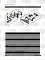
7. Exploded Views and Parts List
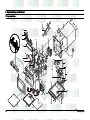
7-1 Exploded Views
MM03
MM01
MM49
MM36
MM59
MM11
MM06
MM10
MM85
MM44
MM43
MM171
(CM1229)
MM38
MM41
MM72
MM17
MM40
MM07
MM88(1229)
MM22
MM30
MM35
MM05
MM29
MM31
(CM1219)
MM14
MM55
MM87
MM39
MM48
MM551
MM32
MB05
MB03
MB041
MB02
MM37
MB01
MM28
MM33
MM46
MB03
MB07
MB042
MM08
MM47
MM18
MM86
MM16
26
Samsung Electronics
Exploded Views and Parts List
7-2 Main Parts List(CM1219)
No.
MB01
MB02
MB03
MB041
MB042
MB05
MB07
MM01
MM03
MM05
MM06
MM07
MM08
MM10
MM11
MM14
MM16
MM17
MM171
MM18
MM22
MM28
Part Code
Description
DE93-20097C ASSY BODY LATCH
3405-000175
SWITCH-MICRO
3405-000178
SWITCH-MICRO
DE66-90107A LEVER-SWITCH/U
DE66-90108A LEVER-SWITCH/L
DE66-40062A LATCH-BODY
DE61-00066A SPRING-Q
DE70-30123A PANEL-OUTER
DE39-00025A WIRE HARNESS-A
DE91-40105A ASSY NOISE FILTER
DE91-50093G ASSY MOTOR-FAN
DE39-20143B ASSY POWER CORD
OM75P(20)ESS ASSY-MAGNETRON
4713-000168
LAMP-INCANDESCENT
DE47-40029A SOCKET-LAMP
DE26-10150A TRANS-H.V
DE71-60424A COVER-CEILING
DE47-20017A THERMOSTAT
DE47-20197A THERMOSTAT
DE92-90488A ASSY-TRAY CERAMIC
DE31-10164B MOTOR-SYNCHRONOUS
DE80-10113C BASE-PLATE
MM29 2501-001114
MM30
MM31
MM32
MM33
MM35
MM36
MM37
MM38
MM39
MM40
MM41
MM43
MM44
MM46
MM47
MM48
MM49
MM55
MM551
MM59
MM72
MM85
MM86
MM87
DE61-50120A
DE91-70063A
DE91-70061C
DE26-20162A
DE32-10013A
DE61-90318A
DE69-90054A
DE72-50088A
DE72-50089A
DE72-50090A
2301-001204
DE61-30189A
DE61-50520A
DE92-90515A
DE92-90516B
DE61-50568A
DE71-60422A
3601-000448
3601-001126
DE71-60421A
DE61-50541A
DE72-50091A
DE71-60423A
DE93-90112A
Samsung Electronics
Specification
CM1819/1829,EUROPE,-,-,-,250V,15A,200gf,SPST-NO
250V,15A,200gf,SPST-NO
PBT,CM-1819,-,-,-,-,PBT,CM-1819,-,-,-,-,PP,CM-1819,-,-,-,MSWR,PI0.8,-,-,-,-,CM1819/1829,STS430,T0.6,CM-1819,-,-,-,-,-,
-,-,-,-,CM1819
SN-1829,230V/50Hz,-,-,-,-,-,240V,2250RPM,CM1219/1229,-,U13A1,-,250V,13A,L2200,BLK,-,OM75P(20)ESS
230V,-,25W,ORG,-,-,250V2A,22.23,E14,BJB,-,-,SHV-906BG1,240V,2360V/3.35V,50
MICA_SHEET,T0.5,W348,L319,CM-1
PW-2N(150/60,187Z),250V/7.5A,1
NT-101NA(8XV)P,100/60,250V/7.5
CM-1819,-,-,-,-,M2CK34A709-H(B),120V60HZ,34.9r
SECC1,-,-,-,CM1819,-
C-OIL
740nF,201KV,BK,54X35X65mm,20mm
BRACKET-HVC
ASSY-HVD
ASSY-H.V.FUSE
TRANS-L.V
SENSOR-THERMISTOR
HOLDER-LAMP
CLIP-STIRRER
DUCT-FAN
DUCT-MGT/R
DUCT-MGT/L
C-FILM,PEF
SUPPORTER-FAN-MOUNT
BRACKET-PCB
ASSY-STIRRER
ASSY-BRACKET FILTER
BRACKET-SUPPORT
COVER-LAMP
FUSE-CARTRIDGE
FUSE-CARTRIDGE
COVER-BACK
BRACKET-EARTH
DUCT-OVEN
COVER-STIRRER
ASSY-B/RESISTOR
SECC,T0.6,W62,L72,-,-,V2M6,P19.0,0.05MT,-,-,-,-,-
Q'ty Remark
1
2
3
1
1
1
1
1
1
1
1
1
2
2
2
2
2
1
1
1
2
1
2
-
2
2
2
THV060T-0700-H,5KV/0.70A,BLU
SLV-1829E,230,19.7/3.1V,50Hz,4
1
PT-312-K2,-,-,-,-,-,1
SECC,T0.8,W134,L40.5,-,-,-,-,1
PFA,5mm,CM1819/29,-,-,6
ALCOAT,T0.5,CM-1819,-,-,-,-,-,
1
SECC,T0.5,CM-1819,-,-,-,-,-,1
SECC,T0.5,-,-,-,CM-1819,1
1.50uF,-5to+10%,450VAC,-,48x17
1
SECC,T1.0,CM-1819,-,-,-,1
SECC,T0.8,CM-1819,-,-,-,1
CM-1819,CM-1829,-,-,-,2
CM1819,-,-,-,-,1
SECC/ALCOAT,T0.6,W100,L100,-,C
1
STS430,T0.6,CM-1819,-,-,-,-,-,
1
250V,10A,SLOW-BLOW,CERAMIC,6.35x31.8mm
2
1
250V,1.6A,FAST-ACTING,CERAMIC,5x20mm
SECC,T0.6,W481.8,L363.9,CM-181
1
SGCC2,T1.0,W15,L8,-,-,1
STS430,T0.4,CM-1819,-,-,-,-,-,
1
PP,CM-1819,-,-,-,-,-,-,1
CM1819/29,-,-,-,-,2
-
27
Exploded Views and Parts List
7-3 Main Parts List(CM1229)
No.
MB01
MB02
MB03
MB041
MB042
MB05
MB07
MM01
MM03
MM05
MM06
MM07
MM08
MM10
MM11
MM14
MM16
MM17
MM171
MM18
MM22
MM28
MM29
MM30
MM31
MM32
MM33
MM35
MM36
MM37
MM38
MM39
MM40
MM41
MM43
MM44
MM46
MM47
MM48
MM49
MM51
MM53
MM55
MM551
MM59
MM72
MM85
MM86
MM87
MM88
Part Code
DE93-20097C
3405-000175
3405-000178
DE66-90107A
DE66-90108A
DE66-40062A
DE61-00066A
DE70-30123A
DE39-00025A
DE91-40105A
DE91-50093G
DE39-20143B
OM75P(20)ESS
4713-000168
DE47-40029A
DE26-10150A
DE71-60424A
DE47-20017A
DE47-20197A
DE92-90488A
DE31-10164B
DE80-10113C
2501-001114
DE61-50120A
DE59-70063A
DE91-70061C
DE26-20162A
DE32-10013A
DE61-90318A
DE69-90054A
DE72-50088A
DE72-50089A
DE72-50090A
2301-001204
DE61-30189A
DE61-50520A
DE92-90515A
DE92-90516B
DE61-50568A
DE71-60422A
DE63-90190B
DE01-00095A
3601-000448
3601-001126
DE71-60421A
DE61-50541A
DE72-50091A
DE71-60423A
DE93-90112A
DE73-90027A
Samsung Electronics
Description
Specification
Q'ty
Remark
ASSY BODY LATCH
CM1819/1829,EUROPE,-,-,-,1
SWITCH-MICRO
250V,15A,200gf,SPST-NO
2
SWITCH-MICRO
250V,15A,200gf,SPST-NO
3
LEVER-SWITCH/U
PBT,CM-1819,-,-,-,-,1
LEVER-SWITCH/L
PBT,CM-1819,-,-,-,-,1
LATCH-BODY
PP,CM-1819,-,-,-,1
SPRING-Q
MSWR,PI0.8,-,-,-,-,CM1819/1829,1
PANEL-OUTER
STS430,T0.6,CM-1819,-,-,-,-,-,
1
WIRE HARNESS-A
-,-,-,-,CM1819
1
ASSY NOISE FILTER
SN-1829,230V/50Hz,-,-,-,-,1
ASSY MOTOR-FAN
-,240V,2250RPM,CM1219/1229,-,-,-,-,1
ASSY POWER CORD
U13A1,-,250V,13A,L2200,BLK,-,1
ASSY-MAGNETRON
OM75P(20)ESS
2
LAMP-INCANDESCENT
230V,-,25W,ORG,-,-,2
SOCKET-LAMP
250V2A,22.23,E14,BJB,-,-,2
TRANS-H.V
SHV-906BG1,240V,2360V/3.35V,50
2
COVER-CEILING
MICA_SHEET,T0.5,W348,L319,CM-1
2
THERMOSTAT
PW-2N(150/60,187Z),250V/7.5A,1
1
THERMOSTAT
NT-101NA(8XV)P,100/60,250V/7.5
1
ASSY-TRAY CERAMIC
CM-1819,-,-,-,-,1
MOTOR-SYNCHRONOUS M2CK34A709-H(B),120V60HZ,34.9r
2
BASE-PLATE
SECC1,-,-,-,CM1819,1
C-OIL
740nF,2.1KV,BK,54x35x65,20mm
2
BRACKET-HVC
SECC,T0.6,W62,L72,-,-,2
ASSY-HVD
V2M6,P19.0,0.05MT,-,-,-,-,2
ASSY-H.V.FUSE
THV060T-0700-H,5KV/0.70A,BLE
2
TRANS-L.V
SLV-1829E,230,19.7/3.1V,50Hz,4
1
SENSOR-THERMISTOR PT-312-K2,-,-,-,-,-,1
HOLDER-LAMP
SECC,T0.8,W134,L40.5,-,-,-,-,1
CLIP-STIRRER
PFA,5mm,CM1819/29,-,-,6
DUCT-FAN
ALCOAT,T0.5,CM-1819,-,-,-,-,-,
1
DUCT-MGT/R
SECC,T0.5,CM-1819,-,-,-,-,-,1
DUCT-MGT/L
SECC,T0.5,-,-,-,CM-1819,1
C-FILM,PEF
1.50uF,-5to+10%,450VAC,-,48x17
1
SUPPORTER-FAN-MOUNTSECC,T1.0,CM-1819,-,-,-,1
BRACKET-PCB
SECC,T0.8,CM-1819,-,-,-,1
ASSY-STIRRER
CM-1819,CM-1829,-,-,-,2
ASSY-BRACKET FILTER CM1819,-,-,-,-,1
BRACKET-SUPPORT
SECC/ALCOAT,T0.6,W100,L100,-,C
1
COVER-LAMP
STS430,T0.6,CM-1819,-,-,-,-,-,
1
CUSHION-LAMP
-,T7.0,W100,L120,-,CM1819/29,PUT-FOAM
1
FILM-LAMP
PET,T0.15,114,84,CM-1819,-,-,1
FUSE-CARTRIDGE
250V,10A,SLOW-BLOW,CERAMIC,6.35x31.8mm 2
FUSE-CARTRIDGE
250V,1.6A,FAST-ACTING,CERAMIC,5x20mm
1
COVER-BACK
SECC,T0.6,W481.8,L363.9,CM-181
1
BRACKET-EARTH
SGCC2,T1.0,W15,L8,-,-,1
DUCT-OVEN
STS430,T0.4,CM-1819,-,-,-,-,-,
1
COVER-STIRRER
PP,CM-1819,-,-,-,-,-,-,1
ASSY-B/RESISTOR
CM1819/29,-,-,-,-,2
FERRITE-CORE
NI-ZN,T13.8,W21.0,L28.0,BNF-14
2 H.V.T
28
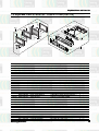
Exploded Views and Parts List
7-3 Exploded View & Parts List - Control & Door(CM1219)
MD06
MD08
MD04
MC22
MC20
MD15
MD01
MD17
MC21
MD10
MD16
MC16
MC06
MD07
MC18
MD13
MC09
MC11
MC14
MC17
MC07
MD18
MC15
MD14
MC19
No.
MC01
MC06
MC07
MC09
MC11
MC13
MC14
MC15
MC16
MC17
MC18
MC19
MC20
MC21
MC22
MD01
MD04
MD06
MD07
MD08
MD10
MD13
MD14
MD15
MD16
MD17
MD18
Part Code
Description
Specification
DE93-30443E ASSY CONTROL-BOX
-,CM1219-,EUROPE,-,-,-,-,DE67-40161A WINDOW-DISPLAY
RESIN-PMMA,82555,CM-1819,-,-,CM-121;
RC-CM1819-10 ASSY PCB PARTS
DE64-10143A KNOB-POWER
RESIN-ABS,CM-1819,Ni,Cr-platin
DE64-10144A KNOB-TIMER
RESIN-ABS,CM-1819,Ni,Cr-platin
DE93-30528A ASSY CONTROL-PANEL CM1419/1819,-,-,-,-,-,DE66-20211A BUTTON-SELECT
RESIN-ABS,CM-1829,Ni,Cr-platin
DE66-20212A BUTTON-START
RESIN-ABS,CM-1819,Ni,Cr-platin
DE70-30126A PANEL-BASE
RESIN-ABS,ME,CM-1819,-,-,-,-,DE71-60427A COVER-PANEL
STS430,T0.5,ME,CM-1829,-,-,-,DE71-60428B COVER-PANEL/L
ABS,-,-,-,NICR COATING,CM1019
DE71-60429B COVER-PANEL/R
ABS,-,-,-,NICR COATING,CM1019
DE39-40694A WIRE HARNESS-C
230V50Hz,CM-1819/29,EUROPE,-,DE39-40695A WIRE HARNESS-D
230V50Hz,CM-1819,EUROPE,-,-,DE39-40692A WIRE HARNESS-B
230V50HZ,CM1819/29,EUROPE,-,-,
DE92-40241L ASSY DOOR
CM1219,-,STS430,1200W
DE92-50132B ASSY DOOR-E
CM-1819,COATING,BLK,-,-,-,DE64-40298A DOOR-C
PP,CM-1819,-,-,-,-,DE61-70144A SPRING-KEY
PI6.5,D0.8,-,-,-,CM-1819,DE61-80138A HINGE
SCP1,T3.0,W24.5,L29.5,-,-,-,-,
DE64-40296A DOOR-KEY
CR3C,-,-,-,-,-,DE60-60080A PIN-KEY
A,M3.95,L21,STS304,-,CM-1819,DE64-20123A HANDLE
ZN-DICASTING,500G,CM-1819,-,CM
DE64-90145A DECORATION-DOOR
ABS,CM-1819,-,-,-,-,-,-,DE64-90146A DECORATION-COV/DOOR STS,CM-1819,-,-,-,-,-,-,DE67-20174A SCREEN-DOOR(B)
TEMP-GLASS,T3.2,-,-,-,-,-,-,DE71-60433A COVER-HANDLE
STS430,T0.5,CM-1819,-,-,-,-,-,
Samsung Electronics
MC01
Q'ty
Remark
1
1
1
1
1
1
1
1
1
1
1
1
1
1
1
1
1
1
2
2
2
2
1
1
1
1
1
DOOR-E
-
29
Exploded Views and Parts List
7-3 Exploded View & Parts List - Control & Door(CM1229)
MD06
MD08
MD04
MD01
MD15
MC20
MC07
MC01
MD17
MD16
MC16
MD10
MC22
MC27
MC06
MD07
MD13
MC18
MC17
MC15
MD18
MC02
MD14
MC19
No.
MC01
MC02
MC06
MC07
MC13
MC15
MC16
MC17
MC18
MC19
MC20
MC22
MC27
MD01
MD04
MD06
MD07
MD08
MD10
MD13
MD14
MD15
MD16
MD17
MD18
30
Part Code
DE93-30442B
DE34-00034A
DE67-40161A
RC-CM1819-11
DE93-30529C
DE66-20212A
DE70-30125A
DE71-60426A
DE71-60428B
DE71-60429B
DE39-40694A
DE39-40692A
DE39-40113B
DE92-40214M
DE92-50132B
DE64-40298A
DE61-70144A
DE61-80138A
DE64-40296A
DE60-60080A
DE64-20123A
DE64-90145A
DE64-90146A
DE67-20174A
DE71-60433A
Description
Specification
ASSY CONTROL-BOX
-,CM1229,-,EUROPE,-,-,-,-,-,SWITCH-MEMBRANE
PET,CM1229/XEU,230V50Hz,-,-,WINDOW-DISPLAY
RESIN-PMMA,82555,CM-1819,-,-,ASSY PCB PARTS
CM-122;
ASSY CONTROL-PANEL CM1229,-,EUROPE,-,-,-,-,-,BUTTON-START
RESIN-ABS,CM-1819,Ni,Cr-platin
PANEL-BASE
RESIN-ABS,TC,CM-1829,-,-,-,-,COVER-PANEL
STS430,T0.5,TC,CM-1829,-,-,-,COVER-PANEL/L
ABS,-,-,-,NICR COATING,CM1019
COVER-PANEL/R
ABS,-,-,-,NICR COATING,CM1019
WIRE HARNESS-C
230V50Hz,CM-1819/29,EUROPE,-,WIRE HARNESS-B
230V50HZ,CM1819/29,EUROPE,-,-,
WIRE HARNESS-F
100V,50/60HZ,RE-CH1,-,-,ASSY DOOR
CM1229,-,STS430,1200W-,-,ASSY DOOR-E
CM-1819,COATING,BLK,-,-,-,DOOR-C
PP,CM-1819,-,-,-,-,SPRING-KEY
PI6.5,D0.8,-,-,-,CM-1819,HINGE
SCP1,T3.0,W24.5,L29.5,-,-,-,-,
DOOR-KEY
CR3C,-,-,-,-,-,PIN-KEY
A,M3.95,L21,STS304,-,CM-1819,HANDLE
ZN-DICASTING,500G,CM-1819,-,CM
DECORATION-DOOR
ABS,CM-1819,-,-,-,-,-,-,DECORATION-COV/DOOR STS,CM-1819,-,-,-,-,-,-,SCREEN-DOOR(B)
TEMP-GLASS,T3.2,-,-,-,-,-,-,COVER-HANDLE
STS430,T0.5,CM-1819,-,-,-,-,-,
Q'ty
1
1
1
1
1
1
1
1
1
1
1
1
1
1
1
1
2
2
2
2
1
1
1
1
1
Remark
DOOR-E
-
Samsung Electronics
Exploded Views and Parts List
7-6 Parts List - Standard Parts(CM1219)
Part Code
6011-001140
DE60-10012A
DE60-10012A
DE60-10012A
DE60-10012A
DE60-10080B
DE60-10082H
DE60-10082H
DE60-10088A
DE60-10098A
DE60-10098A
DE60-10098A
DE60-10098A
DE60-10098A
DE60-10098A
DE60-10196A
DE60-10196A
DE60-10196A
DE60-10199A
DE60-10199A
DE60-10199A
DE60-10199A
DE60-10199A
DE60-10199A
DE60-10199A
DE60-10199A
DE60-10199A
DE60-10199A
DE60-20014A
DE60-30015A
DE60-10082H
DE60-10098A
DE60-10098A
DE60-10121A
DE60-10022A
DE60-10088A
Description
BOLT-STUD
SCREW-TAP TITE
SCREW-TAP TITE
SCREW-TAP TITE
SCREW-TAP TITE
SCREW-WASHER
SCREW-A
SCREW-A
SCREW-TAP PH
SCREW-ASSY TAP TITE
SCREW-ASSY TAP TITE
SCREW-ASSY TAP TITE
SCREW-ASSY TAP TITE
SCREW-ASSY TAP TITE
SCREW-ASSY TAP TITE
SCREW-TAP OH
SCREW-TAP OH
SCREW-TAP OH
SCREW-WASHER
SCREW-WASHER
SCREW-WASHER
SCREW-WASHER
SCREW-WASHER
SCREW-WASHER
SCREW-WASHER
SCREW-WASHER
SCREW-WASHER
SCREW-WASHER
BOLT-FLANGE
NUT-FLANGE
SCREW-A
SCREW-ASSY TAP TITE
SCREW-ASSY TAP TITE
SCREW-TAP TH
SCREW-PH
SCREW-TAP PH
Samsung Electronics
Specification
M4,L8,Ni PLT,BSW
TH,+,3,M4,L10,SWR10,ZPC2,TOOTH
TH,+,3,M4,L10,SWR10,ZPC2,TOOTH
TH,+,3,M4,L10,SWR10,ZPC2,TOOTH
TH,+,3,M4,L10,SWR10,ZPC2,TOOTH
PH,PI5,L10,SWRCH18A,ZP2,2S,-,2S-4X12,TOOTHED,-,-,-,-,-,-,-,
2S-4X12,TOOTHED,-,-,-,-,-,-,-,
PH,M3,L8,FEFZY,PLAIN,-,-,-,-,PH,TC,M4X8,SWRCH18A,ZPC2,GLD,W
PH,TC,M4X8,SWRCH18A,ZPC2,GLD,W
PH,TC,M4X8,SWRCH18A,ZPC2,GLD,W
PH,TC,M4X8,SWRCH18A,ZPC2,GLD,W
PH,TC,M4X8,SWRCH18A,ZPC2,GLD,W
PH,TC,M4X8,SWRCH18A,ZPC2,GLD,W
OH+FH,+,-,4,L8,MSWR18C,Ni,SIL,
OH+FH,+,-,4,L8,MSWR18C,Ni,SIL,
OH+FH,+,-,4,L8,MSWR18C,Ni,SIL,
TH(WASHER),+,-,4,L10,MSWR18C,N
TH(WASHER),+,-,4,L10,MSWR18C,N
TH(WASHER),+,-,4,L10,MSWR18C,N
TH(WASHER),+,-,4,L10,MSWR18C,N
TH(WASHER),+,-,4,L10,MSWR18C,N
TH(WASHER),+,-,4,L10,MSWR18C,N
TH(WASHER),+,-,4,L10,MSWR18C,N
TH(WASHER),+,-,4,L10,MSWR18C,N
TH(WASHER),+,-,4,L10,MSWR18C,N
TH(WASHER),+,-,4,L10,MSWR18C,N
M5,L10,MSWR3,FEFZY,-,-,-,-,M5,P0.8,MSWR10,FEFZY,-,-,-,-,2S-4X12,TOOTHED,-,-,-,-,-,-,-,
PH,TC,M4X8,SWRCH18A,ZPC2,GLD,W
PH,TC,M4X8,SWRCH18A,ZPC2,GLD,W
2-4X8,FE,FZY,(77128-540-081,SA
PH,+,M3,L8,MSWR10,FEFZY,-,-,-,
PH,M3,L8,FEFZY,PLAIN,-,-,-,-,-
Remark
BACK-COVER
BKT-LAMP
LVT
P/CORD EARTH
HVT
BODY-LATCH
C-PANEL
MAIN PCB
BKT-HIN-L
BKT-HIN-U
BKT-MOTOR
DUCT-FAN
DUCT-MGT-L
DUCT-MGT-R
BASE
COVER-LAMP
OUTPANEL
BACK-COVER
BKT-PCB
C-RESISTOR
CAVI-BACK
DUCT-MGT-L
DUCT-MGT-R
DUCT-OVEN
OUTPANEL
SUP-FAN
THERMISTOR
MGT
HANDLE
DECORATION
TCO-DUCT
PCB
31
tExploded Views and Parts List
Exploded
7-7 Parts List - Standard Parts(CM1229)
Part Code
6011- 001140
DE60- 10012A
DE60- 10012A
DE60- 10012A
DE60- 10012A
DE60- 10080B
DE60- 10082H
DE60- 10082H
DE60- 10088A
DE60- 10098A
DE60- 10098A
DE60- 10098A
DE60- 10098A
DE60- 10098A
DE60- 10098A
DE60- 10098A
DE60- 10194A
DE60- 10196A
DE60- 10196A
DE60- 10196A
DE60- 10199A
DE60- 10199A
DE60- 10199A
DE60- 10199A
DE60- 10199A
DE60- 10199A
DE60- 10199A
DE60- 10199A
DE60- 10199A
DE60- 10199A
DE60- 20014A
DE60- 30015A
DE60- 10082H
DE60- 10098A
DE60- 10098A
DE60- 10121A
DE60- 10022A
DE60- 10088A
DE60- 10088A
32
Description
BOLT- STUD
SCREW- TAP TITE
SCREW- TAP TITE
SCREW- TAP TITE
SCREW- TAP TITE
SCREW- WASHER
SCREW- A
SCREW- A
SCREW- TAP PH
SCREW- ASSY TAP
SCREW- ASSY TAP
SCREW- ASSY TAP
SCREW- ASSY TAP
SCREW- ASSY TAP
SCREW- ASSY TAP
SCREW- ASSY TAP
SCREW- TAPPING
SCREW- TAP OH
SCREW- TAP OH
SCREW- TAP OH
SCREW- WASHER
SCREW- WASHER
SCREW- WASHER
SCREW- WASHER
SCREW- WASHER
SCREW- WASHER
SCREW- WASHER
SCREW- WASHER
SCREW- WASHER
SCREW- WASHER
BOLT- FLANGE
NUT- FLANGE
SCREW- A
SCREW- ASSY TAP
SCREW- ASSY TAP
SCREW- TAP TH
SCREW- PH
SCREW- TAP PH
SCREW- TAP PH
Specification
TITE
TITE
TITE
TITE
TITE
TITE
TITE
TITE
TITE
M4,L8,Ni PLT,BSW
TH,+,3,M4,L10,SWR10,ZPC2,TOOTH
TH,+,3,M4,L10,SWR10,ZPC2,TOOTH
TH,+,3,M4,L10,SWR10,ZPC2,TOOTH
TH,+,3,M4,L10,SWR10,ZPC2,TOOTH
PH,PI5,L10,SWRCH18A,ZP2,2S,- ,2S- 4X12,TOOTHED,- ,- ,- ,- ,- ,- ,- ,
2S- 4X12,TOOTHED,- ,- ,- ,- ,- ,- ,- ,
PH,M3,L8,FEFZY,PLAIN,- ,- ,- ,- ,PH,TC,M4X8,SWRCH18A,ZPC2,GLD,W
PH,TC,M4X8,SWRCH18A,ZPC2,GLD,W
PH,TC,M4X8,SWRCH18A,ZPC2,GLD,W
PH,TC,M4X8,SWRCH18A,ZPC2,GLD,W
PH,TC,M4X8,SWRCH18A,ZPC2,GLD,W
PH,TC,M4X8,SWRCH18A,ZPC2,GLD,W
PH,TC,M4X8,SWRCH18A,ZPC2,GLD,W
PH,+,2S,M3,L12,MSWR12,ZPC2,PLA
OH+FH,+,- ,4,L8,MSWR18C,Ni,SIL,
OH+FH,+,- ,4,L8,MSWR18C,Ni,SIL,
OH+FH,+,- ,4,L8,MSWR18C,Ni,SIL,
TH(WASHER),+,- ,4,L10,MSWR18C,N
TH(WASHER),+,- ,4,L10,MSWR18C,N
TH(WASHER),+,- ,4,L10,MSWR18C,N
TH(WASHER),+,- ,4,L10,MSWR18C,N
TH(WASHER),+,- ,4,L10,MSWR18C,N
TH(WASHER),+,- ,4,L10,MSWR18C,N
TH(WASHER),+,- ,4,L10,MSWR18C,N
TH(WASHER),+,- ,4,L10,MSWR18C,N
TH(WASHER),+,- ,4,L10,MSWR18C,N
TH(WASHER),+,- ,4,L10,MSWR18C,N
M5,L10,MSWR3,FEFZY,- ,- ,- ,- ,M5,P0.8,MSWR10,FEFZY,- ,- ,- ,- ,2S- 4X12,TOOTHED,- ,- ,- ,- ,- ,- ,- ,
PH,TC,M4X8,SWRCH18A,ZPC2,GLD,W
PH,TC,M4X8,SWRCH18A,ZPC2,GLD,W
2- 4X8,FE,FZY,(77128- 540- 081,SA
PH,+,M3,L8,MSWR10,FEFZY,- ,- ,- ,
PH,M3,L8,FEFZY,PLAIN,- ,- ,- ,- ,PH,M3,L8,FEFZY,PLAIN,- ,- ,- ,- ,-
Q'ty
2
1
1
1
1
8
2
3
4
1
1
2
2
1
1
1
2
3
1
4
8
2
2
4
1
1
2
7
2
1
4
8
5
4
2
3
1
2
2
Remark
BACK- COVER
BKT- LAMP
LVT
P/ C EARTH
HVT
BODY- LATCH
C- PANEL
MAIN PCB
BKT- HIN- L
BKT- HIN- U
BKT- MOTOR
DUCT- FAN
DUCT- MGT- L
DUCT- MGT- R
MEM EARTH
BASE
COVER- LAMP
OUTPANEL
BACK- COVER
BKT- PCB
C- RESISTOR
CAVI- BACK
DUCT- MGT- L
DUCT- MGT- R
DUCT- OVEN
OUTPANEL
SUP- FAN
THERMISTOR
MGT
HANDLE
DECORATION
TCO- DUCT
PCB
Samsung Electronics
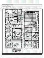
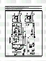
8. P.C.B Circuit Diagrams and Parts List
8-1 P.C.B Circuit Diagram (CM1219)
Samsung Electronics
33
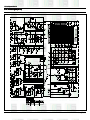
P.C.B Circuit Diagrams and Parts List
8-2 P.C.B Circuit Diagram (CM1229)
34
Samsung Electronics
P.C.B Diagrams and Parts List
8-3 P.C.B Parts List (CM1219)
Part Code
0604-000237
3002-000198
3406-001031
3406-001032
3501-001015
3501-001016
3711-000315
3711-000570
3711-000577
3711-000616
3711-001154
DE07-10088A
DE09-00117A
DE13-20016A
DE61-90178A
0401-001025
0402-000137
0402-001103
0403-000525
0403-000537
0501-000389
0504-001045
2001-000003
2001-000290
2001-000405
2001-000429
2001-000435
2001-000577
2001-000613
2001-000780
2001-000786
2001-001077
2003-000236
2003-000462
2004-000195
2004-000729
2011-000582
2202-000121
2202-000205
2202-000780
2401-000037
2401-000180
2401-000466
2401-000598
2401-000914
2401-001415
2401-002075
2801-003214
3404-001022
3711-000203
3711-000940
3711-000999
DE13-20009A
DE39-60001A
Description
PHOTO-COUPLER
BUZZER-PIEZO
SWITCH-ROTARY
SWITCH-ROTARY
RELAY-POWER
RELAY-MINIATURE
CONNECTOR-HEADER
CONNECTOR-HEADER
CONNECTOR-HEADER
CONNECTOR-HEADER
CONNECTOR-HEADER
V.F.DISPLAY
IC-MCU
IC-VOLT REGU
HOLDER-DIGITRON
DIODE-SWITCHING
DIODE-RECTIFIER
DIODE-RECTIFIER
DIODE-ZENER
DIODE-ZENER
TR-SMALL SIGNAL
TR-DIGITAL
R-CARBON
R-CARBON
R-CARBON
R-CARBON
R-CARBON
R-CARBON
R-CARBON
R-CARBON
R-CARBON
R-CARBON(S)
R-METAL OXIDE
R-METAL OXIDE(S)
R-METAL
R-METAL
R-NETWORK
C-CERAMIC,MLC-AXIAL
C-CERAMIC,MLC-AXIAL
C-CERAMIC,MLC-AXIAL
C-AL
C-AL
C-AL
C-AL
C-AL
C-AL
C-AL
CRYSTAL-UNIT
SWITCH-TACT
CONNECTOR-HEADER
CONNECTOR-HEADER
CONNECTOR-HEADER
IC
WIRE-SO COPPER
Samsung Electronics
Specification
Q'ty
TR,50-600%,200mW,DIP-4,ST
2
80dB,-,-,4KHz,ST
1
10V,1mA,DP24T,18.3mm
1
28VDC,10mA,DP6T,20mm
1
24V,21.8mA,16A,1FormA,20mS,10m
3
24V,12.5mA,5A,1FormA,8mS,4mS
4
1WALL,7P,1R,3.96mm,STRAIGHT,SN
2
BOX,10P,1R,2.50mm,ANGLE,SN
1
BOX,10P,1R,2.5mm,STRAIGHT,SN
1
BOX,11P,1R,2.5mm,STRAIGHT,SN
2
BOX,9P,1R,2.5mm,STRAIGHT,SN
2
SVM-06MM29,REDDISHORG/GRN,6G,5 1
HD4074339SI-,-,32K SDIP-64PIN,1
KA7805A,TO-220AB,1A,0/125C,-,1
NY66,CM-1819,-,-,-,-,-,-,1
1N4148M,50V,450mA,DO-34,TP
7
1N4007,1000V,1A,DO-41,TP
2
1T4,400V,1A,TS-1,TP
12
1N4733A,5.1V,5%,1W,DO-41,TP
1
1N4749A,24V,5%,1W,DO-41,TP
2
KSC815,NPN,400mW,TO-92,TP,1201
KRC119M,NPN,400MW,4.7K/10K,TO-92M,TP
12
330ohm,5%,1/8W,AA,TP,1.8x3.2mm
2
10KOHM,5%,1/8W,AA,TP,1.8X3.2MM
14
180OHM,5%,1/8W,AA,TP,1.8X3.2MM
1
1KOHM,5%,1/8W,AA,TP,1.8X3.2MM
9
1MOHM,5%,1/8W,AA,TP,1.8X3.2MM
1
2KOHM,5%,1/8W,AA,TP,1.8X3.2MM
2
3.9KOHM,5%,1/8W,AA,TP,1.8X3.2MM
2
470OHM,5%,1/8W,AA,TP,1.8X3.2MM
3
47KOHM,5%,1/8W,AA,TP,1.8X3.2MM
2
150OHM,5%,1/2W,AA,TP,2.4X6.4MM
2
270ohm,5%,2W,AA,TP,6x16mm
1
10Kohm,5%,2W,AA,TP,4x12mm
8
100Kohm,1%,1/8W,AA,TP,1.8x3.2m
1
3.9Kohm,1%,1/8W,AA,TP,1.8x3.2m
1
47Kohm,5%,1/8W,A,SIP,9P,BK
2
100pF,10%,50V,Y5P,TP,1.9x3.5,5
22pF,5%,50V,SL,TP,1.9x3.5,2
100nF,+80-20%,50V,Y5V,TP,3.5x1
6
470uF,20%,16V,GP,TP,8x11.5,5
1
1000uF,20%,35V,GP,-,16x25x7.5m
1
10uF,20%,35V,GP,TP,5x7,5
1
1uF,20%,50V,GP,TP,4x7,5
2
22uF,20%,16V,GP,TP,5x11,5
1
470uF,20%,35V,GP,TP,10x20,5
1
4.7uF,20%,50V,GP,TP,5x11,5
1
4.194304MHz,50ppm,28-AAA,12pF,
1
15V,20mA,130±40gf,6x6x5mm,SPS
4
1WALL,3P,1R,3.96MM,STRAIGHT,SN
1
BOX,4P,1R,2.5mm,STRAIGHT,SN
1
BOX,5P,1R,2.5mm,STRAIGHT,SN
1
KA7533,DIP,-,-,-,-,1
PI0.6,SN,T,52MM,TAPING_WIRE,-,
37
Remark
IC4,IC5
BUZ1
ECD2
ECD1
RY1,2,5
RY3,4,6,7
CN3,CN4
CN10
CN7
CN5,CN12
CN6,CN11
DSP1
IC1
RG1
DSP1
D06~08,17~20
D21,22
D01~5,9~14,23
ZD1
ZD2,ZD3
TR2
TR1,3~9,10~13
R31,32
R03,13,15,19,21~24,28~30,36,37,44,45
R33
R08,12,25~27,34,35,42,43
R05
R04,07
R16,20
R01,02,11
R50,R51
R09,10
R06
R38~41,46~49
R18
R17
AR1,2
C16~20
C10,11
C04,6,7,9,15,21
C03
C01
C05
C08,C14
C12
C02
C13
XTL1
SW1~4
CN14
CN1
CN2
IC2
J02~38
35
P.C.B Diagrams and Parts List
P.C.B Diagrams and Parts List
8-4 P.C.B Parts List(CM1229)
Part Code
3501-001015
0604-000237
3002-000198
3501-001016
3708-000525
3711-000315
3711-000616
3711-001154
DE07-10088A
DE09-00117A
DE13-20016A
0401-001002
0402-000137
0402-001103
0403-000525
0403-000537
0501-000389
0504-001045
1103-001107
2001-000003
2001-000290
2001-000405
2001-000429
2001-000435
2001-000577
2001-000613
2001-000780
2001-000786
2001-001077
2003-000236
2003-000462
2004-000195
2004-000729
2011-000582
2202-000121
2202-000205
2202-000780
2401-000037
2401-000180
2401-000466
2401-000598
2401-000914
2401-001415
2401-002075
2801-003214
3404-001022
3711-000203
3711-000881
3711-000940
3711-000999
DE13-20009A
DE39-60001A
35
Description
Specification
Q'ty
Remark
RELAY-POWER
24V,21.8mA,16A,1FormA,20mS,10m 3 RY1.2.5
PHOTO-COUPLER
TR,50-600%,200mW,DIP-4,ST
1 IC4.5
BUZZER-PIEZO
80dB,-,-,4KHz,ST
1 BUZ1
RELAY-MINIATURE
24V,12.5mA,5A,1FormA,8mS,4mS
4 RY3,4,6,7
CONNECTOR-FPC/FC/PIC
10P,2.54mm,STRAIGHT,SN
1 CN8
CONNECTOR-HEADER 1WALL,7P,1R,3.96mm,STRAIGHT,SN 2 CN3,4
CONNECTOR-HEADER BOX,11P,1R,2.5mm,STRAIGHT,SN 1 CN5
CONNECTOR-HEADER BOX,9P,1R,2.5mm,STRAIGHT,SN
2 CN11,6
V.F.DISPLAY
SVM-06MM29,REDDISHORG/GRN,6G,5
1 DSP1
IC-MCU
HD4074339SI-,-,804S,CM1829,1 IC1
IC-VOLT REGU
KA7805A,TO-220AB,1A,0/125C,-,1 RG1
DIODE-SWITCHING
1N4148M,100V,200mA,DO-34,TP
8 D06~8,15~19
DIODE-RECTIFIER
1N4007,1000V,1A,DO-41,TP
2 D21,22
DIODE-RECTIFIER
1T4,400V,1A,TS-1,TP
12 D01~5,9~14,23
DIODE-ZENER
1N4733A,5.1V,5%,1W,DO-41,TP
1 ZD1
DIODE-ZENER
1N4749A,24V,5%,1W,DO-41,TP
2 ZD2,3
TR-SMALL SIGNAL
KSC815,NPN,400mW,TO-92,TP,120- 1 TR2
TR-DIGITAL
KRC119M,NPN,400MW,4.7K/10K,TO-92M,TP
11 TR1,3~12
IC-EEPROM
24C021C,256x8Bit,DIP,8P,300MIL,-,2.5V,-,PLASTIC,-25to+70C,10uA,CMOS,ST
1 IC3
R-CARBON
330ohm,5%,1/8W,AA,TP,1.8x3.2mm 2 R31,32
R-CARBON
10KOHM,5%,1/8W,AA,TP,1.8X3.2MM 11 R03,13~15,19,21~24,36,37
R-CARBON
180OHM,5%,1/8W,AA,TP,1.8X3.2MM 1 R33
R-CARBON
1KOHM,5%,1/8W,AA,TP,1.8X3.2MM 4 R08,12,34,35
R-CARBON
1MOHM,5%,1/8W,AA,TP,1.8X3.2MM 1 R05
R-CARBON
2KOHM,5%,1/8W,AA,TP,1.8X3.2MM 2 R04,07
R-CARBON
3.9KOHM,5%,1/8W,AA,TP,1.8X3.2MM 2 R16,20
R-CARBON
470OHM,5%,1/8W,AA,TP,1.8X3.2MM 3 R01,02,11
R-CARBON
47KOHM,5%,1/8W,AA,TP,1.8X3.2MM 2 R50,51
R-CARBON(S)
150OHM,5%,1/2W,AA,TP,2.4X6.4MM 2 R09,10
R-METAL OXIDE
270ohm,5%,2W,AA,TP,6x16mm
1 R06
R-METAL OXIDE(S)
10Kohm,5%,2W,AA,TP,4x12mm
8 R38~41,46~49
R-METAL
100Kohm,1%,1/8W,AA,TP,1.8x3.2m 1 R18
R-METAL
3.9Kohm,1%,1/8W,AA,TP,1.8x3.2m 1 R17
R-NETWORK
47Kohm,5%,1/8W,A,SIP,9P,BK
2 AR1,2
C-CERAMIC,MLC-AXIAL 100pF,10%,50V,Y5P,TP,1.9x3.5,5 C16~20
C-CERAMIC,MLC-AXIAL 22pF,5%,50V,SL,TP,1.9x3.5,2 C10,11
C-CERAMIC,MLC-AXIAL 100nF,+80-20%,50V,Y5V,TP,3.5x1
6 C04,06,07,09,15,21
C-AL
470uF,20%,16V,GP,TP,8x11.5,5
1 C03
C-AL
1000uF,20%,35V,GP,-,16x25x7.5m
1 C01
C-AL
10uF,20%,35V,GP,TP,5x7,5
1 C05
C-AL
1uF,20%,50V,GP,TP,4x7,5
2 C08,14
C-AL
22uF,20%,16V,GP,TP,5x11,5
1 C12
C-AL
470uF,20%,35V,GP,TP,10x20,5
1 C02
C-AL
4.7uF,20%,50V,GP,TP,5x11,5
1 C13
CRYSTAL-UNIT
4.194304MHz,50ppm,28-AAA,12pF, 1 XTL1
SWITCH-TACT
15V,20mA,130 ¡¾40gf,6x6x5mm,SPS 2 SW5,6
CONNECTOR-HEADER 1WALL,3P,1R,3.96MM,STRAIGHT,SN 1 CN14
CONNECTOR-HEADER BOX,3P,1R,2.5mm,STRAIGHT,SN
2 CN13,9
CONNECTOR-HEADER BOX,4P,1R,2.5mm,STRAIGHT,SN
1 CN1
CONNECTOR-HEADER BOX,5P,1R,2.5mm,STRAIGHT,SN
1 CN2
IC
KA7533,DIP,-,-,-,-,1 IC2
WIRE-SO COPPER
PI0.6,SN,T,52MM,TAPING_WIRE,-, 34 J04~06,08~38
Samsung Electronics
9. Wiring Diagram & Operating Sequence
9-1 Wiring Diagram (CM1219/1229)
Samsung Electronics
37
Wiring Diagram & Operating Sequence
9-2 Description of Operating Sequence
When the oven is set to power level of 100%, 70% or 50%
When the oven is operating under the power level of 100%, 70% or 50%, the coil of power relay 1 and 2 are
energized intermittently by ON and OFF cycle of 30 seconds in order to supply power source to the High
Voltage Transformer and thus to oscillate the magnetron.
When the oven is set to DEFROST power position
When the oven is set to DEFROST power position, the coil of power relay 1 and 2 is programmed to operate
not together but alternately. That means power relay 1 should not work when the power relay 2 does(or relay
2 should not work when the power relay 1 does). The power realy 1 is energized for 15 seconds and then
the power relay 2 is energized for 15 seconds in turn. One complete ON and OFF cycle time of the power
relay 1 and 2 is 30 seconds.
The relation between indications on the display window and the output power of the microwave oven is as
shown in figure below.
CM1219 / CM1229
c(d):
e:
30% -> opt short - 9sec(6sec)
15% -> opt short - 5sec(10sec)
15sec
Note: One second included as a time for starting the magnetron oscillation
38
Samsung Electronics
Wiring Diagram & Operating Sequence
9-2 Description of Operating Sequence (continued)
Initial operating status of Power Relay when the START button is pressed.
Relays are designed to work as shown in the figure below.
When the oven is set to DEFROST power position, Inrush Relay1 and Power Relay1 are programmed to
work with Inrush Relay2 and Power Relay2 not simultaneously but alternately.
Operating
Sequence
Operating Time of Relays (100%, 70%, 50% power)
NOTE :
LAMP: Lamp Relay (250V 5A)
MAIN: Main Relay (250V 16A)
VENT: Ventilation Motor Relay (250V 5A)
IR1: Inrush Relay1 (250V 5A)
IR2: Inrush Relay2 (250V 5A)
P1: Power Relay1 (250V 16A)
P2: Power Relay2 (250V 16A)
Samsung Electronics
39
Wiring Diagram & Operating Sequence
9-2 Description of Operating Sequence (continued)
High Voltage Transformer input power sensing circuitry
Refers to the circuitry that detects and check if the input power is correctly supplied to the primary terminal of
High Voltage Transformer when the microwave oven is operating. If any abnormal condition(eg. Micro S/W,
Relay open) is detected, the error code (E41, E42) shows on the display window. When the error code
appears in the display window, check the waveform(A), (B), (C),or (D).
In case of Power Relay 1 (RY2), check the waveform (A), (B) below.
In case of Power Relay 2 (RY5), check the waveform (C), (D) below.
40
Samsung Electronics
ELECTRONICS
© Samsung Electronics Co., Ltd.
MAY 2000
Printed in Korea
Code No : DE68-01157A