1
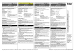
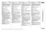
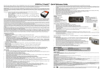
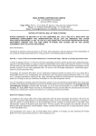
ETM770 Users Manual 201404RV01.docx
ETM770-1 2G GSM/GPRS Signal Strength Meter
ETM770-2 3G/2G HSDPA/UMTS/GSM/GPRS Signal Strength Meter
ETM770-3 3G/2G HSPA/UMTS/GSM/GPRS Signal Strength Meter
ETM770 Signal Strength Meter
User Manual
Features:
◩ LCD Display with backlight
◩ Scan for signal strength
◩ Identify network operators
◩ SMA antenna connector (FME adapter included)
◩ Internal rechargeable battery pack
◩ Mini USB connector for programming and recharging
◩ Send TCP/IP data packages to a server to confirm connectivity
Page 2 of 16
For Support Contact +61-2-9956-7377
Or [email protected]
Contents
Explanatory List of Network Abbreviations ....................................................................................... 3 Introduction ....................................................................................................................................... 4 Nomenclature ................................................................................................................................ 4 Overview. ...................................................................................................................................... 4 Applications ................................................................................................................................... 4 Interfaces .......................................................................................................................................... 4 Min USB ........................................................................................................................................ 4 SMA Antenna Connector ............................................................................................................... 4 SIM Holder .................................................................................................................................... 4 Buttons .......................................................................................................................................... 4 Charging Temperature Limitation ..................................................................................................... 5 Starting the Unit ................................................................................................................................ 5 Main Menu – 1. Scan Signal ............................................................................................................. 6 Scanning for Signal Strength ......................................................................................................... 6 Last Scan ...................................................................................................................................... 6 Neighbour Cells ............................................................................................................................. 6 Main Menu - 2. ISP Connect ............................................................................................................. 6 Set APN (Access Point Name) ...................................................................................................... 7 Set IP Address .............................................................................................................................. 7 Checking IP Connectivity .............................................................................................................. 7 Main Menu - 3. Network Operators ................................................................................................... 8 Scanning a Different Network ........................................................................................................ 8 Main Menu – 4. Status ...................................................................................................................... 9 System Details .............................................................................................................................. 9 Network ....................................................................................................................................... 10 Settings ....................................................................................................................................... 10 Main Menu – 5. Services ................................................................................................................ 11 Radio Band Region (Only Applicable to ETM770-1) ................................................................... 11 Radio Band (Restricting Scan to 2G or 3G) ................................................................................ 12 Shutdown Device ........................................................................................................................ 12 Restart Device ............................................................................................................................. 13 Using a Terminal Window to Configure the Unit ............................................................................. 13 Some Common Useful Commands to Use with Terminal Window ......................................................... 14 Troubleshooting .............................................................................................................................. 15 Error Net Login on Startup .......................................................................................................... 15 ISP Connect – Errors .................................................................................................................. 15 ETM770 Users Manual 201404RV01.Docx
Page 3 of 16
For Support Contact +61-2-9956-7377
Or [email protected]
Explanatory List of Network Abbreviations
Abbreviation
Full Name
Explanation
CHANN
Channel
Shows the ARFCN (Absolute
Frequency Channel Number)
of the Radio Band Frequency
PSC
Primary Synchronization Code
Describes start and stop time
for the time slot that the device
has been allocated
PLMN
Public Land Mobile Network
A network that is established
and operated by an
administration or by a
recognized operating agency
(ROA) for the specific purpose
of providing land mobile
telecommunications services to
the public
MCC
Mobile Country Code
The first part of the PLMN code
MNC
Mobile Network Code
The second part of the PLMN
code
LAC
Local Area Code
Identifies a Location Area
CELL
Cell ID
Cell identification number
APN
Access Point Name
Refer to Network Operator
LIP
Local IP
IP Address allocated by
Network Operator
RSCP
Received Signal Code Power
Received Signal Code Power
in dBm
SQ
Signal Quality
Quality value for base station
selection in dB
SRxL
RX level value for base station
selection in dB
ETM770 Users Manual 201404RV01.Docx
Page 4 of 16
For Support Contact +61-2-9956-7377
Or [email protected]
Introduction
Nomenclature
ETM770-1 incorporates the Cinterion TC63i engine and is intended for use worldwide.
The ETM770-2/770-3 variants incorporate the Cinterion EU3-P/PH8-P engine, both models are
intended for use in Europe, Asia, Australia and New Zealand.
Overview.
The ETM770-(x) models are signal strength meters designed for measuring the signal strength of
2G and 3G cellular operators at a particular location.
Terminal Nomenclature/History
Model
Comment
Module Installed
ETM770-1
First Release
TC63i
ETM770-2
First Release
EU3-P
ETM770-3
First Release
PH8-P
Applications
The product is typically used to:
◩ Check signal availability for a potential installation
◩ Determine the best operator for a particular location
◩ Assess antenna positioning and suitability for a particular installation
Interfaces
70.0
Min USB
The Mini USB located on the top left of the unit is used
both for programming the unit using a terminal program
as well as for charging the unit.
28.0
Mini USB
SMA Antenna
Connector
SIM Holder
Insert SIM this way up
SMA Antenna Connector
Slide catch back
before inserting SIM,
lock into position
once SIM is inserted
An SMA Jack antenna connector is located top centre of
the unit. Any suitable antenna can be connected directly
or via the use of an adaptor if required. FME adaptor
included with unit.
SIM Holder
The units SIM holder is located top right of the unit.
Please take care to ensure the unit is off when the SIM is
removed or inserted, also ensure that the SIM is inserted
correctly.
115.0
Buttons
Current Model
Older Units
ON/OFF
Scroll Up
Scroll Up
Enter
OK (enter)
Scroll Down
Scroll Down
ETM770 Users Manual 201404RV01.Docx
Page 5 of 16
For Support Contact +61-2-9956-7377
Or [email protected]
Specifications
Feature
ETM770-1
ETM770-2
ETM770-3
3G UMTS/HSDPA
Frequency Bands
N/A
850/900/2100 MHz
800/850, 900, 1900,
2100 MHz
2G GSM/GPRS Frequency
Bands
850/900/1800/1900
MHz
900/1800 MHz
850/900/1800/1900
MHz
Screen
LCD Backlit
LCD Backlit
LCD Backlit
Battery
1020 mAhr 3.7V
Rechargeable LIP
1020 mAhr 3.7V
Rechargeable LIP
1020 mAhr 3.7V
Rechargeable LIP
Battery Life
2 days operation in
typical use
2 days operation in
typical use
2 days operation in
typical use
SIM Voltage
1.8V & 3V
1.8V & 3V
1.8V & 3V
Supply Voltage
5V via Mini USB
5V via Mini USB
5V via Mini USB
Power Consumption
600mA (recharging)
600mA (recharging)
600mA (recharging)
Weight
130g
130g
130g
Operating Temperature
Range
o
o
-20 C to 40 C
o
o
-20oC to 40oC
-20 C to 40 C
Charging Temperature Limitation
In the battery charge condition of the ETM770 (when the mini –
USB connector is used), the maximum operating ambient
temperature is limited to 40˚C.
Caution
Risk of explosion if battery is
replaced by an incorrect type.
Dispose of used batteries
appropriately.
Starting the Unit
After ensuring the unit is off, insert a suitable SIM card and connect your antenna of choice. We
recommend that the SIM PIN (if applicable) is deactivated before inserting in the unit.
If the unit has sufficient charge then depressing the Enter button will start the unit.
After the unit has successfully started the following screen should appear.
ETM770 Users Manual 201404RV01.Docx
Page 6 of 16
For Support Contact +61-2-9956-7377
Or [email protected]
Main Menu – 1. Scan Signal
Scanning for Signal Strength
Use the UP and DOWN buttons to select 1. Scan Signal and then press ENTER.
Battery Indicator,
Signal Strength
1
indicates charging
Network 2G or 3G
Frequency
indicates USB connected, R indicates home network
indicates ISP connected
Scanned Network
Signal Strength in dBm and SQ value between 1 and 31 plus Average SQ
during current scan
Signal strength bar
Min and Max Signal Strength during current scan
LAC, Cell ID, PLMN and Channel ID
The above Scan Screen Indicates the Network, Frequency and Signal Strength Minimum,
Maximum and Average during the period which the scan has been active, to start a new scan
press any button and you will return to the main menu then select 1. Scan Signal again. To scan
another network see Main Menu 3. Network Operators.
Last Scan
This option will show results of the last scan that was performed.
Neighbour Cells
This option will indicate how many cells are available.
Main Menu - 2. ISP Connect
This function allows for checking an IP connection using the selected network and SIM. To use this
feature you must first set up the details of the server to be connected. The appropriate commands
can be sent from a terminal program or via SMS. If user name are required then these can only be
set via appropriate Configuration Tool contact ETM for more details.
ETM770 Users Manual 201404RV01.Docx
Page 7 of 16
For Support Contact +61-2-9956-7377
Or [email protected]
Set APN (Access Point Name)
The following commands should be used to set the APN for connection to an ISP over Internet.
ET-IAPNx=+cgdcont=1,"ip",”APN” <CR>
Both APN1 and APN2
Example: ET-IAPN1= +cgdcont=1,"ip","telstra.internet"<CR>
ET-IAPN2= +cgdcont=1,"ip","telstra.internet"<CR>
must be set.
Set IP Address
The following commands should be used to set the IP-Address for connection to a Server.
ET-IP1=” Remote Server IP-Address” : “Remote Port” <CR>
ET-IP2=” Remote Server IP-Address” : “Remote Port” <CR>
Both IP1 and IP2 must
Example: ET-IP1=144.132.166.189:2049<CR>
ET-IP2=144.132.166.189:2049<CR>
be set.
Checking IP Connectivity
Use the UP and DOWN buttons to select 2. ISP Connect and press ENTER.
Open ISP confirms that the SIM and ISP login details are correct and that a successful logon
occurs. Possible errors may come from incorrect authentication details, incorrectly configured SIM
or no signal.
Ping confirms that once logged on to the ISP a remote server can be reached.
Once ISP testing is finished use the UP and DOWN buttons to scroll to Return->Main Menu and
press ENTER.
ETM770 Users Manual 201404RV01.Docx
Page 8 of 16
For Support Contact +61-2-9956-7377
Or [email protected]
Main Menu - 3. Network Operators
Signal strength and cell information for available networks can be scanned from a SIM of any valid
network operator. Note that registration on the network and ISP connectivity testing (see above) is
only applicable for the network which provided the SIM.
Scanning a Different Network
To scan the signal from a different network, at the Main Menu use the UP and DOWN buttons to
select 3. Net Operators.
Then once the screen below is shown use the UP and DOWN buttons to select the desired
Network to be scanned.
Once the desired network is selected by pressing ENTER, the unit will wait for a response from the
network and then return to the main menu.
Once back at the main menu 1. Scan Signal can be selected and the signal strength on the new
network scanned as required.
ETM770 Users Manual 201404RV01.Docx
Page 9 of 16
For Support Contact +61-2-9956-7377
Or [email protected]
Main Menu – 4. Status
The Status section provides additional information on the current network connection as well as
details of the unit’s battery status and firmware version.
Press the UP and DOWN buttons to select 4. Status and press ENTER to access the unit status
details.
System Details
Unit details including; firmware version, hardware version, IMEI, supply and battery voltage.
Scroll down until Return appears and press Enter to return to previous menu.
ETM770 Users Manual 201404RV01.Docx
Page 10 of 16
For Support Contact +61-2-9956-7377
Or [email protected]
Network
Select Network.
Information such as cell details, relating to the network to which the unit is set will be displayed.
Scroll down until Return appears and press Enter to return to previous menu.
Settings
Select Settings.
Details of the IP address and Port to which the unit has been set (see Main Menu 2. ISP Connect)
will be displayed.
Scroll down until Return appears and press Enter to return to previous menu.
ETM770 Users Manual 201404RV01.Docx
Page 11 of 16
For Support Contact +61-2-9956-7377
Or [email protected]
Main Menu – 5. Services
The Services menu section allows you to change Radio Band Region and Radio Band as well as
Shutdown and Restart the device.
Radio Band Region (Only Applicable to ETM770-1)
Radio Band Region sets the Radio Band Groups applicable to the location you are in, for example
the applicable GSM/GPRS region for Australia is 900/1800 MHz.
NOTE – This menu item is not applicable for either the ETM770-2 or ETM770-3.
ETM770 Users Manual 201404RV01.Docx
Page 12 of 16
For Support Contact +61-2-9956-7377
Or [email protected]
Radio Band (Restricting Scan to 2G or 3G)
This section allows the selection of a specific radio band for scanning. First select Radio Band and
press ENTER.
This feature allows you
to lock the unit to a
specific band and in
effect allows you to
scan 2G or 3G
independently
The following screen will then appear.
Remember to reset to
Try All Bands, if you
want the unit to scan
for all available
services
Use the UP and DOWN buttons to select applicable band and Press ENTER, the * should move to
the selected radio band. Use the UP DOWN buttons to select Return> Main Menu and press enter.
Shutdown Device
Use this function to turn the unit off. Select Shutdown Device and press ENTER.
ETM770 Users Manual 201404RV01.Docx
Page 13 of 16
For Support Contact +61-2-9956-7377
Or [email protected]
Restart Device
Use this function if you want to restart the device. Select Restart Device and press ENTER.
Note pressing the UP and DOWN arrows together will software reset the unit.
Using a Terminal Window to Configure the Unit
Any suitable terminal program, such as Windows HyperTerminal or ETM’s own Term42 Program
(available free of charge upon request) can be used to set certain parameters in the unit.
Baud Rate is set to 9600-N-1.
Screen Shot of ETI command response using ETM Term42 program.
ETM770 Users Manual 201404RV01.Docx
Page 14 of 16
For Support Contact +61-2-9956-7377
Or [email protected]
Some Common Useful Commands to Use with Terminal Window
Command
Usage
Typical Response
ETI
To gain a quick summary of the
units status as well as
information on units firmware
version
See above example
ETSEND=AT+COPS?
To determine network & service
to which you are connected
+COPS: 1,0,"Telstra[32]Mobile
ET-I&IP
To check set server settings
et-I&ip
AT+CGDCONT?
AT+CGDCONT?
+CGDCONT:
1,"IP","internet","0.0.0.0",0,0
OK
IP STATUS:
-IPCL:TCP
APN:"internet"
LIP:0.0.0.0
RIP1:213.115.2.218:3004
RIP2:213.115.2.218:3004
Last TCP:
213.115.2.218:3004
LP:2040
Last UDP:
213.115.2.218:2049
LP:2040
OK
ET-IAPN1=
+cgdcont=1,"ip","telstra.internet"
ET-IAPN2=
+cgdcont=1,"ip","telstra.internet"
Sets APN (Access Point Name)
for network operator and SIM
used.
Must set both APN1 and APN2
Note the unit must be reset for
this command to take effect
OK
ET-IP1=144.132.166.189:2049
ET-IP2=144.132.166.189:2049
Sets the remote IP address
Must set both IP2 and IP1
Note the unit must be reset for
this command to take effect
OK
ET&SR
Software Reset
OK
Note:
If you are using SIMs that are on a VPN then a username and password are required to be set, this
can only be done via the appropriate ETM configuration tool, contact ETM for assistance.
ETM770 Users Manual 201404RV01.Docx
Page 15 of 16
For Support Contact +61-2-9956-7377
Or [email protected]
Troubleshooting
Error Net Login on Startup
Possible Causes
Further Details
Corrective Action
SIM PIN Incorrect
The Scan Signal Section can be Accessed
but will show
Deactivate SIM Pin in
handset (recommended)
Use Configuration tool to
enter SIM PIN contact ETM
for assistance
No or very weak signal
If SIM PIN okay the following start-up
screen would have been displayed
Check antenna connection
Try alternate antenna
Check network coverage
maps/information
Check Radio/Band region or
Radio Band Settings
If ETM770-2 consider trying
an alternate networks SIM
ISP Connect – Errors
Possible errors may arise from; incorrect authentication details, incorrectly configured SIM or no
signal.
Possible Causes
Further Details
Corrective Action
Incorrect ISP Login Details
ISP Dial up Login Details are incorrect
Verify APN and IP details
are correct
Ensure SIM is provisioned
correctly for data services
SIM Pin Error
See above
No or Weak Signal
See above
ETM770 Users Manual 201404RV01.Docx
ETM Matteknik AB
ETM Pacific Pty Ltd
Ekbacksvägen 32
Suite 6, 273 Alfred Street
SE-168 69 Bromma
North Sydney NSW 2060
Sweden
Australia
Tel: +46 (0)8 25 28 75
Tel: +61 (0)2 9956 7377
Fax: +46 (0)8 80 11 10
Fax: +61 (0)2 9956 5791
Email: [email protected]
Email: [email protected]
Web: www.etm.se
Web: www.etmpacific.com.au
© ETM Pacific Pty Ltd · Subject to change without notice.