1
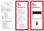
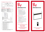
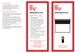
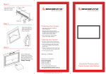
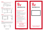
Central Control Instructions Note: Please do not operate the low voltage control frequently to prevent from damage to the relay. Wiring map Excessive motor use External Control Unit The motor will switch off if the screen is used continously for more than three minutes. Allow the motor to cool for 30 minutes before using again. If you do not expect to use your screen for some time, please disconnect the power. 6P6C (3V) Low Voltage Control RS232 Relay in-built Central Control Protocol & Control Code Data bits: 8 Digits Protecting your Screen: To ensure long lasting viewing enjoyment keep the screen rolled up when not in use. Check both the front and back surfaces before retracting into the case to make sure it is free of dust, dirt, insects or other foreign matter. Use a soft brush or cloth to lightly remove any foreign particles. Cleaning your Screen: Use warm water with a mild detergent to remove any marks on the surface (only dab, do not rub) or screen casing. Immediately dry the screen with a soft cloth or towel. Do not leave it to air dry. Initial digits: Digit 1 Stop digits: Digit 1 Baud rate: 2400 UP: 0xFF 0xEE 0xEE 0xEE 0Xdd STOP: 0xFF 0xEE 0xEE 0xEE 0Xcc DOWN: 0xFF 0xEE 0xEE 0xEE 0Xee MICRO-UP: 0xFF 0xEE 0xEE 0xEE 0xC9 MICRO-DOWN: 0xFF 0xEE 0xEE 0xEE 0xE9 Never use any solvents, chemicals or abrasive cleaners on the screen surface as they can permanently damage the screen surface. Note: Warranty does not cover un-installing or re-installing unit. Imported and Distributed in Australia by Herma Technologies Factory 4A, 6 Albert St Preston, VIC 3072 For more information please go to www.grandviewscreens.com.au or call 1300 730 025 Oct12 v1.5 Grandview Smart Screen User Manual To the owner Congratulations on purchasing a Grandview Smart Screen, This screen is designed to produce the sharpest, most pleasing pictures with maximum convenience. Before you start • • • Use the correct tools: a level, a measuring tape and a pencil to mark with. Measure the bracket position accurately before attaching to the wall or ceiling. Do not mount the brackets the full width of the casing, allow at least 100mm at each end for horizontal picture alignment. Wall mount Mount the brackets firmly eg: into wall studs or bricks. Ensure the brackets are in level. Limit settings The screen is fitted with 2 limit pots which are visible on the left had side of the motor. The YELLOW pot controls the up or down movement of the screen’s TOP limit and the WHITE pot controls the up or down movement of the BOTTOM limit. Electrical installation Grandview Smart Screens come with an Australian standard plug. Simply plug in and your screen is ready to use. Operating Instructions Using IR Remote Your remote control comes with a battery installed. To operate your remote: Press to lift the screen Press to stop the screen Press to lower the screen The Micro switch is used for retracting or lowering screen in small increments. Alternatively you may also use the external IR receiver cable and sensor. Plug the IR receiver cable into the IR socket on the casing and mount the sensor in line of sight with the remote. Now use the remote to lower and retract the screen. Undo the screen as shown below. Locking screw Caution: Before operating the screen you must remove the white adhesive tape which holds the dropper bar to the screen case. Locking piece Slide the screen onto the brackets and snap into the groove and tighten the screw. Up groove Down groove Ceiling installation Attach the ceiling brackets as shown. Slide the screen and lock Using 12V Trigger: Connect the projector and screen with the jack plug cable provided. Turn “ON” the projector and choose 12V from the menu, the screen will lower. When the projector is turned “OFF” the screen will retract into the casing. Setting the top limit The YELLOW pot is covered with a BLACK sticker to prevent accidental insertion of the HEX key which may lead you to inadvertently change the TOP limit and damage the screen. DO NOT REMOVE the BLACK sticker over the YELLOW pot under any circumstance – it will VIOD your warranty. Setting the bottom limit Caution: Setting the bottom limit beyond the black leader may render your screen inoperable and void your warranty. To access the WHITE pot, please remove the rubber grommet beneath the motor on the left-hand side of the case. Operate the screen to it reaches the bottom limit. Insert the HEY key into the WHITE pot and turning it CLOCKWISE. The screen will visibly drop by approximately 15mm steps for each rotation of the key. To raise the LOWER limit, operate the screen to it reaches the bottom limit. Insert the Hex key into the WHITE pot and turn it COUNTER-CLOCKWISE. The bottom limit will rise by approximately 15mm for each rotation of the key HOWEVER the new limit will only be visible AFTER the screen has been operated (raised and then lowered again). Using close contact Simply connect the Blue and Yellow wires to ‘L’ of control system, and the red wire to ‘N’. Then using commands in the control system, screen will open and close to it’s pre-set limits. J1 . Ensure the wall bracket is secured to the casing of the screen before hanging. EXTERNAL CTRL Projector 1 2 3 4 5 6 UP DOWN L L (Blue) N (Red) GND 6P6C Dry contact for Central control like AMX or Crestron UP and Down connect with L of Central control GND connect with N of central control Figure 22 (Yellow)