1
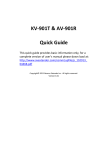
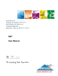
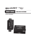
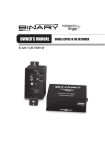
Introduction
DIP1000 HDMI with USB Over IP LAN (Multi‐cast Version) The DIP1000 system is a perfect solution to extend HDMI, USB, and optional IR/RS‐232/Remote‐Power‐On‐Off over IP networks. It includes the main units of DIP1000T transmitter and DIP1000R Receiver, as well as the below mentioned optional accessories. The DIP1000T transmitter connects with a PC or any other device with via HDMI source. The DIP1000R receiver connects to HDMI display, speaker, microphone, USB devices (Keyboard/Mouse/Storage/…) and RS232 devices. It is based on the standard Ethernet IP network. Gigabit or Fiber LAN switches can be used for inter‐connection or multi‐casting. Optional Accessories: 3.5m mini‐stereo to DB9 Female RS232 control cable 3.5m mini‐stereo to DB9 Male RS232 control cable 3.5m mini‐stereo to 2‐pins Remote Power on/off cable IR blaster cable Installation and User’s Manual For Sales and Service please contact ICP Global Pty Ltd Phone ‐ 02 9314 2092 Fax ‐ 02 9344 9537 Suite 603, Level 5, 152 Bunnerong Road PAGEOOD NSW 2035 Date: October 4, 2011
1
2
Panel View On/Off (optional) DIP1000T Transmitter 6 Link ID 7 Gigabit Ethernet 8 RS‐232 Control (optional) 9 DC 5V In 10 USB‐to‐PC 11 HDMI IN No. Component 1 HDMI Loop‐out 2 (Button 1) Description HDMI Loop‐out for Local Monitor. Press button for 1 second Press button for > 3 seconds Switch video to Remote or Loop‐out monitor. Output video to both Remote and Loop‐out monitors. Press and Hold Power ON until Green and Red LED’s start blinking 12 IR Blaster (optional) 4 bit DIP switch for 16 ID settings. To enable Transmitter/Receiver as a pair or group, the transmitter and receiver must be set with the same Link ID. For connecting directly to DIP1000R or via a Gigabyte Switch Provide Serial‐over‐IP function. System power input (DC 5V 2A) Connects this USB‐B to PC: 1. USB audio device. (USB audio device will be detected when it is attached to PC in Windows OS) 2. Virtual 4‐port USB Hub for remote USB devices. Connects to HDMI Source. For DVI source, you may need a HDMI‐to‐DVI adapter cable. Connects to external IR LED. Panel View DIP1000R Receiver Resets unit to the Factory default setting. Press button for 1 second Switch to Video or Graphic mode Anti‐Dither Mode. Setting to “Anti‐Dither 2 (Button 2) Press button for > 3 seconds Mode” to achieve better video quality for some ATI graphic cards. Press and Hold Power ON until Green LED starts blinking 3 Red LED (System) Establishes EDID from Loop‐out monitor (Power/Link) Green Blinking/Red Off: System is starting up. Green On/Red Blinking: Waiting for HDMI input source. Green On/Red On: Connection established. 5 Remote Power Connects to PC motherboard for Remote Power On/Off. 4 Green LED 3
4
No. Component 1 Green LED (Power/Link) 2 Red LED (System status) 3 Link ID Description Green Blinking/Red Off: System is starting up. For remote USB devices, such as USB KB/Mouse, storage, audio, … 5 IR Rx (optional) Remote Universal IR receiver. (optional) Stereo Audio output for the USB PnP audio device. (Set the OS default audio to the USB PnP audio device that is created by the DIP1000T) 14 Gigabit Ethernet For connecting directly to DIP1000T or via a Gigabyte Switch Green On/Red Blinking: Linking or waiting HDMI input. Green On/Red On: Connection established. 4 bit DIP switch for 16 ID settings. To enable Transmitter/Receiver as a pair or group, the transmitter and receiver must be set with the same Link ID. 4 USB Host 6 Remote Power On/Off 13 Line OUT Button for Remote PC Power On/Off function. Press button for 1 second Switch to Video or Graphic mode Anti‐Dither Mode. Setting to “Anti‐Dither 7 Mode button Press button for > 3 seconds some ATI graphic cards. Press and Hold at Power ON until Green LED blinking 8 Link button Mode” to achieve better video quality for Press button for 1 second Press button for > 3 seconds Press and Hold Power ON until Green and Red LED starts blinking Establishes EDID as the system EDID (update DIP1000T EDID) Link/Unlink To enable USB access. Resets unit to the Factory default setting. 9 DC 5V In System power input 5V 2A, or 4A when used with 4 x USB devices. 10 HDMI OUT Connects to HDMI display. For DVI display, you may need a HDMI‐to‐DVI adapter cable. 11 RS‐232 (optional) Provides Serial‐over‐IP function. 12 Mic. IN Microphone Input for the USB audio device. (Set the OS default audio device to the USB PnP audio device that is created by the DIP1000T) 5
6
2.
Installation 1.
2.
3.
4.
5.
6.
7.
8.
Ensure that the Link‐ID of both the DIP1000T and DIP1000R have the same settings. Attach the HDMI display to the DIP1000R HDMI‐Out port. Power on the DIP1000R. An “AVExtender” logo will be displayed. If this does not appear an error has occurred with either the DIP1000R, HDMI cable or the display. You can connect multiple DIP1000R’s and multiple DIP1000T units to your Gigabit Ethernet switch. Alternatively use a CAT6 UTP cable (straight, EIA 568B) to directly connect a DIP1000T with a DIP1000R as a pair. Attach the HDMI source (PC or Blue‐Ray) to the DIP1000T HDMI‐In port and then power On the DIP1000T. The first DIP1000R that is detected by the DIP1000T will gain the USB access right. If you are using your PC as your HDMI source, you will see your HDMI display EDID information on the PC graphic card control panel. If not, then something is wrong either with the DIP1000T or HDMI cable. Output HDMI (with audio) from HDMI source and check if they are correctly displayed on your HDMI display. USB over IP installation: To Use the DIP1000T Loop‐out monitor EDID: Press and Hold the Button to Power ON until the Green LED starts blinking. 3. To update the DIP1000R EDID: Press and Hold the Mode button to Power ON until Green LED is blinking. 4. To Reset the DIP1000R to the Factory default setting: Press and Hold the Link button to Power ON until Green and Red LED’s are blinking. Remote Power On/Off (optional) This function is designed for remote Power on/off control of your PC through the DIP1000R [Remote Power On/Off] push button. 1.
9.
Connect DIP1000T USB‐to‐PC port to a Windows based PC USB port by a USB‐A‐B cable. 3 devices will be detected: “Generic USB Hub”, “USB Composite Device”, “USB PnP Sound Device”. 10. Select “USB PnP Sound Device” as the Windows default sound device in order to use the speaker and microphone on the DIP1000R Line‐Out (green) and Microphone jack (pink). 11. Attach USB devices like keyboard, mouse, pen drive, audio speak/microphone … to the AV‐DIP1000R 4 USB‐A ports. Note; you will need DC 5V with 4A power adapter if all DIP1000R 4 USB ports are used. 12. To gain the USB access right among multiple DIP1000R, press and hold for more than 3 secs the “Link button” of the DIP1000R until an OSD message of “Requesting USB” is displayed, then release. An OSD message of “Starting USB” will be displayed if it successfully. Meanwhile, the previous USB Master unit will show an OSD message “USB Stopping”.
Connect the 3.5 mm plug of the supplied control cable into the DIP1000T Transmitter [Remote Power on/off] socket. 2. At the other end of the control cable, there are 2 x separated 2‐pins holders. Connect any one to your PC board [Power Reset] jumper, and the other holder connects to your PC Reset button cable. 3. On the front panel of the DIP1000R Receiver, press the [Remote Power On/Off] button. You can then remote Power Off your PC. By pressing the button again, it will turn on your PC again. RS‐232 Control (optional) This function is designed for remote access and control of your RS‐232 device. Reset to Factory default and EDID Operation 1.
To Reset the DIP1000T to the Factory default setting: Press and Hold the Button 1 then Power ON until Green and Red LED blinking. 7
8
1. Connect the 3.5mm mini‐stereo plug of the supplied RS‐232 cable to the [RS‐232] socket at the rear panel of the DIP1000T Transmitter, and then connect the DB9 Female connector of the supplied RS‐232 cable to the COM port of your PC. 2. Connect the 3.5mm mini‐stereo plug of the supplied RS‐232 cable to the [RS‐232] socket at the rear panel of the DIP1000R Receiver, and then connect the DB9 Male connector of the supplied RS‐232 cable to the RS‐232 device. RS232 Pin Assignments Signal ‐NC‐ TxD RxD ‐NC‐ ‐NC‐ ‐NC‐
‐NC‐
‐NC‐
‐NC‐
DIP1000R 5 3 2 7 8 4 6 1 9 DIP1000T 5 2 3 8 7 6 4 1 9 Infrared Control (optional) This function is designed to transmit IR signal from the DIP1000R to the AV sources. 1. Connect the supplied IR blaster cable to the [IR blaster] socket at the rear panel of the DIP1000T Transmitter. Please check if the LED on the IR blaster is correctly positioned in the front of the AV sources. 2. Make sure your infrared remote controller is able to align the DIP1000R [IR Rx] port. When you press any key on the remote controller, the DIP1000R receives the IR signal and transmits it to the DIP1000T. Then the IR signal is delivered to the AV sources device through the LED on the IR blaster cable. 3. The LED of the IR blaster cable must be facing the IR receiver of your Windows Media Center Edition PC, TV tuner card or Blu‐Ray player.
9