1
Thyristor Power units
and
Driver units
Thyristor Power units
and
Driver units
470
series
470
series
Single-phase resistive and
inductive load
true power control
Single-phase resistive and
inductive load
true power control
User
Manual
User
Manual
© Copyright Eurotherm Automation 1996
© Copyright Eurotherm Automation 1996
All rights reserved. All reproduction or transmission in any form or using any procedure (electronic or mechanical, including photocopying and
recording) without the written permission of EUROTHERM AUTOMATION is strictly prohibited. EUROTHERM AUTOMATION have taken
particular care to ensure the accuracy of these specifications. However, in order to maintain our technological lead, we are dedicated to the
continual improvement of our products and this may lead to modifications or omissions in the current specifications. We cannot be held
responsible for any material or bodily damage, losses or costs incurred.
Printed in France 05/96
Printed in France 05/96
HA 175076 Issue 1
HA 175076 Issue 1
The installation, configuration, commissioning and maintenance of the power unit
must only be performed by a person qualified and authorised to perform work
in an industrial low voltage electrical environment.
The installation, configuration, commissioning and maintenance of the power unit
must only be performed by a person qualified and authorised to perform work
in an industrial low voltage electrical environment.
Important precautions and special information are indicated in the manual by
two symbols:
Important precautions and special information are indicated in the manual by
two symbols:
WARNING
!
CAUTION
This symbol means that failure to take note of the
information may have serious consequences for the
safety of personnel and may even result in the risk
of electrocution.
This symbol means that failure to take note of the
information may
• have serious consequences for the installation
• result in the incorrect functioning of the power unit.
These marks must indicate specific points.
The entire manual remains applicable.
These marks must indicate specific points.
The entire manual remains applicable.
It is the responsibility of the user and it is highly recommended, given the value
of the equipment controlled using 470, to install independent safety devices.
It is the responsibility of the user and it is highly recommended, given the value
of the equipment controlled using 470, to install independent safety devices.
This alarm must be tested regularly.
This alarm must be tested regularly.
Eurotherm can supply suitable equipment.
Eurotherm can supply suitable equipment.
As a result of the constant improvement of its products, Eurotherm
may modify these specifications without warning.
For any further information and if in doubt, please contact your EUROTHERM
office where technicians are at your disposal should you require advice or
assistance with the commissioning of your installation.
Printed in France 05/96
Printed in France 05/96
HA 175076 Issue 1
HA 175076 Issue 1
EUROPEAN DIRECTIVES
EUROPEAN DIRECTIVES
ELECTROMAGNETIC COMPATIBILITY (EMC)
ELECTROMAGNETIC COMPATIBILITY (EMC)
For industrial environments, excluding residential environments
For industrial environments, excluding residential environments
The 470 products are considered as components without any direct
function as defined in the EMC Directive. The system or installation in which
these products are incorporated must complies with the essential protection
requirements of the EMC Directive.
The 470 products are considered as components without any direct
function as defined in the EMC Directive. The system or installation in which
these products are incorporated must complies with the essential protection
requirements of the EMC Directive.
However, Eurotherm certifies that the 470 products, when installed
and used in accordance with their User Manual, meets the following test standards
and enables the system or installation in which there are installed to comply
with the EMC Directive in regards to the 470 products.
However, Eurotherm certifies that the 470 products, when installed
and used in accordance with their User Manual, meets the following test standards
and enables the system or installation in which there are installed to comply
with the EMC Directive in regards to the 470 products.
Tests
Immunity Electrostatic discharge
Fast transients
Radioelectric frequency
electromagnetic fields
Emission Radiated
Conducted
(the choice of the applicable
standard depends on the
application)
Test standards
Edition
IEC 1000-4-2 (EN 61000-4-2)
IEC 1000-4-4 (EN 61000-4-4)
IEC 801-3 (prEN 61000-4-3)
06/1995
01/1995
1984
EN 55011
EN 50081-2
1991
1991
With an external filter
IEC 1800-3 (prEN 61800-3)
1996
Without external filter.
Applies for the second environment
In order to guarantee the best service, Eurotherm has validated the compliance of
the 470 products with these test standards through design and laboratory
tests that have been validated with a Technical Construction File by a Competent
Body, LCIE (Laboratoire Central des Industries Électriques).
EXTERNAL SERIES FILTERS
25 A to 60 A
75 A and 100 A
150 A
Printed in France 05/96
Immunity Electrostatic discharge
Fast transients
Radioelectric frequency
electromagnetic fields
Emission Radiated
Conducted
(the choice of the applicable
standard depends on the
application)
Test standards
Edition
IEC 1000-4-2 (EN 61000-4-2)
IEC 1000-4-4 (EN 61000-4-4)
IEC 801-3 (prEN 61000-4-3)
06/1995
01/1995
1984
EN 55011
EN 50081-2
1991
1991
With an external filter
IEC 1800-3 (prEN 61800-3)
1996
Without external filter.
Applies for the second environment
In order to guarantee the best service, Eurotherm has validated the compliance of
the 470 products with these test standards through design and laboratory
tests that have been validated with a Technical Construction File by a Competent
Body, LCIE (Laboratoire Central des Industries Électriques).
EXTERNAL SERIES FILTERS
To reduce the conducted emissions that occur when using thyristor units, Eurotherm can
supply external filters.
Nominal current of 470
Tests
Serial filter order code
FILTER/TRI/63A/00
FILTER/TRI/100A/00
FILTER/TRI/160A/00
HA 175076 Issue 1
To reduce the conducted emissions that occur when using thyristor units, Eurotherm can
supply external filters.
Nominal current of 470
25 A to 60 A
75 A and 100 A
150 A
Printed in France 05/96
Serial filter order code
FILTER/TRI/63A/00
FILTER/TRI/100A/00
FILTER/TRI/160A/00
HA 175076 Issue 1
SAFETY
SAFETY
The
470
products
installed
and
used
in accordance with this User Manual are designed
to comply with the essential protection requirements of
the Low Voltage Directive 73/23EEC dated 19/02/73
(amended by Directive 93/68/EEC dated 22/07/93).
The
470
products
installed
and
used
in accordance with this User Manual are designed
to comply with the essential protection requirements of
the Low Voltage Directive 73/23EEC dated 19/02/73
(amended by Directive 93/68/EEC dated 22/07/93).
MARK
MARK
The CE Mark of 470 products implies
the essential protection requirements of
Low Voltage Directive are observed.
that
the
The CE Mark of 470 products implies
the essential protection requirements of
Low Voltage Directive are observed.
that
the
The 470 Technical Construction File is approved by a Notified
Body, LCIE (Laboratoire Central des Industries
Électriques).
The 470 Technical Construction File is approved by a Notified
Body, LCIE (Laboratoire Central des Industries
Électriques).
DECLARATION OF CONFORMITY
DECLARATION OF CONFORMITY
A CE Declaration of Conformity is available on request.
A CE Declaration of Conformity is available on request.
FURTHER INFORMATION
FURTHER INFORMATION
For further information on CE Mark, please contact your
nearest Eurotherm office.
Printed in France 05/96
For further information on CE Mark, please contact your
nearest Eurotherm office.
HA 175076 Issue 1
Printed in France 05/96
HA 175076 Issue 1
This 470 User Manual (Part No. HA 174836) intends
for the 470 series power thyristor units manufactured
from May 1996.
This 470 User Manual (Part No. HA 174836) intends
for the 470 series power thyristor units manufactured
from May 1996.
The 470 User Manual ( Part No. HA 020134) is valid for
products manufactured before this date.
The 470 User Manual ( Part No. HA 020134) is valid for
products manufactured before this date.
In order to help you reduce risks related to the effects
of electromagnetic interference depending on the
installation of the product, Eurotherm can supply you
with the "EMC Installation Guide"
(Part No. HA 025464).
In order to help you reduce risks related to the effects
of electromagnetic interference depending on the
installation of the product, Eurotherm can supply you
with the "EMC Installation Guide"
(Part No. HA 025464).
This guide gives the rules generally applicable for
Electromagnetic compatibility.
This guide gives the rules generally applicable for
Electromagnetic compatibility.
Manufactured by Eurotherm Automation S.A.
ISO 9001 - EN 29001 certified
Manufactured by Eurotherm Automation S.A.
ISO 9001 - EN 29001 certified
Printed in France 05/96
HA 175076 Issue 1
Printed in France 05/96
HA 175076 Issue 1
470 USER MANUAL
470 USER MANUAL
The safety instructions for the installation and use of 470 series units are
given in the pages below:
•
•
•
•
•
•
installation
wiring
configuration
commissioning
fuse protection
maintenance
2-2, 2-4
3-2, 3-11, 3-13, 3-14, 3-24
4-2
6-2, 6-10
7-2,7-4
7-5
Contents
Chapter 1
The safety instructions for the installation and use of 470 series units are
given in the pages below:
•
•
•
•
•
•
IDENTIFYING THE THYRISTOR UNITS
Page
Chapter 1
INSTALLATION
Chapter 2
Cont.1
IDENTIFYING THE THYRISTOR UNITS
Page
General introduction to the 470 series .......................... 1-2
Technical data ............................................................... 1-6
Power ......................................................................... 1-6
Environment ............................................................... 1-6
Control ........................................................................ 1-7
Retransmissions ......................................................... 1-8
Current limit ................................................................ 1-8
Power limit .................................................................. 1-8
Partial load failure detection ....................................... 1-8
Thyristor unit coding ...................................................... 1-9
Backplate ................................................................. 1-10
Short or full code ...................................................... 1-10
Coding example .......................................................... 1-11
470 series thyristor unit and
installation parameters ............................................ 1-11
Thyristor unit coding ................................................. 1-11
Serial number labels ................................................... 1-12
Safety during installation ............................................... 2-2
Dimensions ................................................................... 2-3
Mechanical mounting .................................................... 2-4
470 User Manual
2-2, 2-4
3-2, 3-11, 3-13, 3-14, 3-24
4-2
6-2, 6-10
7-2,7-4
7-5
Contents
General introduction to the 470 series .......................... 1-2
Technical data ............................................................... 1-6
Power ......................................................................... 1-6
Environment ............................................................... 1-6
Control ........................................................................ 1-7
Retransmissions ......................................................... 1-8
Current limit ................................................................ 1-8
Power limit .................................................................. 1-8
Partial load failure detection ....................................... 1-8
Thyristor unit coding ...................................................... 1-9
Backplate ................................................................. 1-10
Short or full code ...................................................... 1-10
Coding example .......................................................... 1-11
470 series thyristor unit and
installation parameters ............................................ 1-11
Thyristor unit coding ................................................. 1-11
Serial number labels ................................................... 1-12
Chapter 2
installation
wiring
configuration
commissioning
fuse protection
maintenance
INSTALLATION
Safety during installation ............................................... 2-2
Dimensions ................................................................... 2-3
Mechanical mounting .................................................... 2-4
470 User Manual
Cont.1
Contents (Continued)
Chapter 3
Page
WIRING
Contents (Continued)
Chapter 3
Safety during wiring ..................................................................... 3-2
Fixing the power cables .............................................................. 3-3
User terminal blocks .................................................................... 3-5
Auxiliary power supply ........................................................ 3-6
Alarm relay contact ............................................................. 3-7
Load voltage information ..................................................... 3-8
Control cables ............................................................................. 3-9
Fixing ................................................................................... 3-9
Connecting the shield to the ground ................................... 3-10
Control terminal block ................................................................. 3-11
Driver terminal block ................................................................... 3-13
Input signals ................................................................................ 3-14
Safety quench ..................................................................... 3-14
Inhibit ................................................................................... 3-14
External control connection ................................................. 3-15
Control of multiple thyristor units .................................... 3-16
Parallel input connection ............................................ 3-16
Serial input connection ............................................... 3-16
Manual control connection .................................................. 3-17
Current limit connection (optional) ...................................... 3-18
Limit set using the potentiometer on the front panel ....... 3-18
Limit set using an external voltage ................................. 3-19
Limit set using an external potentiometer ......................... 3-20
Power limit connection ........................................................ 3-21
Limit set using the potentiometer on the front panel ....... 3-21
Limit set using an external potentiometer ......................... 3-22
Limit set using an external voltage ................................. 3-22
Retransmission signals ....................................................... 3-23
External thyristor block control (472 model) ........................ 3-24
Examples of wiring diagrams ...................................................... 3-26
470 and 471 model thyristor units ....................................... 3-26
Driver unit, 472 model ......................................................... 3-28
Cont.2
470 User Manual
Page
WIRING
Safety during wiring ..................................................................... 3-2
Fixing the power cables .............................................................. 3-3
User terminal blocks .................................................................... 3-5
Auxiliary power supply ........................................................ 3-6
Alarm relay contact ............................................................. 3-7
Load voltage information ..................................................... 3-8
Control cables ............................................................................. 3-9
Fixing ................................................................................... 3-9
Connecting the shield to the ground ................................... 3-10
Control terminal block ................................................................. 3-11
Driver terminal block ................................................................... 3-13
Input signals ................................................................................ 3-14
Safety quench ..................................................................... 3-14
Inhibit ................................................................................... 3-14
External control connection ................................................. 3-15
Control of multiple thyristor units .................................... 3-16
Parallel input connection ............................................ 3-16
Serial input connection ............................................... 3-16
Manual control connection .................................................. 3-17
Current limit connection (optional) ...................................... 3-18
Limit set using the potentiometer on the front panel ....... 3-18
Limit set using an external voltage ................................. 3-19
Limit set using an external potentiometer ......................... 3-20
Power limit connection ........................................................ 3-21
Limit set using the potentiometer on the front panel ....... 3-21
Limit set using an external potentiometer ......................... 3-22
Limit set using an external voltage ................................. 3-22
Retransmission signals ....................................................... 3-23
External thyristor block control (472 model) ........................ 3-24
Examples of wiring diagrams ...................................................... 3-26
470 and 471 model thyristor units ....................................... 3-26
Driver unit, 472 model ......................................................... 3-28
Cont.2
470 User Manual
Contents (Continued)
Chapter 4
CONFIGURATION
Contents (Continued)
Page
Chapter 4
CONFIGURATION
Safety during configuration ................................................... 4-2
Location of the configuration equipment ............................... 4-3
Configuration of the control board ......................................... 4-6
Input type ........................................................................... 4-6
Automatic input (external signal) .................................... 4-6
Manual input ................................................................... 4-6
Thyristor firing mode .......................................................... 4-7
Frequency .......................................................................... 4-7
Configuration of the driver board ........................................... 4-8
Chapter 5
OPERATION
Thyristor firing modes ............................................................ 5-2
General ............................................................................. 5-2
'Phase angle' mode .......................................................... 5-2
'Burst firing' mode ............................................................. 5-3
'Single cycle' mode ........................................................ 5-3
Modulation time ............................................................. 5-4
Soft start / end ............................................................... 5-5
Over-current elimination for the inductive load ................. 5-6
Control ................................................................................... 5-7
Control function ................................................................ 5-7
Pulse gating ...................................................................... 5-9
Power limit ........................................................................... 5-10
Current limit (optional) ......................................................... 5-11
Partial load failure detection ................................................ 5-12
Retransmission ................................................................... 5-13
Load current image ..................................................... 5-13
Load voltage image ..................................................... 5-13
True power image ....................................................... 5-13
Inhibit and safety quench .................................................... 5-14
470 User Manual
Cont.3
Page
Thyristor firing modes ............................................................ 5-2
General ............................................................................. 5-2
'Phase angle' mode .......................................................... 5-2
'Burst firing' mode ............................................................. 5-3
'Single cycle' mode ........................................................ 5-3
Modulation time ............................................................. 5-4
Soft start / end ............................................................... 5-5
Over-current elimination for the inductive load ................. 5-6
Control ................................................................................... 5-7
Control function ................................................................ 5-7
Pulse gating ...................................................................... 5-9
Power limit ........................................................................... 5-10
Current limit (optional) ......................................................... 5-11
Partial load failure detection ................................................ 5-12
Retransmission ................................................................... 5-13
Load current image ..................................................... 5-13
Load voltage image ..................................................... 5-13
True power image ....................................................... 5-13
Inhibit and safety quench .................................................... 5-14
470 User Manual
Cont.3
Contents (Continued)
Page
Chapter 6 COMMISSIONING PROCEDURE
Contents (Continued)
Chapter 6 COMMISSIONING PROCEDURE
Commissioning procedure safety .............................................. 6-2
Checking the characteristics ..................................................... 6-3
Load current ........................................................................... 6-3
Power supply voltage ............................................................. 6-3
Auxiliary supply voltage ......................................................... 6-3
Input signals ........................................................................... 6-3
Partial load failure detection .................................................. 6-3
External thyristor blocks ......................................................... 6-3
Diagnostic unit ........................................................................... 6-4
Calibration ................................................................................. 6-9
Preliminary settings ................................................................. 6-10
Default position of potentiometer P4 ................................... 6-11
Resistive load with low resistance variations ....................... 6-11
Resistive load with high resistance variations ..................... 6-11
Non-saturating inductive load .............................................. 6-12
Saturating inductive load ..................................................... 6-12
Partial load failure detection setting ........................................ 6-14
Current limit setting (optional) ................................................. 6-15
Power limit ............................................................................... 6-16
Checks in the event of abnormal operation ............................ 6-17
Chapter 7 MAINTENANCE
Thyristor protection .................................................................. 7-2
Thyristor protection fuse ........................................................... 7-3
Replacement of the internal high speed fuse ........................... 7-4
Auxiliary power supply protection fuses ................................... 7-4
Servicing .................................................................................. 7-5
Tools ........................................................................................ 7-6
Cont.4
Page
470 User Manual
Thyristor protection .................................................................. 7-2
Thyristor protection fuse ........................................................... 7-3
Replacement of the internal high speed fuse ........................... 7-4
Auxiliary power supply protection fuses ................................... 7-4
Servicing .................................................................................. 7-5
Tools ........................................................................................ 7-6
Cont.4
470 User Manual
Identification
Identification
Chapter 1
Chapter 1
IDENTIFYING THE THYRISTOR UNITS
IDENTIFYING THE THYRISTOR UNITS
Contents
page
Contents
General introduction to the 470 series .......................... 1-2
Technical data ............................................................... 1-6
Power ......................................................................... 1-6
Environment ............................................................... 1-6
Control ........................................................................ 1-7
Retransmissions ......................................................... 1-8
Current limit ................................................................ 1-8
Power limit .................................................................. 1-8
Partial load failure detection ....................................... 1-8
Thyristor unit coding ...................................................... 1-9
Backplate ................................................................. 1-10
Short or full code ...................................................... 1-10
Coding example .......................................................... 1-11
470 series thyristor unit and
installation parameters ............................................ 1-11
Thyristor unit coding ................................................. 1-11
Serial number labels ................................................... 1-12
470 User Manual
page
General introduction to the 470 series .......................... 1-2
Technical data ............................................................... 1-6
Power ......................................................................... 1-6
Environment ............................................................... 1-6
Control ........................................................................ 1-7
Retransmissions ......................................................... 1-8
Current limit ................................................................ 1-8
Power limit .................................................................. 1-8
Partial load failure detection ....................................... 1-8
Thyristor unit coding ...................................................... 1-9
Backplate ................................................................. 1-10
Short or full code ...................................................... 1-10
Coding example .......................................................... 1-11
470 series thyristor unit and
installation parameters ............................................ 1-11
Thyristor unit coding ................................................. 1-11
Serial number labels ................................................... 1-12
1-1
470 User Manual
1-1
Identification
Identification
Chapter 1 IDENTIFYING THE THYRISTOR UNITS
Chapter 1 IDENTIFYING THE THYRISTOR UNITS
GENERAL INTRODUCTION TO THE 470 SERIES
GENERAL INTRODUCTION TO THE 470 SERIES
The 470 series power thyristor units are true power controllers of single-phase industrial
electrical loads.
The 470 series power thyristor units are true power controllers of single-phase industrial
electrical loads.
The 470 series is designed for the true power control of:
• inductive and transformer connected loads (transformer primary circuits, in particular) or
• high or low temperature coefficient resistive loads.
The 470 series is designed for the true power control of:
• inductive and transformer connected loads (transformer primary circuits, in particular) or
• high or low temperature coefficient resistive loads.
The 470 series is composed of three models:
The 470 series is composed of three models:
• 470 : power thyristor unit with incorporated thyristors;
nominal current: 15 A to 75 A; natural convection cooling.
• 471 : power thyristor unit with incorporated thyristors;
nominal current: 100 A to 150 A; fan cooling.
• 472 : external thyristor driver unit;
nominal current of driven thyristor block up to 4000 A;
external current transformer (secondary current 5A nominal).
The nominal line-to-line voltage is 100 V to 500 V.
The nominal line-to-line voltage is 100 V to 500 V.
The control signal, which can be reconfigured by the user, can have one of three voltage levels:
0-5 V ; 0-10 V and 1-5 V.
or one of four current levels:
0-5 mA ; 0-10 mA ; 0-20 mA and 4-20 mA.
Manual control using external potentiometers is possible.
The control signal, which can be reconfigured by the user, can have one of three voltage levels:
0-5 V ; 0-10 V and 1-5 V.
or one of four current levels:
0-5 mA ; 0-10 mA ; 0-20 mA and 4-20 mA.
Manual control using external potentiometers is possible.
Three load parameters can be controlled:
true power (P), squared RMS voltage (V2 ), or squared RMS current (I2 ).
Three load parameters can be controlled:
true power (P), squared RMS voltage (V2 ), or squared RMS current (I2 ).
The 470 series thyristor units are equipped with the following functions:
The 470 series thyristor units are equipped with the following functions:
• different thyristor firing modes
• decrease in the current requirements of high temperature coefficient loads
using current limits and soft starts
• elimination of over-currents when starting non-saturating inductive and
transformer connected loads
• current limit (optional) and controlled parameter limit
• partial load failure detection
• pulse gating circuit
• inhibit and safety quench
• load current, voltage and power image retransmission.
1-2
470 User Manual
Identification
Identification
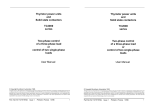
User terminal blocks
EUROTHERM
C
Lh
oa
ar
dg
e
Fail
Défaut
Adjust
Seuil
Test
P.Limit
P.Limit.
I limit
Limit. I
P.Adjust
P.Régl.
Fuse fail
Diagnostic
socket
(Left)
Déf. fusible
Diagnostic
socket
(Right)
240 V ~ 75 A
L
Control cable
clamp
Heatsink Control cable
clamp
Power terminals
Figure 1-1 Overall view of the 470 series thyristor unit
470 User Manual
Figure 1-1 Overall view of the 470 series thyristor unit
1-3
470 User Manual
1-3
Identification
Identification
The 470 series thyristor units are fitted with:
1-4
The 470 series thyristor units are fitted with:
• a 'control board' which generates the input signals and controls the parameter measured
by the driver board;
• a 'control board' which generates the input signals and controls the parameter measured
by the driver board;
• a 'driver board' which controls the true power of the load using the load voltage and
current measurements and retransmits the controlled parameter (DC voltage) and the
load voltage and current (instant AC values);
for the 472 model, this board generates the external thyristor firing signals;
• a 'driver board' which controls the true power of the load using the load voltage and
current measurements and retransmits the controlled parameter (DC voltage) and the
load voltage and current (instant AC values);
for the 472 model, this board generates the external thyristor firing signals;
• a 'neutral board' to connect the reference neutral or phase (depending on wiring);
• a 'neutral board' to connect the reference neutral or phase (depending on wiring);
• an 'RC snubber board' which protects the thyristors from fast voltage variations and
generates the thyristor firing pulses;
this board has a thyristor pulse gating circuit to prevent unstable firing in
certain applications.
• an 'RC snubber board' which protects the thyristors from fast voltage variations and
generates the thyristor firing pulses;
this board has a thyristor pulse gating circuit to prevent unstable firing in
certain applications.
The control system controls the true power, the squared voltage or the squared load current as a
function of an input signal and the selected feedback parameter.
The control system controls the true power, the squared voltage or the squared load current as a
function of an input signal and the selected feedback parameter.
The soft start (in thyristor firing angle variation) for high temperature coefficient resistive
loads and the delayed firing angle at the first half-cycle for the control of inductive and
transformer connected loads minimise transient over-currents.
The soft start (in thyristor firing angle variation) for high temperature coefficient resistive
loads and the delayed firing angle at the first half-cycle for the control of inductive and
transformer connected loads minimise transient over-currents.
The soft start (or end) duration can be set from 0 to 0.25 s per potentiometer located on the
control board.
The soft start (or end) duration can be set from 0 to 0.25 s per potentiometer located on the
control board.
The 470 series thyristor units are equipped with a power limit and, as an option, a current limit
(only available in Phase angle firing and Burst firing with soft start modes).
The 470 series thyristor units are equipped with a power limit and, as an option, a current limit
(only available in Phase angle firing and Burst firing with soft start modes).
The partial load failure detection circuit (PLF) detects a 25 % increase in the load impedance
(independently of the power supply voltage variation).
The partial load failure detection circuit (PLF) detects a 25 % increase in the load impedance
(independently of the power supply voltage variation).
The partial load failure detection circuit (PLF alarm) is set using a front panel potentiometer for
the real current of the load used. The PLF alarm is signalled by the alarm relay contact and by
the 'Load fail' indicator light on the front panel.
The partial load failure detection circuit (PLF alarm) is set using a front panel potentiometer for
the real current of the load used. The PLF alarm is signalled by the alarm relay contact and by
the 'Load fail' indicator light on the front panel.
470 User Manual
1-4
470 User Manual
Identification
The 470 thyristor units have the following thyristor firing modes:
The 470 thyristor units have the following thyristor firing modes:
• thyristor firing angle variation ('Phase angle'),
• cyclic firing ratio modulation from 0 to 100 % ('Burst mode').
• thyristor firing angle variation ('Phase angle'),
• cyclic firing ratio modulation from 0 to 100 % ('Burst mode').
'Burst mode' firing is characterised by different modes:
•
•
•
•
•
Identification
'Burst mode' firing is characterised by different modes:
one firing or non-firing cycle ('Single cycle')
slow cycle (modulation time 8 s at 50% setpoint)
fast cycle (modulation time 0.8 s at 50% setpoint)
burst firing (fast or slow) with soft start in thyristor firing angle variation
burst firing (fast or slow) with soft start and end in thyristor firing angle variation.
•
•
•
•
•
The front panel comprises the following:
one firing or non-firing cycle ('Single cycle')
slow cycle (modulation time 8 s at 50% setpoint)
fast cycle (modulation time 0.8 s at 50% setpoint)
burst firing (fast or slow) with soft start in thyristor firing angle variation
burst firing (fast or slow) with soft start and end in thyristor firing angle variation.
The front panel comprises the following:
•
•
•
•
•
the partial load failure detection setting potentiometer
the 'Test' push button to test the partial load failure alarm setting
the indicator light to display the partial load failure detection
the current limit setting potentiometer (optional)
the indicator to display an internal thyristor protection fuse blow-out
(470 and 471 models)
• the sockets (left and right) for diagnostics.
• the power limit setting potentiometer
• the calibration potentiometer
•
•
•
•
•
the partial load failure detection setting potentiometer
the 'Test' push button to test the partial load failure alarm setting
the indicator light to display the partial load failure detection
the current limit setting potentiometer (optional)
the indicator to display an internal thyristor protection fuse blow-out
(470 and 471 models)
• the sockets (left and right) for diagnostics.
• the power limit setting potentiometer
• the calibration potentiometer
The 471 model thyristor units are equipped with a fan (100 A to 150 A nominal).
The 471 model thyristor units are equipped with a fan (100 A to 150 A nominal).
Thermal protection is provided by a thermal switch which detects if the fan has stopped or
the heatsink is overheated and inhibits thyristor unit firing.
Thermal protection is provided by a thermal switch which detects if the fan has stopped or
the heatsink is overheated and inhibits thyristor unit firing.
The 470 thyristor unit is equipped with an active operation inhibit.
An external 10 V voltage (32 V max) or a contact connected to the control terminal block is
used to inhibit the thyristor unit.
The 470 thyristor unit is equipped with an active operation inhibit.
An external 10 V voltage (32 V max) or a contact connected to the control terminal block is
used to inhibit the thyristor unit.
The 470 series thyristor units can be plugged into the mounting backplate.
The 470 series thyristor units can be plugged into the mounting backplate.
470 User Manual
1-5
470 User Manual
1-5
Identification
Identification
TECHNICAL DATA
TECHNICAL DATA
The 470 series power thyristor units are designed to control the true power of an industral
single-phase load with a high current requirement at start-up using thyristors.
!
Caution !
It is the user's responsibility to ensure that the thyristor unit nominal values are compatible
with the conditions of installation and operation before commissioning the thyristor unit.
Power
Nominal current
Nominal line-to-line voltage
Power supply frequency
Dissipated power
Cooling
Fan
Thyristor protection
Load
Residual current
External wiring
15 A to 150 A (internal thyristors).
Up to 4000 A (external thyristor block)
100 Vac to 500 Vac (+10%,-15%)
Inhibit below 70% of the nominal voltage;
return to 85 % of the nominal value
50 Hz or 60 Hz (±2 Hz)
1.3 W (approximately) per ampere (470 and 471 models)
Permanent fan cooling above 100 A nominal
Consumption 23 VA (471 model)
Powered by the auxiliary power supply voltage
Internal high speed fuse (15 A to 125 A nominal)
External fuse for 150 A nominal (471 model)
Varistor and RC snubber circuit
Single-phase resistive with high temperature coefficient
or nductive or tranformer connected
In the OFF state,typically below 30 mA (internal thyristors)
To be performed according to the standards IEC 364
Environment
Mounting
Operating temperature
Storage temperature
Protection
Operating atmosphere
Humidity
Pollution
Electromagnetic compatibility
(the product installed and used
in accordance with User Manual,
see European Directives chapter)
Electrical safety
CE Mark
1-6
The 470 series power thyristor units are designed to control the true power of an industral
single-phase load with a high current requirement at start-up using thyristors.
!
Caution !
It is the user's responsibility to ensure that the thyristor unit nominal values are compatible
with the conditions of installation and operation before commissioning the thyristor unit.
Power
Nominal current
Nominal line-to-line voltage
Power supply frequency
Dissipated power
Cooling
Fan
Thyristor protection
Load
Residual current
External wiring
15 A to 150 A (internal thyristors).
Up to 4000 A (external thyristor block)
100 Vac to 500 Vac (+10%,-15%)
Inhibit below 70% of the nominal voltage;
return to 85 % of the nominal value
50 Hz or 60 Hz (±2 Hz)
1.3 W (approximately) per ampere (470 and 471 models)
Permanent fan cooling above 100 A nominal
Consumption 23 VA (471 model)
Powered by the auxiliary power supply voltage
Internal high speed fuse (15 A to 125 A nominal)
External fuse for 150 A nominal (471 model)
Varistor and RC snubber circuit
Single-phase resistive with high temperature coefficient
or nductive or tranformer connected
In the OFF state,typically below 30 mA (internal thyristors)
To be performed according to the standards IEC 364
Environment
In closed metal cabinet
0°C to +50°C in vertical position in altitude 2000 m maxi
-10°C to +70°C
IP00 (can be opened without tools according to IEC 364)
Non-explosive, non-corrosive and non-conducting
RH of 5% to 95% without condensation
Degree 2 admissible, defined by IEC 664
Immunity : comply with Standards EN 61000-4-2,
EN 61000-4-4, EN 61000-4-3
Radiated emission : comply with EN 55011
Conducted emission :
comply with EN 50081-2 (with an external filter),
comply with EN 61800-3 (without external filter).
Comply with Low Voltag Directive 73/23/EEC
The 470 products are CE marked
(see European Directives chapter).
470 User Manual
Mounting
Operating temperature
Storage temperature
Protection
Operating atmosphere
Humidity
Pollution
Electromagnetic compatibility
(the product installed and used
in accordance with User Manual,
see European Directives chapter)
Electrical safety
CE Mark
1-6
In closed metal cabinet
0°C to +50°C in vertical position in altitude 2000 m maxi
-10°C to +70°C
IP00 (can be opened without tools according to IEC 364)
Non-explosive, non-corrosive and non-conducting
RH of 5% to 95% without condensation
Degree 2 admissible, defined by IEC 664
Immunity : comply with Standards EN 61000-4-2,
EN 61000-4-4, EN 61000-4-3
Radiated emission : comply with EN 55011
Conducted emission :
comply with EN 50081-2 (with an external filter),
comply with EN 61800-3 (without external filter).
Comply with Low Voltag Directive 73/23/EEC
The 470 products are CE marked
(see European Directives chapter).
470 User Manual
Identification
Control
Control supply
Signal type
Setpoint
Input impedance
Manual control
Thyristor firing modes
Transient current
elimination
Identification
Control
Control supply
Connection of the auxiliary power supply to the user
terminal block.
Consumption: 7 VA (470 and 472 model) 30 VA (471 model)
Analogue
Voltage: 0-5 V; 1-5 V or 0-10 V
Current: 0-5 mA ; 0-10 mA ; 0-20 mA or 4-20 mA
Voltage:
> 50 kΩ
Current:
250 Ω or 1000 Ω (depending on configuration)
10 kΩ external potentiometer
Signal type
Setpoint
Input impedance
Manual control
The following can be reconfigured by the user:
• Phase angle
• Single cycle (burst firing with a firing or non-firing cycle)
• Fast cycle
(typical modulation time at 50 % power : 0.8 s)
• Slow cycle
(typical modulation time at 50 % power : 8 s)
• Fast cycle with adjustable soft start between
0 and 250 ms (with or without soft end)
• Slow cycle with adjustable soft start between
0 and 250 ms (with or without soft end)
Thyristor firing modes
Transient current
elimination
Delayed firing of the 1st burst half-cycle (without soft operation)
for non-saturating inductive and transformer connected loads
Connection of the auxiliary power supply to the user
terminal block.
Consumption: 7 VA (470 and 472 model) 30 VA (471 model)
Analogue
Voltage: 0-5 V; 1-5 V or 0-10 V
Current: 0-5 mA ; 0-10 mA ; 0-20 mA or 4-20 mA
Voltage:
> 50 kΩ
Current:
250 Ω or 1000 Ω (depending on configuration)
10 kΩ external potentiometer
The following can be reconfigured by the user:
• Phase angle
• Single cycle (burst firing with a firing or non-firing cycle)
• Fast cycle
(typical modulation time at 50 % power : 0.8 s)
• Slow cycle
(typical modulation time at 50 % power : 8 s)
• Fast cycle with adjustable soft start between
0 and 250 ms (with or without soft end)
• Slow cycle with adjustable soft start between
0 and 250 ms (with or without soft end)
Delayed firing of the 1st burst half-cycle (without soft operation)
for non-saturating inductive and transformer connected loads
Enable / Inhibit
Using external contact or external voltage on the control
terminal block.
Response time: enable 2 s; inhibit < 20 ms
Enable / Inhibit
Using external contact or external voltage on the control
terminal block.
Response time: enable 2 s; inhibit < 20 ms
Diagnostics
Two sockets for diagnostic unit used to set and control the
thyristor unit using test signals
Diagnostics
Two sockets for diagnostic unit used to set and control the
thyristor unit using test signals
Load control mode
• True power
• Squared voltage
• Squared current
Load control mode
• True power
• Squared voltage
• Squared current
Wiring
Shielded cable connected to ground at both ends.
Wiring
Shielded cable connected to ground at both ends.
Connection
0.5 mm2 to 2.5 mm2 wires
Tightening 0.7 N.m
The control terminals are isolated from the power and the
load circuit.
Connection
0.5 mm2 to 2.5 mm2 wires
Tightening 0.7 N.m
The control terminals are isolated from the power and the
load circuit.
470 User Manual
1-7
470 User Manual
1-7
Identification
Identification
Retransmissions
Retransmissions
Signal outputs
Signal outputs
• Instant load current.
Rectified full wave signal (0 to 2.5 V mean)
proportional to the real load current image.
• True power (0 - 10 Vdc)
• Load current (0 - 2.5 Vac)
• Load voltage (0 - 2.5 Vac)
Current limit (optional)
Current limit (optional)
Threshold limit
Maximum load current limit.
Setting using potentiometer on front panel.
Setting possible using an external potentiometer
or an external voltage.
Threshold limit
Maximum load current limit.
Setting using potentiometer on front panel.
Setting possible using an external potentiometer
or an external voltage.
Availability
In 'Phase angle' and 'Burst firing with soft
start' modes.
Availability
In 'Phase angle' and 'Burst firing with soft
start' modes.
Power limit
Power limit
Threshold limit
Alarm
Operation test
Signalling
Threshold limit
Limit of controlled parameter by the control system
(true power, squared voltage or load current)
Setting using potentiometer on front panel.
Setting possible using an external potentiometer
or an external voltage.
Alarm
20% current decrease detection.
Setting on front panel using 'Adjust/Seuil' potentiometer.
Using 'Test' push button on front panel.
'Load Fail' indicator light on the front panel.
Alarm relay contact open in alarm state (in standard version)
Contact closed in alarm state (optional)
Operation test
Signalling
20% current decrease detection.
Setting on front panel using 'Adjust/Seuil' potentiometer.
Using 'Test' push button on front panel.
'Load Fail' indicator light on the front panel.
Alarm relay contact open in alarm state (in standard version)
Contact closed in alarm state (optional)
Caution !
Caution !
1-8
Limit of controlled parameter by the control system
(true power, squared voltage or load current)
Setting using potentiometer on front panel.
Setting possible using an external potentiometer
or an external voltage.
Partial load failure detection
Partial load failure detection
!
• Instant load current.
Rectified full wave signal (0 to 2.5 V mean)
proportional to the real load current image.
• True power (0 - 10 Vdc)
• Load current (0 - 2.5 Vac)
• Load voltage (0 - 2.5 Vac)
Due to the continual improvement of products, Eurotherm may be required to
modify specifications without prior notice. For any further information and in
the event of doubt, contact your Eurotherm Office.
470 User Manual
!
1-8
Due to the continual improvement of products, Eurotherm may be required to
modify specifications without prior notice. For any further information and in
the event of doubt, contact your Eurotherm Office.
470 User Manual
Identification
THYRISTOR UNIT CODING
THYRISTOR UNIT CODING
Model / Nominal / Auxiliary power / Nominal / Input / Firing / Control / 0ptions / End
voltage
supply
current
signal mode
mode
00
Model
Thyristor unit:
470 (75 A max)
471 (125 A max)
471 (150 A max)
Driver for external thyristors
472
Nominal voltage
100 V
110 V
115 V
120 V
200 V
220 V
230 V
240 V
277 V
380 V
400 V
415 V
440 V
480 V
500 V
Code
470/113
471/117
471/100
472/000
Code
26
10
51
24
27
12
52
13
32
22
53
23
28
15
29
Auxiliary power supply
100 V and 230 V
115 V and 230 V
200 V and 230 V
277 V and 230 V
380 V, 400 V, 415 V and 230 V
440 V and 230 V
480 V, 500 V and 230 V
Code
41
19
42
46
43
47
44
Nominal current
470 model: 15 A
25 A
40 A
55 A
75 A
471 model: 100 A
125 A
150 A
472 model: external thyristors
Code
081
082
083
062
113
114
117
100
000
470 User Manual
Identification
Input signal
0-5 V
1-5 V
0-10 V
0-5 mA
0-10 mA
0-20 mA
4-20 mA
Thyristor firing
mode
Phase angle
Single cycle
Fast cycle (0.8 s)
Fast cycle
with soft start
Fast cycle
with soft start and end
Slow cycle (8 s)
Slow cycle
with soft start
Slow cycle
with soft start and end
Control mode
True power
Squared load voltage
Squared load current
Options
Model / Nominal / Auxiliary power / Nominal / Input / Firing / Control / 0ptions / End
voltage
supply
current
signal mode
mode
00
Code
008
068
060
069
071
072
073
Model
Thyristor unit:
470 (75 A max)
471 (125 A max)
471 (150 A max)
Driver for external thyristors
472
Nominal voltage
100 V
110 V
115 V
120 V
200 V
220 V
230 V
240 V
277 V
380 V
400 V
415 V
440 V
480 V
500 V
Code
002
160
001
055
SDF
050
056
SDS
Code
28
26
29
Code
Current limit
(available in Phase angle
and soft start)
Frequency 60 Hz
PLF alarm contact
closed in alarm state
No backplate
55
69
83
76
1-9
Code
470/113
471/117
471/100
472/000
Code
26
10
51
24
27
12
52
13
32
22
53
23
28
15
29
Auxiliary power supply
100 V and 230 V
115 V and 230 V
200 V and 230 V
277 V and 230 V
380 V, 400 V, 415 V and 230 V
440 V and 230 V
480 V, 500 V and 230 V
Code
41
19
42
46
43
47
44
Nominal current
470 model: 15 A
25 A
40 A
55 A
75 A
471 model: 100 A
125 A
150 A
472 model: external thyristors
Code
081
082
083
062
113
114
117
100
000
470 User Manual
Input signal
0-5 V
1-5 V
0-10 V
0-5 mA
0-10 mA
0-20 mA
4-20 mA
Thyristor firing
mode
Phase angle
Single cycle
Fast cycle (0.8 s)
Fast cycle
with soft start
Fast cycle
with soft start and end
Slow cycle (8 s)
Slow cycle
with soft start
Slow cycle
with soft start and end
Control mode
True power
Squared load voltage
Squared load current
Options
Code
008
068
060
069
071
072
073
Code
002
160
001
055
SDF
050
056
SDS
Code
28
26
29
Code
Current limit
(available in Phase angle
and soft start)
Frequency 60 Hz
PLF alarm contact
closed in alarm state
No backplate
55
69
83
76
1-9
Identification
Identification
Backplate
Backplate
Thyristor unit model
/
Nominal current
/
Backplate code
/
00
Thyristor unit model
For advance installation, order the mounting backplate without a unit.
Thyristor
unit model
Nominal current
/
Backplate code
/
Nominal
current
Backplate
code
470
15 A to 75 A
LA 171569
LA 171570
471
100 A to 150 A
LA 171570
LA 171615
472
External thyristors
LA 171615
Nominal
current
Backplate
code
470
15 A to 75 A
LA 171569
471
100 A to 150 A
472
External thyristors
00
For advance installation, order the mounting backplate without a unit.
Thyristor
unit model
For deferred orders of units with no backplates (pre-installed backplates), use the thyristor unit
coding option 'No backplate' - code 76.
For deferred orders of units with no backplates (pre-installed backplates), use the thyristor unit
coding option 'No backplate' - code 76.
Short or full code
Short or full code
The full code for the 470 series thyristor units (shown on page 1-9 in 'Coding') specifies all the
technical characteristics selected by the client.
The full code for the 470 series thyristor units (shown on page 1-9 in 'Coding') specifies all the
technical characteristics selected by the client.
To simplify the process for ordering thyristor units, the 'short' code can be used, specifying the
model, the nominal current and the operating voltage.
To simplify the process for ordering thyristor units, the 'short' code can be used, specifying the
model, the nominal current and the operating voltage.
The 'short' code is presented as follows.
The 'short' code is presented as follows.
Model
/
Nominal
current
/
Nominal
voltage
/
Auxiliary supply
voltage
/
00
Model
If the 'short' code is used, the 470 thyristor unit is supplied with the standard configuration:
•
•
•
•
1-10
/
Nominal
current
/
Nominal
voltage
/
Auxiliary supply
voltage
/
00
If the 'short' code is used, the 470 thyristor unit is supplied with the standard configuration:
the input configured for 4-20 mA
the thyristor firing mode: firing angle variation (Phase angle)
frequency 50 Hz
the delayed thyristor firing potentiometer is set for the 90° delay (inductive and
transformer connected load) and for the maximum start ramp (resistive load).
470 User Manual
/
•
•
•
•
1-10
the input configured for 4-20 mA
the thyristor firing mode: firing angle variation (Phase angle)
frequency 50 Hz
the delayed thyristor firing potentiometer is set for the 90° delay (inductive and
transformer connected load) and for the maximum start ramp (resistive load).
470 User Manual
Identification
Identification
CODING EXAMPLE
CODING EXAMPLE
470 series thyristor unit and installation parameters
470 series thyristor unit and installation parameters
Nominal load current
Nominal power supply voltage
Auxiliary supply voltage
Input signal
Firing mode
Control mode
Options:
45 amperes
380 volts line-to-line, 50 Hz
380 volts
0 - 10 volts
'Fast cycle' burst mode firing
with soft start.
True power
• Current limit
• 'Partial load failure detection' alarm relay
contact closed in alarm state
• No backplate.
Nominal load current
Nominal power supply voltage
Auxiliary supply voltage
Input signal
Firing mode
Control mode
Options:
Thyristor unit coding
Thyristor unit coding
470 / 113 / 22 / 43 / 062 / 060 / 055 / 28 / 55 / 83 / 76 / 00
470 / 113 / 22 / 43 / 062 / 060 / 055 / 28 / 55 / 83 / 76 / 00
Caution !
!
Caution !
The nominal voltage of the 470 series thyristor unit must correspond
to the power supply voltage used to prevent problems of nonoperation for voltages lower than 70% of the nominal voltage
(inhibit below 70% of the nominal voltage, response time <10 ms;
automatic reset 2 s after return to 85 % of the nominal value).
!
To obtain optimum control, the nominal current of the thyristor unit
must be as close as possible (slightly above) the real load current.
470 User Manual
45 amperes
380 volts line-to-line, 50 Hz
380 volts
0 - 10 volts
'Fast cycle' burst mode firing
with soft start.
True power
• Current limit
• 'Partial load failure detection' alarm relay
contact closed in alarm state
• No backplate.
The nominal voltage of the 470 series thyristor unit must correspond
to the power supply voltage used to prevent problems of nonoperation for voltages lower than 70% of the nominal voltage
(inhibit below 70% of the nominal voltage, response time <10 ms;
automatic reset 2 s after return to 85 % of the nominal value).
To obtain optimum control, the nominal current of the thyristor unit
must be as close as possible (slightly above) the real load current.
1-11
470 User Manual
1-11
Identification
Identification
SERIAL NUMBER LABELS
SERIAL NUMBER LABELS
An identification label (specifying the coding of the thyristor unit) and two configuration
labels give all the information relating to the factory settings of the thyristor unit.
An identification label (specifying the coding of the thyristor unit) and two configuration
labels give all the information relating to the factory settings of the thyristor unit.
The identification label is externally located at the top of the right-hand side panel of the unit.
The identification label is externally located at the top of the right-hand side panel of the unit.
2.20
EI EUROTHERM
WORTHING, ENGLAND
: 903-268500
MODEL: 471/117/22/43/117/073/002/28/55/83/76/00
EI EUROTHERM
2.20
WORTHING, ENGLAND
: 903-268500
MODEL: 471/117/22/43/117/073/002/28/55/83/76/00
SERIAL No. : LC9999/001/001/03/96
RANGE : 125 A 380 V AUXILIARY SUPPLY : 350-450V / 200-260V
SERIAL No. : LC9999/001/001/03/96
RANGE : 125 A 380 V AUXILIARY SUPPLY : 350-450V / 200-260V
ANY OTHER FUSE INVALIDATES GUARANTEE
FERRAZ C99960 / I.R EE1000.150 / BRUSH 150EE
ANY OTHER FUSE INVALIDATES GUARANTEE
FERRAZ C99960 / I.R EE1000.150 / BRUSH 150EE
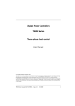
Figure 1-2 Example of an identification label for a 471 model thyristor unit
The information corresponds to nominal current 125 A,
nominal voltage 380 V, auxiliary supply in the range 350 to 450 V,
4-20 mA input, 'phase angle' firing with 'power' feedback, current limit
available, PLF alarm contact closed in alarm state, unit delivered with
no backplate.
The configuration labels present the factory settings.
The configuration labels present the factory settings.
The standard configuration (4-20 mA input, 'Phase angle' firing mode and frequency 50 Hz)
is shown on one of the configuration labels.
The standard configuration (4-20 mA input, 'Phase angle' firing mode and frequency 50 Hz)
is shown on one of the configuration labels.
If the configuration is different from the standard, it is shown in the appropriate boxes.
If the configuration is different from the standard, it is shown in the appropriate boxes.
In this case, the position of the configuration mini-switches for the selected input signal and
firing mode are shown.
In this case, the position of the configuration mini-switches for the selected input signal and
firing mode are shown.
The second configuration label shows the selection of the feedback mode using mini-switches.
The second configuration label shows the selection of the feedback mode using mini-switches.
The information on the configuration labels is shown in French and in English.
The information on the configuration labels is shown in French and in English.
Caution !
!
1-12
Caution !
!
Any reconfiguration done by the user will render obsolete
the original in-house configuration code shown on the label.
470 User Manual
1-12
Any reconfiguration done by the user will render obsolete
the original in-house configuration code shown on the label.
470 User Manual
Installation
Installation
Chapter 2
Chapter 2
INSTALLATION
INSTALLATION
Contents
page
Contents
Safety during installation ............................................... 2-2
Dimensions ................................................................... 2-3
Mechanical mounting .................................................... 2-4
470 User Manual
page
Safety during installation ............................................... 2-2
Dimensions ................................................................... 2-3
Mechanical mounting .................................................... 2-4
21-
470 User Manual
21-
Installation
Installation
Chapter 2 INSTALLATION
Chapter 2 INSTALLATION
SAFETY DURING INSTALLATION
SAFETY DURING INSTALLATION
Warning !
Warning !
470 units must be installed by a person authorised to work in an industrial low
voltage electrical environment.
470 units must be installed by a person authorised to work in an industrial low
voltage electrical environment.
Units must be installed in bulkhead mountings in fan-cooled electric cabinets,
guaranteeing the absence of condensation and pollution.
The cabinet must be closed and connected to the safety ground in accordance
with the standards NFC 15-100, IEC 364 or the current national standards.
Units must be installed in bulkhead mountings in fan-cooled electric cabinets,
guaranteeing the absence of condensation and pollution.
The cabinet must be closed and connected to the safety ground in accordance
with the standards NFC 15-100, IEC 364 or the current national standards.
For installations in fan-cooled cabinets, it is recommended to place a fan failure
detection device or a thermal safety control in the cabinet.
For installations in fan-cooled cabinets, it is recommended to place a fan failure
detection device or a thermal safety control in the cabinet.
The units must be mounted with the heatsink positioned vertically and with no
obstructions either above or below which could block the passage of the ventilation air.
The units must be mounted with the heatsink positioned vertically and with no
obstructions either above or below which could block the passage of the ventilation air.
If multiple units are installed in the same cabinet, they should be arranged in such a way
that the air from one unit cannot be admitted into the unit located above it.
If multiple units are installed in the same cabinet, they should be arranged in such a way
that the air from one unit cannot be admitted into the unit located above it.
Leave a vertical gap of at least 80 mm between two units.
Leave a gap of at least 20 mm between two units installed side by side.
Leave a vertical gap of at least 80 mm between two units.
Leave a gap of at least 20 mm between two units installed side by side.
The external thyristors controlled by a 472 driver unit must be at least 50 cm from the
472 unit.
The external thyristors controlled by a 472 driver unit must be at least 50 cm from the
472 unit.
Caution !
!
2-2
Caution !
!
The units are designed to be used at an ambient temperature less than or
equal to 50°C.
The units are designed to be used at an ambient temperature less than or
equal to 50°C.
Excessive overheating may cause incorrect operation of the unit, which in turn
may cause damage in the components.
Excessive overheating may cause incorrect operation of the unit, which in turn
may cause damage in the components.
471 series power thyristor units have permanent fan cooling.
471 series power thyristor units have permanent fan cooling.
470 User Manual
2-
470 User Manual
Installation
Installation
MECHANICAL MOUNTING
MECHANICAL MOUNTING
470 series units are plugged into a steel backplate located at the rear of the unit.
The backplate can be mounted:
• on a pair of asymmetric DIN rails
• on a vertical wall.
470 series units are plugged into a steel backplate located at the rear of the unit.
The backplate can be mounted:
• on a pair of asymmetric DIN rails
• on a vertical wall.
A
AA
AA
A
A
Backplate
Quarter turn
locking
53
15
Figure 2-2 Dimensions for attachment to a vertical wall (mm)
62
56
(47 for 472)
178
2 DIN
rails
50
105
20°
Rotation
pin
4 holes diam. 4.8
(2 holes for 472)
88 (470), 121 (471), 94(472)
Figure 2-2 Dimensions for attachment to a vertical wall (mm)
To mount the unit:
• tilt the unit forwards to approximately 20 degrees from the horizontal
• fit the rotation pin into the slot in the backplate
• raise the unit to the horizontal
• lock by a quarter of a turn.
To mount the unit:
• tilt the unit forwards to approximately 20 degrees from the horizontal
• fit the rotation pin into the slot in the backplate
• raise the unit to the horizontal
• lock by a quarter of a turn.
To dismount the unit:
• unlock the upper attachment by a quarter of a turn
• tilt the unit forwards to approximately 20 degrees from the horizontal
• free the unit from its backplate.
To dismount the unit:
• unlock the upper attachment by a quarter of a turn
• tilt the unit forwards to approximately 20 degrees from the horizontal
• free the unit from its backplate.
Warning !
Warning !
Before dismounting the unit, ensure that it is switched off and that
the heatsink is not hot.
Before dismounting the backplate, ensure that it is isolated from
the power supply.
Before dismounting the unit, ensure that it is switched off and that
the heatsink is not hot.
Before dismounting the backplate, ensure that it is isolated from
the power supply.
2-4
470 User Manual
24-
470 User Manual
Operation
Operation
Chapter 5
Chapter 5
OPERATION
OPERATION
Contents
page
Contents
Thyristor firing modes ............................................................ 5-2
General ............................................................................. 5-2
'Phase angle' mode .......................................................... 5-2
'Burst firing' mode ............................................................. 5-3
'Single cycle' mode ........................................................ 5-3
Modulation time ............................................................. 5-4
Soft start / end ............................................................... 5-5
Over-current elimination for the inductive load ................. 5-6
Control ................................................................................... 5-7
Control function ................................................................ 5-7
Pulse gating ...................................................................... 5-9
Power limit ........................................................................... 5-10
Current limit (optional) ......................................................... 5-11
Partial load failure detection ................................................ 5-12
Retransmission ................................................................... 5-13
Load current image ..................................................... 5-13
Load voltage image ..................................................... 5-13
True power image ....................................................... 5-13
Inhibit and safety quench .................................................... 5-14
470 User Manual
page
Thyristor firing modes ............................................................ 5-2
General ............................................................................. 5-2
'Phase angle' mode .......................................................... 5-2
'Burst firing' mode ............................................................. 5-3
'Single cycle' mode ........................................................ 5-3
Modulation time ............................................................. 5-4
Soft start / end ............................................................... 5-5
Over-current elimination for the inductive load ................. 5-6
Control ................................................................................... 5-7
Control function ................................................................ 5-7
Pulse gating ...................................................................... 5-9
Power limit ........................................................................... 5-10
Current limit (optional) ......................................................... 5-11
Partial load failure detection ................................................ 5-12
Retransmission ................................................................... 5-13
Load current image ..................................................... 5-13
Load voltage image ..................................................... 5-13
True power image ....................................................... 5-13
Inhibit and safety quench .................................................... 5-14
5-1
470 User Manual
5-1
Wiring
Wiring
Chapter 3
Chapter 3
WIRING
WIRING
Contents
page
Contents
Safety during wiring ..................................................................... 3-2
Fixing the power cables .............................................................. 3-3
User terminal blocks .................................................................... 3-5
Auxiliary power supply ........................................................ 3-6
Alarm relay contact ............................................................. 3-7
Load voltage information ..................................................... 3-8
Control cables ............................................................................. 3-9
Fixing ................................................................................... 3-9
Connecting the shield to the ground ................................... 3-10
Control terminal block ................................................................. 3-11
Driver terminal block ................................................................... 3-13
Input signals ................................................................................ 3-14
Safety quench ..................................................................... 3-14
Inhibit ................................................................................... 3-14
External control connection ................................................. 3-15
Control of multiple thyristor units .................................... 3-16
Parallel input connection ............................................ 3-16
Serial input connection ............................................... 3-16
Manual control connection .................................................. 3-17
Current limit connection (optional) ...................................... 3-18
Limit set using the potentiometer on the front panel ....... 3-18
Limit set using an external voltage ................................. 3-19
Limit set using an external potentiometer ......................... 3-20
Power limit connection ........................................................ 3-21
Limit set using the potentiometer on the front panel ....... 3-21
Limit set using an external potentiometer ......................... 3-22
Limit set using an external voltage ................................. 3-22
Retransmission signals ....................................................... 3-23
External thyristor block control (472 model) ........................ 3-24
Examples of wiring diagrams ...................................................... 3-26
470 and 471 model thyristor units ....................................... 3-26
Driver unit, 472 model ......................................................... 3-28
470 User Manual
page
Safety during wiring ..................................................................... 3-2
Fixing the power cables .............................................................. 3-3
User terminal blocks .................................................................... 3-5
Auxiliary power supply ........................................................ 3-6
Alarm relay contact ............................................................. 3-7
Load voltage information ..................................................... 3-8
Control cables ............................................................................. 3-9
Fixing ................................................................................... 3-9
Connecting the shield to the ground ................................... 3-10
Control terminal block ................................................................. 3-11
Driver terminal block ................................................................... 3-13
Input signals ................................................................................ 3-14
Safety quench ..................................................................... 3-14
Inhibit ................................................................................... 3-14
External control connection ................................................. 3-15
Control of multiple thyristor units .................................... 3-16
Parallel input connection ............................................ 3-16
Serial input connection ............................................... 3-16
Manual control connection .................................................. 3-17
Current limit connection (optional) ...................................... 3-18
Limit set using the potentiometer on the front panel ....... 3-18
Limit set using an external voltage ................................. 3-19
Limit set using an external potentiometer ......................... 3-20
Power limit connection ........................................................ 3-21
Limit set using the potentiometer on the front panel ....... 3-21
Limit set using an external potentiometer ......................... 3-22
Limit set using an external voltage ................................. 3-22
Retransmission signals ....................................................... 3-23
External thyristor block control (472 model) ........................ 3-24
Examples of wiring diagrams ...................................................... 3-26
470 and 471 model thyristor units ....................................... 3-26
Driver unit, 472 model ......................................................... 3-28
3-1
470 User Manual
3-1
Wiring
Wiring
Chapter 3
WIRING
Chapter 3
SAFETY DURING WIRING
SAFETY DURING WIRING
Warning !
Warning !
Wiring must be performed by personnel who are qualified to work with low voltage
electrical equipment. It is the user's responsibility to wire and protect the installation
in accordance with current professional standards.
A suitable device guaranteeing electrical separation of the equipment and the
power supply must be installed upstream from the unit in order to perform the
operation in complete safety.
All power and control connections are made to the terminal blocks located on the mounting
backplate and must be made without a unit present.
Warning !
Warning !
Before any connection or disconnection, make sure that the power and control cables
and wires are isolated from the voltage sources.
Before any connection or disconnection, make sure that the power and control cables
and wires are isolated from the voltage sources.
For safety reasons, the safety earth cable must be connected before any other
connection during wiring and must be the last cable to be disconnected.
For safety reasons, the safety earth cable must be connected before any other
connection during wiring and must be the last cable to be disconnected.
The safety earth is connected to the screw located on the strip provided for this purpose in the
lower part of the unit, behind the power terminals and labelled as follows:
The safety earth is connected to the screw located on the strip provided for this purpose in the
lower part of the unit, behind the power terminals and labelled as follows:
Caution !
!
Caution !
!
To ensure that the 470 unit is grounded correctly, make sure that it is attached to the
reference ground plane (panel or bulkhead). If this is not the case it is necessary to
add a ground connection no more than 10 cm long between the earth connection
and the reference ground plane.
Warning !
To ensure that the 470 unit is grounded correctly, make sure that it is attached to the
reference ground plane (panel or bulkhead). If this is not the case it is necessary to
add a ground connection no more than 10 cm long between the earth connection
and the reference ground plane.
Warning !
The purpose of this connection is to guarantee correct ground continuity. It is not,
in any circumstances, a substitute for the safety earth connection.
3-2
WIRING
470 User Manual
The purpose of this connection is to guarantee correct ground continuity. It is not,
in any circumstances, a substitute for the safety earth connection.
3-2
470 User Manual
Wiring
FIXING THE POWER CABLES
Wiring
FIXING THE POWER CABLES
The external wiring is performed at the front to the terminal blocks on the backplate, once the
backplate has been fixed, with the unit disconnected.
The external wiring is performed at the front to the terminal blocks on the backplate, once the
backplate has been fixed, with the unit disconnected.
For the 470 and 471 models, the power cables are attached to the power terminal blocks marked
For the 470 and 471 models, the power cables are attached to the power terminal blocks marked
'L' (Line) and ' ' (Load) located on the lower part of the unit.
'L' (Line) and ' ' (Load) located on the lower part of the unit.
The power and earth cables are connected to tunnel terminal blocks (470 model) or screw
terminals (471 model).
The power and earth cables are connected to tunnel terminal blocks (470 model) or screw
terminals (471 model).
Above 125 A, it is necessary to connect the power cables using round lugs.
Above 125 A, it is necessary to connect the power cables using round lugs.
The capacities of the power terminals are shown in table 3-1.
The capacities of the power terminals are shown in table 3-1.
The tightening torques must comply with the values shown in the same table.
The tightening torques must comply with the values shown in the same table.
Caution !
Tighten the power connections correctly.
Poor tightening can lead to incorrect operation of the thyristor
unit and can have serious consequences on the installation.
Caution !
Tighten the power connections correctly.
Poor tightening can lead to incorrect operation of the thyristor
unit and can have serious consequences on the installation.
!
Nominal current
15 A to 75 A
470 model
100 A to 150 A
471 model
472 model
Capacity of the power
and earth terminals
mm2
2.5 to 50
Power:
Earth:
!
Tightening torque
N.m
Nominal current
2.5
15 A to 75 A
470 model
50 or 70
25 to 50
10
2.5
100 A to 150 A
471 model
–
–
472 model
Table 3-1 Details of power wiring for the 470 series
Note:
Power:
Earth:
Tightening torque
N.m
2.5
50 or 70
25 to 50
10
2.5
–
–
Table 3-1 Details of power wiring for the 470 series
Since the 472 units are electronic driver units, they do not contain power terminal blocks.
470 User Manual
Capacity of the power
and earth terminals
mm2
2.5 to 50
3-3
Note:
Since the 472 units are electronic driver units, they do not contain power terminal blocks.
470 User Manual
3-3
Wiring
Wiring
AAA
AAA
AAA
AAA
AAA
AAA
AAA
AAA
AAA
AA
AA
15
Backplate
16
Load
Safety earth
Fixing
36
L
Line
470 model
AA
AA
1 mm
bare cable
471 model
AA
AA
AA
AA
The cross-section of the connecting conductors used must comply with the IEC 943 standard.
Distance between terminals
mm
Model
Fixing
Distance between terminals
mm
470
35 mm2 tunnel terminal
55
470
35 mm2 tunnel terminal
55
471
M10 Screw
61.5
471
M10 Screw
61.5
Table 3-2 Power wiring details for the 470 series
3-4
35
Figure 3-1 Power and safety earth cable fixing points
The cross-section of the connecting conductors used must comply with the IEC 943 standard.
Model
Without terminal covers:
Terminal cover
Terminal cover
Figure 3-1 Power and safety earth cable fixing points
AAA
AAA
AAA
AAA
AAA
AAA
AAA
AAA
AA
AAA
AA
Table 3-2 Power wiring details for the 470 series
470 User Manual
3-4
470 User Manual
Wiring
USER TERMINAL BLOCKS
Wiring
USER TERMINAL BLOCKS
The user terminal blocks are located at the top left of the backplate.
They are used to connect:
• the auxiliary power supply,
• the PLF alarm relay contact,
• the load voltage (for control).
The user terminal blocks are located at the top left of the backplate.
They are used to connect:
• the auxiliary power supply,
• the PLF alarm relay contact,
• the load voltage (for control).
The unit must be unplugged from the backplate in order to access the user terminal blocks.
The connections are made using screw terminal blocks; terminal tightening torque: 0,7 N.m.
The maximum wire cross-section is 2.5 mm2.
The unit must be unplugged from the backplate in order to access the user terminal blocks.
The connections are made using screw terminal blocks; terminal tightening torque: 0,7 N.m.
The maximum wire cross-section is 2.5 mm2.
470 and
471 models
PLF
41
N
N / L2
53
61
63
21
2
22
PLF
41
42
N
230V
AUTRE
51
52
53
1
21
2
22
3
23
4
24
5
25
6
26
7
8
470 User Manual
AAA
AAA
AUTRE
52
1
472
model
Figure 3-2 User terminal blocks
230V
51
42
AAA
N / L2
61
63
27
28
Figure 3-2 User terminal blocks
3-5
470 User Manual
3-5
Wiring
Wiring
Auxiliary power supply
Auxiliary power supply
The auxiliary power supply powers the following:
The auxiliary power supply powers the following:
• the electronic control
• the fan (for fan-cooled units)
• the partial load failure detection circuit.
• the electronic control
• the fan (for fan-cooled units)
• the partial load failure detection circuit.
Terminals 51 and 52 are used when the electronic control circuit is powered at 230 V (in the
voltage range 200 V to 260 V).
Terminals 51 and 52 are used when the electronic control circuit is powered at 230 V (in the
voltage range 200 V to 260 V).
Terminals 51 and 53 are used for voltages outside the range 200-260 V (110 or 400 V,
for example).
Terminals 51 and 53 are used for voltages outside the range 200-260 V (110 or 400 V,
for example).
Terminal 51 is the reference phase or neutral.
Terminal 51 is the reference phase or neutral.
The auxiliary power supply voltage is specified in the unit code (see page 1-9).
The auxiliary power supply voltage is specified in the unit code (see page 1-9).
Caution !
!
Caution !
!
• The phases arriving on terminals 51 to 53 must be identical to those on the
unit's power terminals, especially if several units are distributed amongst
several phases of a three-phase power supply.
• The order of connection must be observed.
• The order of connection must be observed.
• The control must be powered up after or at the same time as the power.
• The control must be powered up after or at the same time as the power.
• The control must be powered down before or at the same time as the power.
• The control must be powered down before or at the same time as the power.
The auxiliary power supply is protected from the electrical disturbances on the power supply
in common mode.
The auxiliary power supply is protected from the electrical disturbances on the power supply
in common mode.
Caution !
!
3-6
• The phases arriving on terminals 51 to 53 must be identical to those on the
unit's power terminals, especially if several units are distributed amongst
several phases of a three-phase power supply.
Caution !
!
• Each connection wire from the auxiliary power supply to a
phase must be protected by a 1 A fuse.
470 User Manual
3-6
• Each connection wire from the auxiliary power supply to a
phase must be protected by a 1 A fuse.
470 User Manual
Wiring
Alarm relay contact
Wiring
Alarm relay contact
The connection of the partial load failure detection relay contact (PLF alarm) which signals the
active alarm state is made on the user terminal block located in the upper part of the thyristor
unit, on the left.
The connection of the partial load failure detection relay contact (PLF alarm) which signals the
active alarm state is made on the user terminal block located in the upper part of the thyristor
unit, on the left.
The contact output terminals are marked 41 and 42 on the terminal block label.
The contact output terminals are marked 41 and 42 on the terminal block label.
The PLF alarm relay is de-energised in the alarm state (and when the unit is switched off).
The PLF alarm relay is de-energised in the alarm state (and when the unit is switched off).
On standard models, the relay contact available between terminals 41 and 42 is open in the
alarm state and in the event of a power failure.
On standard models, the relay contact available between terminals 41 and 42 is open in the
alarm state and in the event of a power failure.
Optionally (code 83), the alarm relay contact is closed in the alarm state.
Optionally (code 83), the alarm relay contact is closed in the alarm state.
The partial load failure detection relay contact is protected against disturbances by an RC
snubber circuit on the control board.
The partial load failure detection relay contact is protected against disturbances by an RC
snubber circuit on the control board.
The alarm contact cutoff capacity is 0.25 A under 250 Vac or 30 Vdc.
The contact cutoff voltage must not exceed 250 Vac in any circumstances.
The alarm contact cutoff capacity is 0.25 A under 250 Vac or 30 Vdc.
The contact cutoff voltage must not exceed 250 Vac in any circumstances.
The PLF alarm relay contact output is suitable for driving an alarm unit.
The PLF alarm relay contact output is suitable for driving an alarm unit.
The PLF alarm relay is acknowledged either by switching off the thyristor unit or by a return to
the nominal current.
The PLF alarm relay is acknowledged either by switching off the thyristor unit or by a return to
the nominal current.
470 User Manual
3-7
470 User Manual
3-7
Wiring
Wiring
Load voltage information
Load voltage information
The 470 series power units and driver units use the load voltage information to perform
true power control.
The load voltage measurement is connected to terminals 61 and 63 on the user terminal block.
The 470 series power units and driver units use the load voltage information to perform
true power control.
The load voltage measurement is connected to terminals 61 and 63 on the user terminal block.
Terminal 61 must be connected to the 'Load' - 'Neutral or Line 2' common point.
Terminal 61 must be connected to the 'Load' - 'Neutral or Phase 2' common point.
Terminal 63 must be connected to the 'Load' - ' terminal or external thyristor' common point.
Terminal 63 must be connected to the 'Load' - ' terminal or external thyristor' common point.
!
Caution !
The order of connection must be observed, otherwise, the
power measured could be negative and cause the control
to malfunction.
!
Caution !
The order of connection must be observed, otherwise, the
power measured could be negative and cause the control
to malfunction.
LOAD
To Neutral
or Line 2
1 A fuses
PLF
1
41
42
230V
AUTRE
N/L2
51
52
53
61
3-8
63
21
2
22
3
23
AAAA
AAAA
AAAA
AAAA
AAAA
AAAA
AAAA
AAAA
AAAA
AAAA
AAAA
AAA
AAA
Figure 3-3 Load voltage connection (example for 470 and 471 models)
AA
AA
AA
N
AAAAA
AAAAA
AAAAA
AAAAA
AAAAA
AAAAA
AAAAA
AAAAA
AAAAA
AAAAA
AAA
AAA
L
To Line 1
Figure 3-3 Load voltage connection (example for 470 and 471 models)
470 User Manual
3-8
470 User Manual
Wiring
CONTROL CABLES
Wiring
CONTROL CABLES
Caution !
Caution !
The control connections must be made with shielded cables connected to earth at both
ends in order to ensure satisfactory immunity against interference.
!
The control connections must be made with shielded cables connected to earth at both
ends in order to ensure satisfactory immunity against interference.
!
Separate the control cables from the power cables in the cable trays.
Separate the control cables from the power cables in the cable trays.
Fixing
Fixing
The control wires must be grouped together in a shielded cable passing through the cable
clamp under the unit, to the left of the power terminal block.
The control wires must be grouped together in a shielded cable passing through the cable
clamp under the unit, to the left of the power terminal block.
AAA
AAA
AAA
AAAA
AAAA
AAAA
15
16
35
Backplate
36
Cable tightening
screw with
shield
Stirrup
Control cable
clamp (seen from
below)
Figure 3-4 Control cable clamp location
Control cable
clamp
AA
AAAA
AAAA
Driver cable
clamp
Figure 3-4 Control cable clamp location
Important !
To facilitate the earthing of the cable shield and to ensure maximum
immunity against electromagnetic interference, the metal cable clamp is
fixed directly to the ground of the unit.
470 User Manual
AA
AA AA
AA AA
L
Important !
To facilitate the earthing of the cable shield and to ensure maximum
immunity against electromagnetic interference, the metal cable clamp is
fixed directly to the ground of the unit.
3-9
470 User Manual
3-9
Wiring
Wiring
Connecting the shield to the ground
Connecting the shield to the ground
To insert the control cable and ground its shield:
• Strip the shielded cable as shown in figure 3-5,a.
The control wires must be long enough for the connection between the metal cable clamp
and the control terminal block. The wiring inside the unit must be as short as possible.
To insert the control cable and ground its shield:
• Strip the shielded cable as shown in figure 3-5,a.
The control wires must be long enough for the connection between the metal cable clamp
and the control terminal block. The wiring inside the unit must be as short as possible.
Control wires
AAA
AAA
AAA
AAA
AAA
Shield
Isolating sheath
1.5 to 2 cm
a)
20 to 40 cm
Control wires
Isolating sheath
Shield folded back
Figure 3-5 Control cable stripping
b)
Figure 3-5 Control cable stripping
• Fold back the shield on the isolating sheath (figure 3-4,b).
• Insert the cable in the metal cable clamp so that the shield is located in the stirrup and does not
pass the cable clamp.
• Tighten the stirrup (3.5 x 1 flat screwdriver; tightening: 0.7 N.m.).
• Fold back the shield on the isolating sheath (figure 3-4,b).
• Insert the cable in the metal cable clamp so that the shield is located in the stirrup and does not
pass the cable clamp.
• Tighten the stirrup (3.5 x 1 flat screwdriver; tightening: 0.7 N.m.).
AA
AA
AA
AA
AAAA
AAAAAAAA
AA
AAAAAA
AAAA
Wires
Backplate
Cable clamp
Tightening screw
Shield folded back
Cable
Left-hand side view
Figure 3-6 Cable tightening and shield grounding
Figure 3-6 Cable tightening and shield grounding
The possible diameter of the cables with the shield folded back is 5 to 10 mm per cable clamp.
3-10
470 User Manual
The possible diameter of the cables with the shield folded back is 5 to 10 mm per cable clamp.
3-10
470 User Manual
Wiring
CONTROL TERMINAL BLOCK
Wiring
CONTROL TERMINAL BLOCK
The following connections are made on the control board user terminal block:
The following connections are made on the control board user terminal block:
• the (external or manual) input signal
• the thyristor unit operation inhibit
• the threshold current limit
• the load current retransmission.
The control terminal block is fixed on the backplate and can be accessed after the 470 thyristor
unit has been unplugged.
• the (external or manual) input signal
• the thyristor unit operation inhibit
• the threshold current limit
• the load current retransmission.
The control terminal block is fixed on the backplate and can be accessed after the 470 thyristor
unit has been unplugged.
Warning !
Warning !
Dangerous live parts may be accessible when the unit is unplugged.
Dangerous live parts may be accessible when the unit is unplugged.
1
21
22
23
24
Control terminal block
2
3
4
9
10
11
12
13
14
15
16
Control
cable clamp
Figure 3-7 470 thyristor unit control and driver terminal labelling
2
Backplate
26
27
28
29
30
31
32
33
34
35
36
L
Driver
cable clamp
Figure 3-7 470 thyristor unit control and driver terminal labelling
2
Control terminal block capacity: 0.5 mm2 to 2.5 mm2.
Control terminal tightening:
0.7 N.m.
Control terminal block capacity: 0.5 mm to 2.5 mm .
Control terminal tightening:
0.7 N.m.
470 User Manual
25
5
6
7
8
AAA
AAA
AAA
AAA
AAA
AAA
AAA
AAA
AAA
AAA
AAA
AAA
AAA
AAA
AAA
AAA
A
A
A
Driver terminal block
AAA
AAA
AAA
AAA
AAA
AAA
AAA
AAA
AAA
AAA
AAA
AAA
AAA
AAA
AAA
AAAA
A
A
3-11
470 User Manual
3-11
Wiring
Wiring
Terminal number
1
Assignment
Terminal number
Not connected
1
2
3
Not connected
2
Load current image output
3
Retransmission 0-2.5 V
Load current image output
Retransmission 0-2.5 V
Full wave rectified signal
Full wave rectified signal
4
Manual input
4
Manual input
5
External input
5
External input
6
Common 0 V
6
Common 0 V
7
Not connected
7
Not connected
8
8
9
9
10
10
11
3-12
Assignment
11
12
+10 V user voltage
12
+10 V user voltage
13
Not used
13
Not used
14
Current limit input
14
Current limit input
15
Not used
15
Not used
16
Thyristor unit operation
16
Thyristor unit operation
inhibit input
inhibit input
Table 3-3 Control terminal identification
Table 3-3 Control terminal identification
470 User Manual
3-12
470 User Manual
Wiring
DRIVER TERMINAL BLOCK
Wiring
DRIVER TERMINAL BLOCK
The following connections are made on the driver board user terminal block:
The following connections are made on the driver board user terminal block:
• the safety quench connection
• the load voltage signal
• the power limit signal
• the retransmission signals.
• the safety quench connection
• the load voltage signal
• the power limit signal
• the retransmission signals.
On the 472 model only, the external thyristor firing signals and the current information are also
connected to the driver terminal block.
The driver terminal block is fixed on the backplate and can be accessed after the 470 thyristor
unit has been unplugged (see figure 3-7).
On the 472 model only, the external thyristor firing signals and the current information are also
connected to the driver terminal block.
The driver terminal block is fixed on the backplate and can be accessed after the 470 thyristor
unit has been unplugged (see figure 3-7).
Warning !
Warning !
Dangerous live parts may be accessible when the unit is unplugged.
Dangerous live parts may be accessible when the unit is unplugged.
Control terminal block capacity:
Control terminal tightening:
Terminal number
21 and 22
23 (for 472)
24 (for 472)
25
26 (for 472)
27 (for 472)
28 to 32
33
34
35
36
37 and 38 (for 472)
0.5 mm2 to 2.5 mm2.
0.7 N.m.
Control terminal block capacity:
Control terminal tightening:
Assignment
Terminal number
Safety quench
External thyristor 1 cathode
External thyristor 1 gate
Not used
External thyristor 2 cathode
External thyristor 2 gate
Not connected
0 - 2.5 Vac load voltage image output
0 - 2.5 Vac load current image output
Controlled parameter limit input
0 - 10 Vdc controlled parameter retransmission
External thyristor load current signal input
21 and 22
23 (for 472)
24 (for 472)
25
26 (for 472)
27 (for 472)
28 to 32
33
34
35
36
37 and 38 (for 472)
Table 3-4 Terminal identification on the driver board terminal block
0.5 mm2 to 2.5 mm2.
0.7 N.m.
Assignment
Safety quench
External thyristor 1 cathode
External thyristor 1 gate
Not used
External thyristor 2 cathode
External thyristor 2 gate
Not connected
0 - 2.5 Vac load voltage image output
0 - 2.5 Vac load current image output
Controlled parameter limit input
0 - 10 Vdc controlled parameter retransmission
External thyristor load current signal input
Table 3-4 Terminal identification on the driver board terminal block
For the 470 and 471 models, the terminal numbers on the driver terminal block are 21 to 36.
For the 470 and 471 models, the terminal numbers on the driver terminal block are 21 to 36.
For the 472 model, the terminal numbers on the driver terminal block are 21 to 40.
For the 472 model, the terminal numbers on the driver terminal block are 21 to 40.
470 User Manual
3-13
470 User Manual
3-13
Wiring
Wiring
INPUT SIGNALS
INPUT SIGNALS
The control wires are connected to the screw terminals on the control terminal block attached to the
backplate. The control terminal block is accessible with the thyristor unit dismounted from the backplate.
The control wires are connected to the screw terminals on the control terminal block attached to the
backplate. The control terminal block is accessible with the thyristor unit dismounted from the backplate.
To dismount the thyristor unit from its backplate:
• unlock the upper attachment by a quarter of a turn
• tilt the unit forwards to approximately 20 degrees from the horizontal
• free the unit from its backplate.
To dismount the thyristor unit from its backplate:
• unlock the upper attachment by a quarter of a turn
• tilt the unit forwards to approximately 20 degrees from the horizontal
• free the unit from its backplate.
Warning !
Warning !
• Before dismounting the unit, ensure that the heatsink is not hot.
• Dangerous live parts may be accessible if the unit is dismounted when the thyristor
unit is switched on.
• Before dismounting the unit, ensure that the heatsink is not hot.
• Dangerous live parts may be accessible if the unit is dismounted when the thyristor
unit is switched on.
The thyristor units can be controlled by an external analogue signal (from a controller or
another signal source) or manually by an external potentiometer connected to the control
terminal block.
The thyristor units can be controlled by an external analogue signal (from a controller or
another signal source) or manually by an external potentiometer connected to the control
terminal block.
Important !
Important !
The control inputs are isolated by transformers from the auxiliary supply voltage and
from the power section.
Safety quench
Safety quench
If the unit is unplugged from its backplate, the operation of the thyristor unit is stopped.
If the unit is unplugged from its backplate, the operation of the thyristor unit is stopped.
Terminals 21 and 22 on the driver terminal block (which must be connected together) are the
first two terminals to be disconnected from the backplate, which instantly (10 ms maximum)
causes the thyristor unit output power to be reset.
Terminals 21 and 22 on the driver terminal block (which must be connected together) are the
first two terminals to be disconnected from the backplate, which instantly (10 ms maximum)
causes the thyristor unit output power to be reset.
Inhibit
3-14
The control inputs are isolated by transformers from the auxiliary supply voltage and
from the power section.
Inhibit
Inhibit indicates that thyristor firing is not possible irrespective of the control signal. The
inhibit is effective when a DC voltage is set on terminal 16.
The inhibit voltage must be between 4 V and 32 V with reference to terminal 6 ('0 V').
Inhibit indicates that thyristor firing is not possible irrespective of the control signal. The
inhibit is effective when a DC voltage is set on terminal 16.
The inhibit voltage must be between 4 V and 32 V with reference to terminal 6 ('0 V').
Firing can be inhibited by connecting terminal 16 to terminal 12 ('+10 V') on the same control
terminal block. To deactivate the inhibit, simply do not connect terminal 16 or set it to a DC
voltage between -2 V and 1 V.
Firing can be inhibited by connecting terminal 16 to terminal 12 ('+10 V') on the same control
terminal block. To deactivate the inhibit, simply do not connect terminal 16 or set it to a DC
voltage between -2 V and 1 V.
470 User Manual
3-14
470 User Manual
Wiring
External control connection
Wiring
External control connection
External
control
signal
AAA
AAA
AAA
AAA
AAA
AAA
AAA
AAA
AAA
AAA
AAA
AAA
AAA
AAA
AAA
6
+10 V
12
14
Inhibit
16
Enable
Backplate
35
Figure 3-8 External control signal connection
For normal operation of the 470 series thyristor unit with the external control:
For normal operation of the 470 series thyristor unit with the external control:
• disconnect the 'Inhibit' input (terminal 16) from the '+10 V' voltage (terminal 12)
• terminal 14 ('Current limit' option) should be connected to terminal 12 ('+10 V')
• the 'Manual input" (terminal 4) should be connected to terminal 6 ('0 V')
• the 'Power limit' input (terminal 35) should be connected to terminal 12 ('+10 V')
• short-circuit terminals 21 and 22 ('Safety quench').
470 User Manual
22
5
0V
Figure 3-8 External control signal connection
21
4
+
AAA
AAA
AAA
AAA
AAA
AAA
AAA
AAA
AAA
AAA
AAA
AAA
AAA
AAA
AAA
Safety quench
The external signal is applied to terminals 5 and 6 of the control terminal block ('+' on
terminal 5).
100% power limit
The external signal is applied to terminals 5 and 6 of the control terminal block ('+' on
terminal 5).
• disconnect the 'Inhibit' input (terminal 16) from the '+10 V' voltage (terminal 12)
• terminal 14 ('Current limit' option) should be connected to terminal 12 ('+10 V')
• the 'Manual input" (terminal 4) should be connected to terminal 6 ('0 V')
• the 'Power limit' input (terminal 35) should be connected to terminal 12 ('+10 V')
• short-circuit terminals 21 and 22 ('Safety quench').
3-15
470 User Manual
3-15
Wiring
Wiring
Control of multiple thyristor units
Control of multiple thyristor units
If multiple thyristor units are controlled by the same controller, the inputs can be connected in
parallel or in series.
All the thyristor units must be configured for the same thyristor firing mode and for the same
input signal.
Parallel input connection
If multiple thyristor units are controlled by the same controller, the inputs can be connected in
parallel or in series.
All the thyristor units must be configured for the same thyristor firing mode and for the same
input signal.
Parallel input connection
The inputs must be configured for voltage.
The input impedance for each thyristor unit is 50 kΩ.
The current required for each thyristor unit is 0.2 mA at full scale.
The inputs must be configured for voltage.
The input impedance for each thyristor unit is 50 kΩ.
The current required for each thyristor unit is 0.2 mA at full scale.
+
AA A AA
AA
A
AA
AA A AA
External
control
signal:
0-5 V
0-10 V
1-5 V
5
5
5
6
6
6
Unit
1
Unit
2
Unit
3
0V
Figure 3-9 Parallel input connection
Figure 3-9 Parallel input connection
Serial input connection
Serial input connection
The inputs must be configured for current.
The input impedance when configured for 0-10 mA or 0-5 mA is 1 kΩ.
For 0-20 mA and 4-20 mA inputs, the input impedance is 250 Ω .
At full scale, a voltage of 5 V is needed for each thyristor unit for the 0-20 mA and 4-20 mA
inputs (10 Vfor the 0-10 mA or 0-5 mA input).
+
External
control
signal:
AA
AA
AA
5
0-5 mA
0-10 mA
0-20 mA
4-20 mA
6
Unit
1
A
A
A
5
6
Unit
2
AA
AA
AA
5
6
Unit
3
0V
Figure 3-10 Serial input connection
3-16
Figure 3-10 Serial input connection
470 User Manual
3-16
470 User Manual
Wiring
Manual control connection
Wiring
Manual control connection
The 470 series unit can be controlled by an external potentiometer (manual control).
For manual control, the external potentiometer should be connected between terminals
6 ('0 V') and 12 ('+10 V'). The wiper is connected to terminal 4 ('Manual input').
The potentiometers used are from 4.5 kΩ to 10 kΩ.
For manual control, the 470 series unit should be configured for voltage.
For manual control, the 470 series unit should be configured for voltage.
21
22
4
100%
0%
5
6
Backplate
0V
4.7 k to 10 k
potentiometer
+10 V
12
14
Inhibit
16
Enable
Figure 3-11 470 thyristor unit manual input
If manual control is used, terminal 5 of the external input must be connected to '0 V'.
Caution !
Caution !
If the input signal is connected to terminal 5, the
two signals (external and manual) are added together.
!
The inhibit circuit should be open (terminal 16 is not connected to terminal 12).
Terminals 14 ('Current limit' option), 35 ('Power limit') and 12 ('+10 V') should be connected.
Terminals 21 and 22 ('Safety quench') should be connected.
470 User Manual
35
Figure 3-11 470 thyristor unit manual input
If manual control is used, terminal 5 of the external input must be connected to '0 V'.
!
AAA
AAA
AAA
AAA
AAA
AAA
AAA
AAA
AAA
AAA
AAA
AAA
AAA
AAA
AAA
100% power limit
AAAA
AAAA
AAAA
AAAA
AAAA
AAAA
AAAA
AAAA
AAAA
AAAA
AAAA
AAAA
AAAA
AAAA
AAAA
AAAA
Safety quench
The 470 series unit can be controlled by an external potentiometer (manual control).
For manual control, the external potentiometer should be connected between terminals
6 ('0 V') and 12 ('+10 V'). The wiper is connected to terminal 4 ('Manual input').
The potentiometers used are from 4.5 kΩ to 10 kΩ.
3-17
If the input signal is connected to terminal 5, the
two signals (external and manual) are added together.
The inhibit circuit should be open (terminal 16 is not connected to terminal 12).
Terminals 14 ('Current limit' option), 35 ('Power limit') and 12 ('+10 V') should be connected.
Terminals 21 and 22 ('Safety quench') should be connected.
470 User Manual
3-17
Wiring
Wiring
Current limit connection (optional)
Current limit connection (optional)
The 470 series thyristor units have the threshold current limit as an option.
The current limit is only available in the 'Phase angle' and 'Burst firing with soft start' firing modes.
The 470 series thyristor units have the threshold current limit as an option.
The current limit is only available in the 'Phase angle' and 'Burst firing with soft start' firing modes.
The threshold current limit is a function which is used to limit the load current to a specified
value, independently from the input signal.
The threshold current limit is a function which is used to limit the load current to a specified
value, independently from the input signal.
The current limit controls the squared RMS load current (I2).
The current limit controls the squared RMS load current (I2).
The current limit can be used with an external or manual control.
The current limit can be used with an external or manual control.
The current limit threshold can be set:
The current limit threshold can be set:
• by the potentiometer marked 'I limit / Limit. I' on the front panel,
• by an external voltage in cascade with the potentiometer on the front panel,
• by an external potentiometer in cascade with the potentiometer on the front panel.
Limit set using the potentiometer on the front panel
• by the potentiometer marked 'I limit / Limit. I' on the front panel,
• by an external voltage in cascade with the potentiometer on the front panel,
• by an external potentiometer in cascade with the potentiometer on the front panel.
Limit set using the potentiometer on the front panel
The 'I limit / Limit. I' potentiometer on the front panel is powered by the +10 V internal voltage
(terminal 14 on the control terminal block should be connected to terminal 12).
The 'I limit / Limit. I' potentiometer on the front panel is powered by the +10 V internal voltage
(terminal 14 on the control terminal block should be connected to terminal 12).
If the 'I limit / Limit. I' potentiometer is turned completely clockwise, the current value is
limited to 110% of the nominal thyristor unit current value.
If the 'I limit / Limit. I' potentiometer is turned completely clockwise, the current value is
limited to 110% of the nominal thyristor unit current value.
When this potentiometer is turned anti-clockwise, the maximum current falls to 0.
When this potentiometer is turned anti-clockwise, the maximum current falls to 0.
!
3-18
Caution !
If the adjustable limit is not used in the 'Current limit' option, it is nonetheless
necessary to connect terminals 14 and 12. Otherwise, the current limit is at zero
and the thyristor unit cannot output.
470 User Manual
!
3-18
Caution !
If the adjustable limit is not used in the 'Current limit' option, it is nonetheless
necessary to connect terminals 14 and 12. Otherwise, the current limit is at zero
and the thyristor unit cannot output.
470 User Manual
Wiring
Limit set using an external voltage
Wiring
Limit set using an external voltage
External
control
signal
AAA
AAA
AAA
AAA
AAA
AAA
AAA
AAA
AAA
AAA
AAA
AAA
AAA
AAA
AAA
21
22
4
+
5
6
0V
External current
limit voltage
+10 V
12
14
+
Inhibit
16
Enable
Figure 3-12 External voltage connection for the threshold current limit
AAAA
AAAA
AAAA
AAAA
AAAA
AAAA
AAAA
AAAA
AAAA
AAAA
AAAA
AAAA
AAAA
AAAA
AAAA
AAAA
Backplate
35
Safety quench
To set the current limit threshold using an external voltage, a 0-10 V voltage should be
connected between terminals 14 ('Current limit') and 6 ('0 V'), terminal 14 is positive.
100% power limit
To set the current limit threshold using an external voltage, a 0-10 V voltage should be
connected between terminals 14 ('Current limit') and 6 ('0 V'), terminal 14 is positive.
Figure 3-12 External voltage connection for the threshold current limit
When an external voltage is used to set the limit threshold, it reacts in cascade with the
position of the 'I limit / Limit. I' potentiometer on the front panel.
When an external voltage is used to set the limit threshold, it reacts in cascade with the
position of the 'I limit / Limit. I' potentiometer on the front panel.
This means that if the 'I limit / Limit. I' potentiometer is set, for example, to 50% current, the
external voltage from 0 V to 10 V limits the maximum current from 0% to 50% of the
nominal thyristor unit current.
This means that if the 'I limit / Limit. I' potentiometer is set, for example, to 50% current, the
external voltage from 0 V to 10 V limits the maximum current from 0% to 50% of the
nominal thyristor unit current.
The 'Current limit' (terminal 14) input impedance is greater than or equal to 150 kΩ..
The 'Current limit' (terminal 14) input impedance is greater than or equal to 150 kΩ..
470 User Manual
3-19
470 User Manual
3-19
Wiring
Wiring
Limit set using an external potentiometer
Limit set using an external potentiometer
For the threshold current limit, it is possible to use an external potentiometer.
A 10 kΩ potentiometer should be connected between terminals 6 ('0 V') and 12 ('+10 V') of
the control terminal block.
The potentiometer wiper should be connected to terminal 14 ('Current limit').
A 10 kΩ potentiometer should be connected between terminals 6 ('0 V') and 12 ('+10 V') of
the control terminal block.
The potentiometer wiper should be connected to terminal 14 ('Current limit').
AAAA
AAAA
AAAA
AAAA
AAAA
AAAA
AAAA
AAAA
AAAA
AAAA
AAAA
AAAA
AAAA
AAAA
AAAA
AAAA
21
22
4
+ External signal
5
6
0V
10 k
potentiometer
+10 V
12
Min.
current
Max.
current
14
Current limit
AAA
AAA
AAA
AAA
AAA
AAA
AAA
AAA
AAA
AAA
AAA
AAA
AAA
AAA
AAA
AAA
Backplate
Safety quench
For the threshold current limit, it is possible to use an external potentiometer.
35
Figure 3-13 External potentiometer connection for the threshold current limit
Figure 3-13 External potentiometer connection for the threshold current limit
The external potentiometer reacts in cascade with the 'I limit / Limit. I' potentiometer on
the front panel.
If the 'I limit / Limit. I' potentiometer is set, for example, to 70% current, the external
potentiometer can limit the maximum current from 0% to 70% of the nominal thyristor
unit current.
The external potentiometer reacts in cascade with the 'I limit / Limit. I' potentiometer on
the front panel.
If the 'I limit / Limit. I' potentiometer is set, for example, to 70% current, the external
potentiometer can limit the maximum current from 0% to 70% of the nominal thyristor
unit current.
3-20
470 User Manual
3-20
470 User Manual
Wiring
Power limit connection
Wiring
Power limit connection
The standard version of the 470 series thyristor units is equipped with the threshold limit of the
controlled parameter (power, squared current or squared load voltage).
The standard version of the 470 series thyristor units is equipped with the threshold limit of the
controlled parameter (power, squared current or squared load voltage).
This limit is a function which is used to limit the load current to a specified value,
independently from the setpoint.
This limit is a function which is used to limit the load current to a specified value,
independently from the setpoint.
The controlled parameter limit is called the 'Power limit' since, at a constant load resistance,
the parameters V2 and I2 are proportional to a dissipated power.
The controlled parameter limit is called the 'Power limit' since, at a constant load resistance,
the parameters V2 and I2 are proportional to a dissipated power.
If the current limit option is used and if the parameter I2 is selected for control, these two limits
(current and power) are redundant.
If the current limit option is used and if the parameter I2 is selected for control, these two limits
(current and power) are redundant.
The power limit threshold can be set in the following ways:
The power limit threshold can be set in the following ways:
• by the 'P.Limit' potentiometer on the front panel
• by an external voltage (in cascade with the 'P.Limit' potentiometer)
• by an external potentiometer (in cascade with the 'P.Limit' potentiometer).
• by the 'P.Limit' potentiometer on the front panel
• by an external voltage (in cascade with the 'P.Limit' potentiometer)
• by an external potentiometer (in cascade with the 'P.Limit' potentiometer).
Power limit set using the potentiometer on the front panel
Power limit set using the potentiometer on the front panel
For the load power threshold limit using the 'P.Limit' potentiometer, terminal 35 ('Power
limit input') on the driver terminal block should be connected to terminal 12 ('+ 10 V') on the
control terminal block.
For the load power threshold limit using the 'P.Limit' potentiometer, terminal 35 ('Power
limit input') on the driver terminal block should be connected to terminal 12 ('+ 10 V') on the
control terminal block.
The maximum power limit varies between 0% (when the 'P.Limit' potentiometer is turned
completely anti-clockwise) and 100% (when the potentiometer on the front panel is turned
completely clockwise).
The maximum power limit varies between 0% (when the 'P.Limit' potentiometer is turned
completely anti-clockwise) and 100% (when the potentiometer on the front panel is turned
completely clockwise).
470 User Manual
3-21
470 User Manual
3-21
Wiring
Wiring
Limit set using an external potentiometer
Limit set using an external potentiometer
The threshold power limit can be set using an external potentiometer.
A 10 kΩ external setting potentiometer should be connected between terminals 6 ('0 V') and
12 ('+10 V') on the control terminal block.
A 10 kΩ external setting potentiometer should be connected between terminals 6 ('0 V') and
12 ('+10 V') on the control terminal block.
The potentiometer wiper should be connected to terminal 35 ('Power limit input') on the driver
terminal block.
The potentiometer wiper should be connected to terminal 35 ('Power limit input') on the driver
terminal block.
AAA
AAA
AAA
AAA
AAA
AAA
AAA
AAA
AAA
AAA
AAA
AAA
AAA
AAA
AAA
21
22
4
+ External signal
5
6
0V
10 k
potentiometer
+10 V
12
min P
max P
14
Power
limit
Backplate
35
Figure 3-14 External potentiometer connection for the power limit
Figure 3-14 External potentiometer connection for the power limit
The power limit threshold setting (using an external potentiometer) reacts in cascade with the
'P. Limit' potentiometer on the front panel.
The power limit threshold setting (using an external potentiometer) reacts in cascade with the
'P. Limit' potentiometer on the front panel.
Setting using an external voltage
3-22
AAA
AAA
AAA
AAA
AAA
AAA
AAA
AAA
AAA
AAA
AAA
AAA
AAA
AAA
AAA
Safety quench
The threshold power limit can be set using an external potentiometer.
Setting using an external voltage
The power limit threshold setting external voltage reacts in cascade with the 'P. Limit'
potentiometer on the front panel.
The power limit threshold setting external voltage reacts in cascade with the 'P. Limit'
potentiometer on the front panel.
This voltage between 0 and 10 V should be connected between terminals 6 ('0 V') and 35
'Power limit input'. Terminal 35 is positive.
This voltage between 0 and 10 V should be connected between terminals 6 ('0 V') and 35
'Power limit input'. Terminal 35 is positive.
470 User Manual
3-22
470 User Manual
Wiring
Retransmission signals
Wiring
Retransmission signals
The current image is retransmitted in the form of a full wave rectified signal (2.5 V mean
between terminals 3 and 6 for the nominal load current) and in the form of an AC signal
(2.5 V RMS between terminals 34 and 6 in full firing).
The load voltage image is available between terminals 33 and 6 in the form of an AC voltage
(2.5 V RMS in full firing).
The load voltage image is available between terminals 33 and 6 in the form of an AC voltage
(2.5 V RMS in full firing).
The true power image (or squared load voltage or squared load current) in the form of a
DC voltage (10 V for a nominal calibrated load power) is available at terminal 36, referenced in
relation to 0 V (terminal 6).
The true power image (or squared load voltage or squared load current) in the form of a
DC voltage (10 V for a nominal calibrated load power) is available at terminal 36, referenced in
relation to 0 V (terminal 6).
The true power information is correct for the 'Phase angle' and 'Single cycle' firing modes; it is
modulated as a function of the modulation in 'Burst firing'.
The true power information is correct for the 'Phase angle' and 'Single cycle' firing modes; it is
modulated as a function of the modulation in 'Burst firing'.
The minimum impedance to be connected to the retransmission outputs is 5 kΩ.
The minimum impedance to be connected to the retransmission outputs is 5 kΩ.
21
22
3
4
5
6
0V
Backplate
+10 V
12
14
Figure 3-15 Retransmission signal connection
470 User Manual
Safety
quench
Load
parameter
images:
33
34
36
0V
+
Voltage 0-2.5Vac
+
AAA
AAA
AAA
AAA
AAA
AAA
AAA
AAA
AAA
AAA
AAA
AAA
AAA
AAA
AAA
AAA
Current 0-2.5Vac
+
AAA
AAA
AAA
AAA
AAA
AAA
AAA
AAA
AAA
AAA
AAA
AAA
AAA
AAA
AAA
AAA
Power
0-10Vdc
Control
Current
image
The current image is retransmitted in the form of a full wave rectified signal (2.5 V mean
between terminals 3 and 6 for the nominal load current) and in the form of an AC signal
(2.5 V RMS between terminals 34 and 6 in full firing).
Figure 3-15 Retransmission signal connection
3-23
470 User Manual
3-23
Wiring
Wiring
External thyristor block control (472 model)
External thyristor block control (472 model)
To control the external thyristor unit, the driver terminal block of the electronic driver unit
(472 model) is equipped with:
To control the external thyristor unit, the driver terminal block of the electronic driver unit
(472 model) is equipped with:
• thyristor firing signal outputs
• a load current measurement signal input.
• thyristor firing signal outputs
• a load current measurement signal input.
A load voltage measurement signal input is located on the user terminal block (see page 3-5).
A load voltage measurement signal input is located on the user terminal block (see page 3-5).
The thyristor firing signals are available on terminals 23, 24 and 26, 27.
The thyristor firing signals are available on terminals 23, 24 and 26, 27.
Terminals 23 and 24 should be connected to the cathode and gate, respectively, of the external
thyristor T1 (connected in the order 'Line-Load').
Terminals 23 and 24 should be connected to the cathode and gate, respectively, of the external
thyristor T1 (connected in the order 'Line-Load').
Terminals 26 and 27 should be connected to the cathode and gate, respectively, of the external
thyristor T2 (connected in the order 'Load-Line').
Terminals 26 and 27 should be connected to the cathode and gate, respectively, of the external
thyristor T2 (connected in the order 'Load-Line').
Caution !
Caution !
!
!
• Do not invert the 'Cathode-Gate' wires of thyristors T1 and T2
(a PLF alarm is activated since the thyristors cannot output)
(a PLF alarm is activated since the thyristors cannot output)
!
3-24
• Do not invert the 'Cathode-Gate' wires of thyristors T1 and T2
• The 472 driver unit should be at most 80 cm from the thyristor block.
Twist each pair of 'Cathode-Gate' wires.
• The twisted wires should not be placed near the power cables.
• The 472 driver unit should be at most 80 cm from the thyristor block.
Twist each pair of 'Cathode-Gate' wires.
• The twisted wires should not be placed near the power cables.
Terminals 38 and 39 are to be used for the secondary coil connection of the external current
transformer (nominal current 5 A) .
Terminals 38 and 39 are to be used for the secondary coil connection of the external current
transformer (nominal current 5 A) .
Warning !
Warning !
The current transformer should ensure dual isolation between the primary and
secondary coils. This isolation should be calculated with reference to the operating
voltage (thyristor block supply voltage).
The current transformer should ensure dual isolation between the primary and
secondary coils. This isolation should be calculated with reference to the operating
voltage (thyristor block supply voltage).
Caution !
!
The order of connection of the external current transformer must be observed.
Otherwise, the output power could be negative and induce a control malfunction.
The order of connection of the external current transformer must be observed.
Otherwise, the output power could be negative and induce a control malfunction.
470 User Manual
Caution !
3-24
470 User Manual
Wiring
Wiring
'Load voltage'
input
External
control
+
0V
AAA
AAA
AAA
AAA
AAA
AAA
AAA
AAA
AAA
AAA
AAA
AAA
AAA
AAA
AAA
3
4
5
6
+10 V
12
14
To
terminal
35
AAA
AAA
AAA
AAA
AAA
AAA
AAA
AAA
AAA
AAA
AAA
AAA
AAA
AAA
AAA
AAA
AAA
AAA
21
22
23
24
26
Safety
quench
T1 Cathode
To external
thyristor T1
T1 Gate
T2 Cathode
To external
thyristor T2
T2 Gate
27
Backplate
To +10V
35
S1
38
39
S2
To secondary coil of
external current
transformer
'Load current' input
Figure 3-16 External thyristor block control connection (472 model)
Figure 3-16 External thyristor block control connection (472 model)
For the full wiring diagram of the 472 driver unit, for power, the external thyristor block and
the external current transformer, see page 3-28.
For the full wiring diagram of the 472 driver unit, for power, the external thyristor block and
the external current transformer, see page 3-28.
470 User Manual
3-25
470 User Manual
3-25
Wiring
Wiring
EXAMPLES OF WIRING DIAGRAMS
EXAMPLES OF WIRING DIAGRAMS
The figures below give examples of full wiring diagrams for power, the auxiliary supply and
external control for the two 470 series model types:
The figures below give examples of full wiring diagrams for power, the auxiliary supply and
external control for the two 470 series model types:
• the 470 and 471 models with internal thyristors and incorporated measurement circuits
• the 472 model with an external thyristor block and external current transformer.
• the 470 and 471 models with internal thyristors and incorporated measurement circuits
• the 472 model with an external thyristor block and external current transformer.
The connection details for the power limit, current limit and different types of control are
explained in the previous paragraphs.
The connection details for the power limit, current limit and different types of control are
explained in the previous paragraphs.
For the specific features of the auxiliary power supply connection according to the power
supply voltage used, see page 3-6.
For the specific features of the auxiliary power supply connection according to the power
supply voltage used, see page 3-6.
470 and 471 model thyristor units
3-26
470 and 471 model thyristor units
The load current passes through the power terminals 'L' (Line) and ' ' (Load).
The load current passes through the power terminals 'L' (Line) and ' ' (Load).
The other end of the load is connected either to the neutral or to the second phase of the power
supply, depending on the selected configuration. The terminal 'L' should be connected to the
phase of the power supply (see figure 3-17).
The other end of the load is connected either to the neutral or to the second phase of the power
supply, depending on the selected configuration. The terminal 'L' should be connected to the
phase of the power supply (see figure 3-17).
470 User Manual
3-26
470 User Manual
Wiring
Wiring
Line
Line protection and
main circuit breaker
(user installation)
Load
Neutral
PLF relay
contact
1A fuses
41 42 51 52 53 61
63
21
22
External fuse for
150 A
External
control
signal
4
+
5
6
0V
470
or
471
+10 V
12
14
35
Control
cable
AAA
AAA
A
AAA
A
AA
AAA
AAA
AA
AAA
AA
Safety
earth
To
+10V
L
Figure 3-17 Example of 470 and 471 thyristor unit connection (Line-Neutral wiring)
Figure 3-17 Example of 470 and 471 thyristor unit connection (Line-Neutral wiring)
470 User Manual
AAA
AAA
A
AAA
A A
AAA
AAA
AAA
AAA
3-27
470 User Manual
3-27
Wiring
Wiring
Driver unit, 472 model
Driver unit, 472 model
The power section and the 472 driver unit are connected with thyristor firing signal connections
and the load current and voltage measurement circuits.
The power section and the 472 driver unit are connected with thyristor firing signal connections
and the load current and voltage measurement circuits.
L1
Line protection and
main circuit breaker
(user installation)
L2
PLF relay
contact
Load
1A fuses
High speed
fuse
41 42
Control
signal
21
22
23
3
4
+
1A fuse
51 52 53
T1 Cathode
T1 Gate
24
5
6
0V
T2 Cathode
26
61
63
27
472
+10 V
External
thyristor
block
12
To +10V
35
To
terminal
35
S1
'Load
current'
input
38
39
Figure 3-18 Example of 472 driver unit connection (line-to-line wiring)
3-28
470 User Manual
T1
Plug-in
socket
14
Control
cable
T2
T2 Gate
A
A
AA
AA
S2
P1
P2
External current
transformer
Driver
cable
Safety
earth
Figure 3-18 Example of 472 driver unit connection (line-to-line wiring)
3-28
470 User Manual
Configuration
Configuration
Chapter 4
Chapter 4
CONFIGURATION
CONFIGURATION
Contents
page
Contents
Safety during configuration ................................................... 4-2
Location of the configuration equipment ............................... 4-3
Configuration of the control board ......................................... 4-6
Input type ........................................................................... 4-6
Automatic input (external signal) .................................... 4-6
Manual input ................................................................... 4-6
Thyristor firing mode .......................................................... 4-7
Frequency .......................................................................... 4-7
Configuration of the driver board ........................................... 4-8
470 User Manual
page
Safety during configuration ................................................... 4-2
Location of the configuration equipment ............................... 4-3
Configuration of the control board ......................................... 4-6
Input type ........................................................................... 4-6
Automatic input (external signal) .................................... 4-6
Manual input ................................................................... 4-6
Thyristor firing mode .......................................................... 4-7
Frequency .......................................................................... 4-7
Configuration of the driver board ........................................... 4-8
41-
470 User Manual
41-
Configuration
Configuration
Chapter 4 CONFIGURATION
Chapter 4 CONFIGURATION
SAFETY DURING CONFIGURATION
SAFETY DURING CONFIGURATION
The thyristor unit is configured using mini-switches and mobile jumpers located on the
control board.
The thyristor unit is configured using mini-switches and mobile jumpers located on the
control board.
!
Important !
The unit is supplied fully configured in accordance
with the code on the identification label.
!
This chapter is included in order to
This chapter is included in order to
• check that the configuration is compatible with the application, or
• modify, if necessary, certain characteristics of the thyristor unit on-site.
• check that the configuration is compatible with the application, or
• modify, if necessary, certain characteristics of the thyristor unit on-site.
Warning !
4-2
Important !
The unit is supplied fully configured in accordance
with the code on the identification label.
Warning !
For safety reasons, the reconfiguration of the thyristor unit using jumpers
must be performed with the unit switched off by qualified personnel.
For safety reasons, the reconfiguration of the thyristor unit using jumpers
must be performed with the unit switched off by qualified personnel.
Before starting the reconfiguration procedure, check that the thyristor unit
is isolated and that an occasional power-up is impossible.
Before starting the reconfiguration procedure, check that the thyristor unit
is isolated and that an occasional power-up is impossible.
After the reconfiguration of the unit, correct the codes on the identification
label to prevent any maintenance problems later.
After the reconfiguration of the unit, correct the codes on the identification
label to prevent any maintenance problems later.
470 User Manual
4-2
470 User Manual
Configuration
Configuration
LOCATION OF THE CONFIGURATION EQUIPMENT
LOCATION OF THE CONFIGURATION EQUIPMENT
The jumpers and configuration mini-switch strips are located on the thyristor unit control and
driver boards.
The jumpers and configuration mini-switch strips are located on the thyristor unit control and
driver boards.
The configuration mini-switches can be accessed at the rear of the unit when it is unplugged
from its backplate. Their positions can be changed using a 0.4 x 2.5 mm flat screwdriver.
The configuration mini-switches can be accessed at the rear of the unit when it is unplugged
from its backplate. Their positions can be changed using a 0.4 x 2.5 mm flat screwdriver.
Input and firing mode
configuration miniswitches
Driver board
AAAAAA
AAAAAA
AA
AA
AA
AA
AA
AA
AA
AA
AA
AA
AA
AA
AA
AA
Setting
potentiometer
Fuse
AA
AA
AA
AA
AA
AA
AA
AA
AA
AA
AA
AA
AA
AA
Control board
Control
configuration
mini-switches
Figure 4-1 Rear view of the 470 series thyristor unit (without backplate)
470 User Manual
Figure 4-1 Rear view of the 470 series thyristor unit (without backplate)
43-
470 User Manual
43-
Configuration
Configuration
Two strips of mini-switches are used to configure:
•
•
•
•
Two strips of mini-switches are used to configure:
•
•
•
•
the input type and the control signal level
the thyristor firing mode
the frequency of the power supply used
the controlled parameter (feedback)
the input type and the control signal level
the thyristor firing mode
the frequency of the power supply used
the controlled parameter (feedback)
A AA
AA
AAA
AA
AA
A
AA AA
AAAAA
AA
AAA
A
AA
A
AAA A
Input and firing mode
configuration mini-switches
Control
configuration miniswitches
4 5 6 7 8 ON
SW 1
8
7
6
5
SW
ON
1 2 3 4
13
14
15
16
1
3
2
1
2
3
4
Control board
Driver board
Figure 4-2 Mini-switch strips
4-4
Figure 4-2 Mini-switch strips
In the configuration tables below, the switches of the mini-switches are indicated as follows:
In the configuration tables below, the switches of the mini-switches are indicated as follows:
1 - switch lowered towards the board (ON position)
0 - switch raised.
1 - switch lowered towards the board (ON position)
0 - switch raised.
470 User Manual
4-4
470 User Manual
Configuration
Configuration
Two configuration jumpers J1 and J2 are located on the control board.
Two configuration jumpers J1 and J2 are located on the control board.
They are used to configure:
They are used to configure:
• soft start / end
• the Burst firing mode (fast cycle or slow cycle)
• soft start / end
• the Burst firing mode (fast cycle or slow cycle)
Configuration
mini-switches
Configuration jumpers
Setting potentiometer
P4
PLF
detection:
Indicator
light
0
LED
REL
J2
1
P4
Setting
Test
button
SW1
0
Front panel
1
Figure 4-3 Location of configuration equipment on the control board.
Current
limit setting
(optional)
TR1
Diagnostic
socket (Left)
Figure 4-3 Location of configuration equipment on the control board.
Thyristor units ordered with a short code are supplied with the following configuration:
Thyristor units ordered with a short code are supplied with the following configuration:
• the input configured for 4-20 mA
• the thyristor firing mode: firing angle variation (Phase angle)
• frequency 50 Hz
• the thyristor delayed firing potentiometer set to the maximum start ramp (resistive load)
and to 90° delayed firing (inductive and transformer connected load).
• the input configured for 4-20 mA
• the thyristor firing mode: firing angle variation (Phase angle)
• frequency 50 Hz
• the thyristor delayed firing potentiometer set to the maximum start ramp (resistive load)
and to 90° delayed firing (inductive and transformer connected load).
470 User Manual
J1
8
7
6
5
4
3
2
1
45-
470 User Manual
45-
Configuration
Configuration
CONFIGURATION OF THE CONTROL BOARD
CONFIGURATION OF THE CONTROL BOARD
Input type
Input type
The input signal type is configured using mini-switches 1 to 4 (strip SW1).
Reconfiguration is possible when the thyristor unit is disconnected from its backplate.
The input signal type is configured using mini-switches 1 to 4 (strip SW1).
Reconfiguration is possible when the thyristor unit is disconnected from its backplate.
In tables 4-1 to 4-4, the 1 indicates the lowered position of the switch (towards the board).
In tables 4-1 to 4-4, the 1 indicates the lowered position of the switch (towards the board).
Automatic input (external signal)
Automatic input (external signal)
Automatic
external
input signal
Position of the mini-switches SW1
1
2
3
0-5 V
0-10 V
1-5 V
0-5 mA
0-10 mA
1-5 mA
0-20 mA
4-20 mA
0
1
0
0
1
0
0
0
0
0
1
0
0
1
0
1
0
0
0
1
1
1
1
1
4
Automatic
external
input signal
1
2
3
4
0
0
0
0
0
0
1
1
0-5 V
0-10 V
1-5 V
0-5 mA
0-10 mA
1-5 mA
0-20 mA
4-20 mA
0
1
0
0
1
0
0
0
0
0
1
0
0
1
0
1
0
0
0
1
1
1
1
1
0
0
0
0
0
0
1
1
Table 4-1 Configuration of the automatic input
Table 4-1 Configuration of the automatic input
Manual input
Manual input
The manual input voltage range (external potentiometer wiper at terminal 4) depends on the
configuration of the automatic input. Table 4-2 gives the manual input voltage range as a
function of the limit positions of the potentiometer.
Position of mini-switches
1
2
0
1
0
0
0
1
The manual input voltage range (external potentiometer wiper at terminal 4) depends on the
configuration of the automatic input. Table 4-2 gives the manual input voltage range as a
function of the limit positions of the potentiometer.
Voltage range at
manual input
Position of mini-switches
0-5 V
0-10 V
1.25 V - 6.25 V
Table 4-2 Configuration of the manual input
1
2
0
1
0
0
0
1
Voltage range at
manual input
0-5 V
0-10 V
1.25 V - 6.25 V
Table 4-2 Configuration of the manual input
In position 8L of the diagnostic unit (left socket), 100 % control corresponds to -5 V.
4-6
Position of the mini-switches SW1
470 User Manual
In position 8L of the diagnostic unit (left socket), 100 % control corresponds to -5 V.
4-6
470 User Manual
Configuration
Configuration
Thyristor firing mode
Thyristor firing mode
The thyristor firing modes can be configured using mini-switches 5 to 7 (strip SW1) and by
two jumpers J1 and J2 located on the control board.
Thyristor
firing mode
Position
SW1 mini-switches
5
6
7
Jumpers
J1
J2
Firing angle variation
0
0
0
0
-
Single cycle
1
0
0
0
Fast cycle
1
1
0
Slow cycle
1
1
Fast cycle with
soft start
1
Slow cycle with
soft start
The thyristor firing modes can be configured using mini-switches 5 to 7 (strip SW1) and by
two jumpers J1 and J2 located on the control board.
Thyristor
firing mode
Position
SW1 mini-switches
5
6
7
Jumpers
J1
J2
Firing angle variation
0
0
0
0
-
-
Single cycle
1
0
0
0
-
0
-
Fast cycle
1
1
0
0
-
0
1
-
Slow cycle
1
1
0
1
-
1
1
0
1
Fast cycle with
soft start
1
1
1
0
1
1
1
1
1
1
Slow cycle with
soft start
1
1
1
1
1
Fast cycle with
soft start and end
1
1
1
0
0
Fast cycle with
soft start and end
1
1
1
0
0
Slow cycle with
soft start and end
1
1
1
1
0
Slow cycle with
soft start and end
1
1
1
1
0
Table 4-3 Configuration of the firing mode
Table 4-3 Configuration of the firing mode
Note: • If the jumper J1 is in position 1 in Phase angle, the response time on
setpoint variation is multiplied by 10.
• '-' in table 4-3 indicates that the jumper position is irrelevant.
Note: • If the jumper J1 is in position 1 in Phase angle, the response time on
setpoint variation is multiplied by 10.
• '-' in table 4-3 indicates that the jumper position is irrelevant.
Frequency
Frequency
The frequency used is configured using mini-switch 8 (strip SW1).
Frequency
50 Hz
60 Hz
The frequency used is configured using mini-switch 8 (strip SW1).
Position of mini-switch 8
Frequency
1
0
50 Hz
60 Hz
Table 4-4 Configuration of the power supply frequency used
470 User Manual
Position of mini-switch 8
1
0
Table 4-4 Configuration of the power supply frequency used
47-
470 User Manual
47-
Configuration
Configuration
CONFIGURATION OF THE DRIVER BOARD
CONFIGURATION OF THE DRIVER BOARD
The driver board comprises the strip SW of mini-switches used to configure the parameter
controlled by the control system (feedback).
The driver board comprises the strip SW of mini-switches used to configure the parameter
controlled by the control system (feedback).
Reconfiguration is possible when the thyristor unit is disconnected from its backplate (see
figure 4-1).
Reconfiguration is possible when the thyristor unit is disconnected from its backplate (see
figure 4-1).
Controlled
parameter
Position of SW mini-switches
Controlled
parameter
13
14
15
16
True power
1
0
0
1
Squared RMS load voltage
0
1
0
Squared RMS load current
1
0
1
13
14
15
16
True power
1
0
0
1
1
Squared RMS load voltage
0
1
0
1
0
Squared RMS load current
1
0
1
0
Table 4-5 Configuration of the controlled parameter
Table 4-5 Configuration of the controlled parameter
In the above table, the 1 indicates the position of the mini-switch lowered towards the board
(position marked ON; see figure 4-2).
4-8
Position of SW mini-switches
470 User Manual
In the above table, the 1 indicates the position of the mini-switch lowered towards the board
(position marked ON; see figure 4-2).
4-8
470 User Manual
Operation
Operation
Chapter 5
OPERATION
Chapter 5
OPERATION
THYRISTOR FIRING MODES
THYRISTOR FIRING MODES
General
General
The 470 series thyristor units have the following thyristor firing modes:
The 470 series thyristor units have the following thyristor firing modes:
• Phase angle
• Burst firing ('fast', 'slow' or 'single cycle') with or without soft start
(start and end).
• Phase angle
• Burst firing ('fast', 'slow' or 'single cycle') with or without soft start
(start and end).
They can be reconfigured by the user as described in the 'Configuration' chapter.
They can be reconfigured by the user as described in the 'Configuration' chapter.
'Phase angle' mode
'Phase angle' mode
In 'Phase angle'mode, the power transmitted to the load is controlled by firing the thyristors for
a part of the power supply voltage half-cycle (see figure 5-1).
The firing angle (Θ) varies in the same direction as the input signal with the control system.
The power emitted is not a linear function of the firing angle.
Load voltage
Power supply
voltage
θ
ωt
θ
π
Resistive load
Power supply
voltage
Load voltage
ωt
θ
π
Figure 5-1 'Phase angle' firing mode
5-2
Inductive load
Figure 5-1 'Phase angle' firing mode
470 User Manual
5-2
470 User Manual
Operation
'Burst firing' mode
Operation
'Burst firing' mode
The 'Burst firing' mode is a proportional cycle which consists of supplying a series of
complete power supply voltage cycles to the load.
Thyristor firing and non-firing are synchronised with the power supply and are performed at
zero voltage for a resistive load.
The 'Burst firing' mode is a proportional cycle which consists of supplying a series of
complete power supply voltage cycles to the load.
Thyristor firing and non-firing are synchronised with the power supply and are performed at
zero voltage for a resistive load.
This firing eliminates the steep fronts of the power supply voltage applied to the load, does not
produce interference on the supply and, in particular, prevents the generation of parasites.
This firing eliminates the steep fronts of the power supply voltage applied to the load, does not
produce interference on the supply and, in particular, prevents the generation of parasites.
In the 'Burst firing' thyristor firing mode, the power supplied to the load depends on firing times
TF and non-firing times TNF . The load power is proportional to the firing rate τ and is defined
by the ratio of the thyristor firing time ( TF ) and the modulation time (TM = TF + TNF).
In the 'Burst firing' thyristor firing mode, the power supplied to the load depends on firing times
TF and non-firing times TNF . The load power is proportional to the firing rate τ and is defined
by the ratio of the thyristor firing time ( TF ) and the modulation time (TM = TF + TNF).
The firing rate (or cyclic ratio) is expressed by the following ratio:
The firing rate (or cyclic ratio) is expressed by the following ratio:
τ =
TF
TF
τ =
TF + TNF
The load power can be expressed by:
TF + TNF
The load power can be expressed by:
P = τ . PMAX
where PMAX represents the load power during thyristor firing.
P = τ . PMAX
where PMAX represents the load power during thyristor firing.
Load voltage
t
0
TF
TNF
TM
Figure 5-2 Firing times of a burst firing cycle
Figure 5-2 Firing times of a burst firing cycle
'Single cycle' mode
'Single cycle' mode
The 'Burst firing' mode with a single firing or non-firing time is called the 'Single cycle' mode.
470 User Manual
5-3
The 'Burst firing' mode with a single firing or non-firing time is called the 'Single cycle' mode.
470 User Manual
5-3
Operation
Operation
Modulation time
Modulation time
The modulation time in 'Burst firing' mode is variable according to the output power. Due
to this type of control, the 470 unit possesses setting precision adapted to each specific
setpoint zone:
The modulation time in 'Burst firing' mode is variable according to the output power. Due
to this type of control, the 470 unit possesses setting precision adapted to each specific
setpoint zone:
• At 50 % power, the typical value of the modulation time is:
- 0.8 s for the 'Fast' cycle
- 8 s for the 'Slow' cycle.
• For a zone below 50 % of the maximum setpoint, the firing time decreases and the
modulation time increases.
• For a power zone above 50 %, the non-firing time decreases as the modulation time increases.
For example, in the 'Fast' cycle mode:
• for 5 % power, TF = 250 ms, TM = 5 s
• for 90 % power , TF = 2.25 s, TM = 2.5 s.
For example, in the 'Fast' cycle mode:
• for 5 % power, TF = 250 ms, TM = 5 s
• for 90 % power , TF = 2.25 s, TM = 2.5 s.
AAAAAAAAAAA
AAAAAAAAAA
AAAAAAAAAAA
AAAAAAAAAA
AAAAAAAAAAA
AAAAAAAAAA
AAAAAAAAAAA
AAAAAAAAAA
AAAAAAAAAAA
AAAAAAAAAA
AAAAAAAAAAA
AAAAAAAAAA
AAAAAAAAAAA
AAAAAAAAAA
AAAAAAAAAAA
AAAAAAAAAA
AAAAAAAAAAA
AAAAAAAAAA
AAAAAAAAAAA
AAAAAAAAAA
AAAAAAAAAAA
AAAAAAAAAA
AAAAAAAAAAA
AAAAAAAAAA
AAAAAAAAAAA
AAAAAAAAAA
AAAAAAAAAAA
AAAAAAAAAA
AAAAAAAAAAA
AAAAAAAAAA
AAAAAAAAAAA
AAAAAAAAAA
AAAAAAAAAAA
AAAAAAAAAA
AAAAAAAAAAA
AAAAAAAAAA
AAAAAAAAAAA
AAAAAAAAAA
AAAAAAAAAAA
AAAAAAAAAA
12 s
TM
Modulation
time
10 s
8s
6s
4s
TF
2s
= TNF = 0.4 s
Distributed
power
0
Figure 5-3 Modulation time as a function of power ('Fast' cycle)
5-4
25%
50%
75%
100%
Figure 5-3 Modulation time as a function of power ('Fast' cycle)
470 User Manual
5-4
470 User Manual
Operation
Soft start / end
Operation
Soft start / end
Soft operation (start or start and end) can be configured in the 'Slow cycle' and 'Fast cycle'
Burst firing modes.
Soft operation (start or start and end) can be configured in the 'Slow cycle' and 'Fast cycle'
Burst firing modes.
The soft start duration (Tss ) is the time taken for the thyristor unit output power to change
from 0% to 100% by varying the thyristor firing angle from 0 to full firing.
The soft start duration (Tss ) is the time taken for the thyristor unit output power to change
from 0% to 100% by varying the thyristor firing angle from 0 to full firing.
The soft end duration (Tse) is the time taken for the thyristor unit output power to change
from 100% to 0% by varying the thyristor firing angle from full firing to 0.
The soft end duration (Tse) is the time taken for the thyristor unit output power to change
from 100% to 0% by varying the thyristor firing angle from full firing to 0.
Soft start with
increase in the
Soft end with
decrease in the
firing angle
firing angle
Full firing
t
Tss
Tse
TF
Figure 5-4 Soft start and end in burst firing mode
Figure 5-4 Soft start and end in burst firing mode
The duration of the soft start (and end) can be set from 0 to 250 ms by the potentiometer on the
control board (See 'Commissioning' chapter).
The duration of the soft start (and end) can be set from 0 to 250 ms by the potentiometer on the
control board (See 'Commissioning' chapter).
The soft end time (Tse) is not included in the firing time (TF), but all the power sent to the
load is taken into account in the control.
The soft end time (Tse) is not included in the firing time (TF), but all the power sent to the
load is taken into account in the control.
After the soft start with thyristor firing angle variation, the thyristor unit remains in full firing
during the firing time (if the current limit is not enabled).
After the soft start with thyristor firing angle variation, the thyristor unit remains in full firing
during the firing time (if the current limit is not enabled).
Note : For soft starts of loads with very high resistance variations as a function of temperature
(e.g.: Kanthal Super), use the Special 677.
Note : For soft starts of loads with very high resistance variations as a function of temperature
(e.g.: Kanthal Super), use the Special 677.
470 User Manual
5-5
470 User Manual
5-5
Operation
Operation
Over-current elimination for the inductive load
Over-current elimination for the inductive load
The 'Fast cycle' and 'Slow cycle' Burst firing modes, composed of complete supply cycles,
start at zero voltage for purely resistive loads.
The 'Fast cycle' and 'Slow cycle' Burst firing modes, composed of complete supply cycles,
start at zero voltage for purely resistive loads.
For non-saturating inductive and transformer connected loads, in Single cycle and
Burst mode without soft start, firing at zero voltage generates transient operation which
could, in certain cases, induce the appearance of over-currents (figure 5-5,a) and a
blow-out of the thyristor protection fuse.
For non-saturating inductive and transformer connected loads, in Single cycle and
Burst mode without soft start, firing at zero voltage generates transient operation which
could, in certain cases, induce the appearance of over-currents (figure 5-5,a) and a
blow-out of the thyristor protection fuse.
To prevent this over-current, the first firing of the thyristors for non-saturating inductive and
transformer connected loads can be delayed with reference to the corresponding zero voltage
(figure 5-5,b). The optimum delay angle (φ) must be adjusted with the potentiometer on the
control board (see adjustment) as a function of the load (max. delay 90°).
u, i
Over-current
u
ωt
0
a)
a)
u, i
u
i
ωt
0 φ
b)
b)
Delay angle
Figure 5-5 Inductive load switching at zero voltage (a) and with delay angle (b)
Figure 5-5 Inductive load switching at zero voltage (a) and with delay angle (b)
This firing mode is not suitable for saturating loads (transformer primaries) since 470 series
units do not generate magnetisation ramps at power-up.
This firing mode is not suitable for saturating loads (transformer primaries) since 470 series
units do not generate magnetisation ramps at power-up.
5-6
470 User Manual
5-6
470 User Manual
Operation
Operation
CONTROL
CONTROL
Control function
Control function
Using the current and voltage measurement, the following feedbacks are available:
Using the current and voltage measurement, the following feedbacks are available:
• the true power of all load types (this power takes into account the possible phase shift
between the instant current and voltage),
• the squared RMS current,
• the squared RMS voltage.
• the true power of all load types (this power takes into account the possible phase shift
between the instant current and voltage),
• the squared RMS current,
• the squared RMS voltage.
100%
Process value:
P, V2, I2
50%
0
2%
50%
100%
Setpoint
Figure 5-6 Controlled parameter as a function of the setpoint
Figure 5-6 Controlled parameter as a function of the setpoint
The controlled parameter (power, squared current or squared voltage) at the thyristor unit
output is linear between 0 and 100 % of its maximum value as the input signal varies
between 2 and 100 % of the maximum scale.
The controlled parameter (power, squared current or squared voltage) at the thyristor unit
output is linear between 0 and 100 % of its maximum value as the input signal varies
between 2 and 100 % of the maximum scale.
The accuracy of the control is guaranteed to be within ± 2 % of the maximum value.
The accuracy of the control is guaranteed to be within ± 2 % of the maximum value.
470 User Manual
5-7
470 User Manual
5-7
Operation
Operation
The use of the true power in a control loop enables:
The use of the true power in a control loop enables:
• the supply of an accurate power of the load independent of variations in the power supply
voltage or the load resistance (due to the temperature change or ageing of the components),
• the supply of an accurate power of the load independent of variations in the power supply
voltage or the load resistance (due to the temperature change or ageing of the components),
• thermal control when the temperature of the heated component cannot be measured.
• thermal control when the temperature of the heated component cannot be measured.
Power control is required for certain processes in which the temperature cannot be controlled,
for instance, when the user requires power information (process monitoring or calculation of
the cost of energy for heat treatment).
Power control is required for certain processes in which the temperature cannot be controlled,
for instance, when the user requires power information (process monitoring or calculation of
the cost of energy for heat treatment).
Important !
Important !
For loads with high resistance variations as a function of
temperature (molybdenum, molybdenum bisilicide, tungsten,
platinum, etc), at low temperatures, the 470 series units can
switch to current limit (if this option is installed) and therefore
no longer operate in power control mode.
5-8
For loads with high resistance variations as a function of
temperature (molybdenum, molybdenum bisilicide, tungsten,
platinum, etc), at low temperatures, the 470 series units can
switch to current limit (if this option is installed) and therefore
no longer operate in power control mode.
The squared RMS load voltage or the squared RMS current represents the dissipated power
in a purely resistive and constant load.
The squared RMS load voltage or the squared RMS current represents the dissipated power
in a purely resistive and constant load.
For loads with low resistance variations as a function of temperature (iron alloys, nickel,
chromium, aluminium, Inconel, etc.), control in V2 is sufficient.
For loads with low resistance variations as a function of temperature (iron alloys, nickel,
chromium, aluminium, Inconel, etc.), control in V2 is sufficient.
470 User Manual
5-8
470 User Manual
Operation
Pulse gating
Operation
Pulse gating
The 470 series thyristor unit thyristors are fired by a gate pulse train of a maximum duration
of 5 ms
.
The 470 series thyristor unit thyristors are fired by a gate pulse train of a maximum duration
of 5 ms
.
In most single-phase applications, it is possible to send gate pulses every 10 ms so that the
thyristors are polarised in direct mode (positive anode in relation to the cathode) or in inverse
mode (negative anode).
In most single-phase applications, it is possible to send gate pulses every 10 ms so that the
thyristors are polarised in direct mode (positive anode in relation to the cathode) or in inverse
mode (negative anode).
Each thyristor is only fired when its voltage is positive, when it is negative, the anti-parallel
thyristor is fired.
Each thyristor is only fired when its voltage is positive, when it is negative, the anti-parallel
thyristor is fired.
In certain applications, the gate pulses on the polarised thyristor in inverse mode can lead to
operating problems: firing instability, fuse blow-out.
In certain applications, the gate pulses on the polarised thyristor in inverse mode can lead to
operating problems: firing instability, fuse blow-out.
It is therefore necessary to eliminate the gate pulses when the thyristor is polarised in
inverse mode.
It is therefore necessary to eliminate the gate pulses when the thyristor is polarised in
inverse mode.
This function is performed by the pulse gating circuit available for 470 thyristor units.
This function is performed by the pulse gating circuit available for 470 thyristor units.
This pulse gating is essential for configurations in which multiple thyristor units are
distributed between the phases of a three-phase power supply and have an electrical
configuration which could induce a phase shift between the voltage applied to the thyristor
and the electronic supply voltage.
This pulse gating is essential for configurations in which multiple thyristor units are
distributed between the phases of a three-phase power supply and have an electrical
configuration which could induce a phase shift between the voltage applied to the thyristor
and the electronic supply voltage.
For example:
For example:
• control of heating electrodes (in transformer secondary coil)
immersed in the same molten glass bath
• load in star with neutral, with the central point of the star
connected to the power supply neutral by a wire of a
non-negligible resistance with reference to that of the load.
470 User Manual
• control of heating electrodes (in transformer secondary coil)
immersed in the same molten glass bath
• load in star with neutral, with the central point of the star
connected to the power supply neutral by a wire of a
non-negligible resistance with reference to that of the load.
5-9
470 User Manual
5-9
Operation
Operation
POWER LIMIT
POWER LIMIT
Using the load current and voltage measurement, the 470 series thyristor units can use a
threshold limit of the controlled parameter (true power, squared RMS load current or RMS
load voltage).
Using the load current and voltage measurement, the 470 series thyristor units can use a
threshold limit of the controlled parameter (true power, squared RMS load current or RMS
load voltage).
The 'Power limit' function limits the controlled parameter to a specified value independently
from the input signal.
The 'Power limit' function limits the controlled parameter to a specified value independently
from the input signal.
The maximum threshold of the dissipated power in the load (or the threshold of the
parameters V2 and I2 proportional to a power for the constant resistance) is set using the
'P.limit' potentiometer on the front panel of the thyristor unit.
The maximum threshold of the dissipated power in the load (or the threshold of the
parameters V2 and I2 proportional to a power for the constant resistance) is set using the
'P.limit' potentiometer on the front panel of the thyristor unit.
True
power (P)
P without limit
80% P limit
threshold
100%
50%
0
5-10
50%
100% Setpoint
Figure 5-7 Threshold power limit
Figure 5-7 Threshold power limit
A remote power limit is possible using external components (external potentiometer or
voltage, see 'Wiring' chapter).
In this case, the limit is in cascade with the setting using the front panel potentiometer.
A remote power limit is possible using external components (external potentiometer or
voltage, see 'Wiring' chapter).
In this case, the limit is in cascade with the setting using the front panel potentiometer.
The 'P.Limit' potentiometer is used to set the maximum threshold of the power and the
external components (potentiometer or voltage) adjust the power value between 0 % and the
valeur set using the 'P.Limit' potentiometer on the front panel.
The 'P.Limit' potentiometer is used to set the maximum threshold of the power and the
external components (potentiometer or voltage) adjust the power value between 0 % and the
valeur set using the 'P.Limit' potentiometer on the front panel.
470 User Manual
5-10
470 User Manual
Operation
CURRENT LIMIT (OPTIONAL)
Operation
CURRENT LIMIT (OPTIONAL)
As an option, the 470 series thyristor units can use the current measurement to limit the RMS
load current to a specified value independently from the external input signal applied to
terminal 5 or 6.
This function gives a limit of the squared RMS load current I2.
As an option, the 470 series thyristor units can use the current measurement to limit the RMS
load current to a specified value independently from the external input signal applied to
terminal 5 or 6.
This function gives a limit of the squared RMS load current I2.
I2
I2
100%
Irms
75% I2 limit
threshold
50%
0
Figure 5-8 Example of current limit (low temperature coefficient load)
50%
100%
Current limit
(I2 proportional to the limit signal)
Figure 5-8 Example of current limit (low temperature coefficient load)
For the current limit, the maximum load current threshold is set using the potentiometer
marked 'I limit / Limit. I' on the front panel.
For the current limit, the maximum load current threshold is set using the potentiometer
marked 'I limit / Limit. I' on the front panel.
The 'Threshold limit' input can also be controlled:
The 'Threshold limit' input can also be controlled:
• by an external setting potentiometer
• by a 0-10 V external DC voltage.
• by an external setting potentiometer
• by a 0-10 V external DC voltage.
which act in cascade with the 'I limit / Limit. I' potentiometer on the front panel.
which act in cascade with the 'I limit / Limit. I' potentiometer on the front panel.
The limit threshold can be adjusted for the RMS load current from 0 % to 110 % of the
nominal current (from 0 % to 120 % of the squared current)
The limit threshold can be adjusted for the RMS load current from 0 % to 110 % of the
nominal current (from 0 % to 120 % of the squared current)
470 User Manual
5-11
470 User Manual
5-11
Operation
Operation
PARTIAL LOAD FAILURE DETECTION
PARTIAL LOAD FAILURE DETECTION
The 'partial load failure' (PLF) alarm detects an increase in the load impedance due to the
failure of heating elements, for example.
The 'partial load failure' (PLF) alarm detects an increase in the load impedance due to the
failure of heating elements, for example.
The sensitivity of the PLF circuit is used to detect the increase in the load impedance to 20 %,
which detects the failure of one element out of 5 identical elements mounted in parallel.
The sensitivity of the PLF circuit is used to detect the increase in the load impedance to 20 %,
which detects the failure of one element out of 5 identical elements mounted in parallel.
On the 470 thyristor unit, the alarm is indicated:
On the 470 thyristor unit, the alarm is indicated:
• by an indicator light mounted on the front panel and labelled 'Load Fail'
(lit when a partial load failure is detected)
• by an alarm relay contact
(contact output is available on terminals 41 and 42 on the user terminal block
at the top left-hand corner of the thyristor unit backplate; see page 3-5).
5-12
• by an indicator light mounted on the front panel and labelled 'Load Fail'
(lit when a partial load failure is detected)
• by an alarm relay contact
(contact output is available on terminals 41 and 42 on the user terminal block
at the top left-hand corner of the thyristor unit backplate; see page 3-5).
The alarm relay is de-energised in the alarm state when the thyristor unit power is on.
The alarm relay is de-energised in the alarm state when the thyristor unit power is on.
The alarm contact (cutoff capacity 0.25 A at 250 Vac or 30 Vdc) in the standard version is
open in the alarm state or in the event of a unit supply failure.
The alarm contact (cutoff capacity 0.25 A at 250 Vac or 30 Vdc) in the standard version is
open in the alarm state or in the event of a unit supply failure.
The contact cutoff capacity must not exceed 250 V in any circumstances.
The contact cutoff capacity must not exceed 250 V in any circumstances.
As an option (code 83), this contact is closed in the alarm state.
As an option (code 83), this contact is closed in the alarm state.
The PLF alarm relay is acknowledged either by switching off the thyristor unit or by a return
to the nominal current.
The PLF alarm relay is acknowledged either by switching off the thyristor unit or by a return
to the nominal current.
470 User Manual
5-12
470 User Manual
Operation
RETRANSMISSION
Operation
RETRANSMISSION
The 470 thyristor units possess retransmission of load current, voltage and power images in the
form of a DC and AC signal.
Load current image
The 470 thyristor units possess retransmission of load current, voltage and power images in the
form of a DC and AC signal.
Load current image
A DC load current retransmission signal is available on the control terminal block, between
terminals 3 ('Current image') and 6 ('0V'). The full wave rectified output signal is proportional
to the instant load current (2.5 Vmean for the nominal current of the thyristor unit).
A DC load current retransmission signal is available on the control terminal block, between
terminals 3 ('Current image') and 6 ('0V'). The full wave rectified output signal is proportional
to the instant load current (2.5 Vmean for the nominal current of the thyristor unit).
An AC signal, proportional to the RMS load current, is available at terminal 34 of the driver
terminal block. It is referenced in relation to 0 V (terminal 6) and equal to 2.5 V RMS for the
nominal current of the thyristor unit (after calibration).
An AC signal, proportional to the RMS load current, is available at terminal 34 of the driver
terminal block. It is referenced in relation to 0 V (terminal 6) and equal to 2.5 V RMS for the
nominal current of the thyristor unit (after calibration).
The current image can be used for tests or for an external measurement (minimum impedance of
circuit connected in parallel: 20 kΩ for the DC signal and 5 kΩ for the AC signal).
The current image can be used for tests or for an external measurement (minimum impedance of
circuit connected in parallel: 20 kΩ for the DC signal and 5 kΩ for the AC signal).
Load voltage image
Load voltage image
The AC load voltage retransmission signal is available between terminals 33 ('Load voltage
image', driver board) and 6 ('0V', control board).
The AC load voltage retransmission signal is available between terminals 33 ('Load voltage
image', driver board) and 6 ('0V', control board).
This signal is proportional to the RMS load voltage and equal to 2.5 V RMS for the nominal
load voltage.
This signal is proportional to the RMS load voltage and equal to 2.5 V RMS for the nominal
load voltage.
Minimum impedance of circuit connected in parallel: 5 kΩ
Minimum impedance of circuit connected in parallel: 5 kΩ
True power image
True power image
The 0-10 V DC true power retransmission signal is available at terminal 36 of the driver
terminal block. It is referenced is relation to 0 V.
The 0-10 V DC true power retransmission signal is available at terminal 36 of the driver
terminal block. It is referenced is relation to 0 V.
The power indication is 10 Vdc for a nominal power transmitted to the load (nominal power
equal to the product of the nominal load voltage by the nominal load current after calibration).
The power indication is 10 Vdc for a nominal power transmitted to the load (nominal power
equal to the product of the nominal load voltage by the nominal load current after calibration).
Minimum impedance of circuit connected in parallel: 5 kΩ.
Minimum impedance of circuit connected in parallel: 5 kΩ.
The true power image is DC for the 'Phase angle' and 'Single cycle' firing modes. It is
modulated in 'Burst firing' as a function of the thyristor firing modulation.
The true power image is DC for the 'Phase angle' and 'Single cycle' firing modes. It is
modulated in 'Burst firing' as a function of the thyristor firing modulation.
470 User Manual
5-13
470 User Manual
5-13
Operation
Operation
INHIBIT AND SAFETY QUENCH
5-14
INHIBIT AND SAFETY QUENCH
The 470 thyristor units possess an active operation inhibit which requires a voltage to be
applied to a control terminal block.
The 470 thyristor units possess an active operation inhibit which requires a voltage to be
applied to a control terminal block.
The absence of the inhibit voltage enables the operation of the thyristor unit.
The absence of the inhibit voltage enables the operation of the thyristor unit.
The inhibit input is available between terminal 16 ('Enable input' and terminal 6 ('0 V') of the
control board.
The inhibit input is available between terminal 16 ('Enable input' and terminal 6 ('0 V') of the
control board.
The inhibit is active when a DC voltage of +10 V (4 V minimum, 32 V maximum) relative to
terminal 6 ('0 V') is applied to terminal 16 (see 'Wiring' chapter).
The inhibit is active when a DC voltage of +10 V (4 V minimum, 32 V maximum) relative to
terminal 6 ('0 V') is applied to terminal 16 (see 'Wiring' chapter).
To inhibit the thyristor unit the 'Enable input' terminal can be connected (using a normally
closed contact) to the '+10 V' voltage output (terminal 12) on the control terminal block.
To inhibit the thyristor unit the 'Enable input' terminal can be connected (using a normally
closed contact) to the '+10 V' voltage output (terminal 12) on the control terminal block.
If the thyristor unit is inhibited, the thyristor firing signals are eliminated irrespective of the
input signal.
If the thyristor unit is inhibited, the thyristor firing signals are eliminated irrespective of the
input signal.
To enable the thyristor unit, terminal 16 must not be connected to a voltage specified above.
To enable the thyristor unit, terminal 16 must not be connected to a voltage specified above.
The thyristor unit can be inhibited by disconnecting the safety quench connection (terminals
21 and 22 of the driver terminal block).
This connection is made using a link on the driver terminal block.
The thyristor unit can be inhibited by disconnecting the safety quench connection (terminals
21 and 22 of the driver terminal block).
This connection is made using a link on the driver terminal block.
Terminals 21 and 22 can be used for the serial connection of any safety contact (e.g.
thermal safety switch). In this case, the external connection wires should be shielded,
with the shielding earthed at both ends.
Terminals 21 and 22 can be used for the serial connection of any safety contact (e.g.
thermal safety switch). In this case, the external connection wires should be shielded,
with the shielding earthed at both ends.
470 User Manual
5-14
470 User Manual
Commissioning
Commissioning
Chapter 6
Chapter 6
COMMISSIONING PROCEDURE
COMMISSIONING PROCEDURE
Contents
Page
Contents
Commissioning procedure safety .............................................. 6-2
Checking the characteristics ..................................................... 6-3
Load current ........................................................................... 6-3
Power supply voltage ............................................................. 6-3
Auxiliary supply voltage ......................................................... 6-3
Input signals ........................................................................... 6-3
Partial load failure detection .................................................. 6-3
External thyristor blocks ......................................................... 6-3
Diagnostic unit ........................................................................... 6-4
Calibration ................................................................................. 6-9
Preliminary settings ................................................................. 6-10
Default position of potentiometer P4 ................................... 6-11
Resistive load with low resistance variations ....................... 6-11
Resistive load with high resistance variations ..................... 6-11
Non-saturating inductive load .............................................. 6-12
Saturating inductive load ..................................................... 6-12
Partial load failure detection setting ........................................ 6-14
Current limit setting (optional) ................................................. 6-15
Power limit ............................................................................... 6-16
Checks in the event of abnormal operation ............................ 6-17
470 User Manual
Page
Commissioning procedure safety .............................................. 6-2
Checking the characteristics ..................................................... 6-3
Load current ........................................................................... 6-3
Power supply voltage ............................................................. 6-3
Auxiliary supply voltage ......................................................... 6-3
Input signals ........................................................................... 6-3
Partial load failure detection .................................................. 6-3
External thyristor blocks ......................................................... 6-3
Diagnostic unit ........................................................................... 6-4
Calibration ................................................................................. 6-9
Preliminary settings ................................................................. 6-10
Default position of potentiometer P4 ................................... 6-11
Resistive load with low resistance variations ....................... 6-11
Resistive load with high resistance variations ..................... 6-11
Non-saturating inductive load .............................................. 6-12
Saturating inductive load ..................................................... 6-12
Partial load failure detection setting ........................................ 6-14
Current limit setting (optional) ................................................. 6-15
Power limit ............................................................................... 6-16
Checks in the event of abnormal operation ............................ 6-17
6-1
470 User Manual
6-1
Commissioning
Commissioning
Chapter 6
COMMISSIONING PROCEDURE
Chapter 6
Read this chapter carefully before commissioning the
thyristor unit
Read this chapter carefully before commissioning the
thyristor unit
COMMISSIONING PROCEDURE SAFETY
COMMISSIONING PROCEDURE SAFETY
Important !
!
Important !
Eurotherm cannot be held responsible for any damage to persons or property or for
any financial loss or costs resulting from the incorrect use of the product or the
failure to observe the instructions contained in this manual.
!
It is therefore the user's responsibility to ensure that all the nominal values of
the power unit are compatible with the conditions of use and installation before
commissioning the unit.
Eurotherm cannot be held responsible for any damage to persons or property or for
any financial loss or costs resulting from the incorrect use of the product or the
failure to observe the instructions contained in this manual.
It is therefore the user's responsibility to ensure that all the nominal values of
the power unit are compatible with the conditions of use and installation before
commissioning the unit.
Warning !
Warning !
• Never use a thyristor unit with a power supply voltage greater than
the nominal voltage of the thyristor unit as specified in the coding.
• Never use a thyristor unit with a power supply voltage greater than
the nominal voltage of the thyristor unit as specified in the coding.
• Dangerous live parts can be accessible when the unit is dismounted
from its backplate
• Dangerous live parts can be accessible when the unit is dismounted
from its backplate
• Access to internal components of the thyristor unit is prohibited to
users who are not authorised to work in industrial low voltage
electrical environments.
• Access to internal components of the thyristor unit is prohibited to
users who are not authorised to work in industrial low voltage
electrical environments.
• The temperature of the heatsink can be greater than 100°C.
Avoid any contact with the heatsink, even momentarily, when the
thyristor unit is operating.
• The temperature of the heatsink can be greater than 100°C.
Avoid any contact with the heatsink, even momentarily, when the
thyristor unit is operating.
The heatsink remains hot for approximately 15 min after the unit has
been switched off.
6-2
COMMISSIONING PROCEDURE
470 User Manual
The heatsink remains hot for approximately 15 min after the unit has
been switched off.
6-2
470 User Manual
Commissioning
CHECKING THE CHARACTERISTICS
CHECKING THE CHARACTERISTICS
Caution !
Before switching on the unit, make sure that the identification code of
the thyristor unit corresponds to the coding specified in the order and that
the characteristics of the thyristor unit are compatible with the installation.
!
Caution !
Before switching on the unit, make sure that the identification code of
the thyristor unit corresponds to the coding specified in the order and that
the characteristics of the thyristor unit are compatible with the installation.
!
Load current
Load current
The maximum load current must be less than or equal to the value of the nominal current of the thyristor
unit taking the load (component tolerance) and power supply (+10%) variations into account.
Power supply voltage
The maximum load current must be less than or equal to the value of the nominal current of the thyristor
unit taking the load (component tolerance) and power supply (+10%) variations into account.
Power supply voltage
The nominal value of the thyristor unit voltage must be greater than or equal to the
voltage of the power supply used.
!
Commissioning
The nominal value of the thyristor unit voltage must be greater than or equal to the
voltage of the power supply used.
Caution !
Given the inhibit at 70 % of the nominal voltage, the nominal voltage of the thyristor
unit must be as close as possible to the nominal power supply voltage.
!
Auxiliary supply voltage
Caution !
Given the inhibit at 70 % of the nominal voltage, the nominal voltage of the thyristor
unit must be as close as possible to the nominal power supply voltage.
Auxiliary supply voltage
The auxiliary supply voltage must be in phase with the power voltage. It is adapted by the
position of the soldered links and the choice of the transformers. This selection is made in the
factory, depending on the auxiliary supply voltage code.
Input signals
The auxiliary supply voltage must be in phase with the power voltage. It is adapted by the
position of the soldered links and the choice of the transformers. This selection is made in the
factory, depending on the auxiliary supply voltage code.
Input signals
The configuration of the mini-switches on the control board must be compatible with the
selected control signal level (see 'Configuration' chapter).
The configuration of the mini-switches on the control board must be compatible with the
selected control signal level (see 'Configuration' chapter).
Partial load failure detection
Partial load failure detection
The voltage used for the PLF detection circuit is that used for the auxiliary power supply.
This voltage must thus correspond to the power voltage
The voltage used for the PLF detection circuit is that used for the auxiliary power supply.
This voltage must thus correspond to the power voltage
The PLF alarm relay contact must be connected in the circuit with a voltage which never
exceeds 250 V (single-phase or three-phase 230 V power supply).
The PLF alarm relay contact must be connected in the circuit with a voltage which never
exceeds 250 V (single-phase or three-phase 230 V power supply).
External thyristor block (472 model)
External thyristor block (472 model)
Check that the connections of the 'Cathode-Gate' twisted wire pairs are correct.
Check that the connections of the 'Cathode-Gate' twisted wire pairs are correct.
The current of the current transformer secondary circuit must be 5 A for the nominal current of
the primary circuit.
The current of the current transformer secondary circuit must be 5 A for the nominal current of
the primary circuit.
470 User Manual
6-3
470 User Manual
6-3
Commissioning
Commissioning
DIAGNOSTIC UNIT
DIAGNOSTIC UNIT
For easier commissioning and setting operations and for the thyristor unit state diagnostics, it
is advisable to use the EUROTHERM type 260 diagnostic unit.
For easier commissioning and setting operations and for the thyristor unit state diagnostics, it
is advisable to use the EUROTHERM type 260 diagnostic unit.
The 20-way switch of the diagnostic unit is used to display the values of the thyristor unit and
controlled parameters on its digital display.
The 20-way switch of the diagnostic unit is used to display the values of the thyristor unit and
controlled parameters on its digital display.
The unit displays two decimal places in order to permit the precise indication of the
measured values.
The unit displays two decimal places in order to permit the precise indication of the
measured values.
The diagnostic unit possesses a ribbon cable which is plugged into two 20-pin sockets (Left
diagnostic socket and Right diagnostic socket) provided on the front panel of the thyristor unit.
The diagnostic unit possesses a ribbon cable which is plugged into two 20-pin sockets (Left
diagnostic socket and Right diagnostic socket) provided on the front panel of the thyristor unit.
Note :
Note :
The positions of the diagnostic unit corresponding to the Left socket are marked
'NL' (N - indicates the number of the position);
respectively, the positions of the diagnostic unit connected to the Right socket are
marked 'NR'.
The positions of the diagnostic unit corresponding to the Left socket are marked
'NL' (N - indicates the number of the position);
respectively, the positions of the diagnostic unit connected to the Right socket are
marked 'NR'.
Tables 6-1 to 6-3 give the description of each position in the diagnostic unit and the typical
values of the signals measured for the left and right sockets.
!
Tables 6-1 to 6-3 give the description of each position in the diagnostic unit and the typical
values of the signals measured for the left and right sockets.
Important !
!
The values measured are mean DC values.
6-4
Important !
The values measured are mean DC values.
The signals from the diagnostic sockets may also be viewed using an oscilloscope.
The signals from the diagnostic sockets may also be viewed using an oscilloscope.
In order to measure the RMS load voltage and current values (in the diagnostic positions 1R,
2R, 3R, 6R), a voltmeter can be connected to the oscilloscope connection terminals.
In order to measure the RMS load voltage and current values (in the diagnostic positions 1R,
2R, 3R, 6R), a voltmeter can be connected to the oscilloscope connection terminals.
470 User Manual
6-4
470 User Manual
Commissioning
Commissioning
EUROTHERM
C
Lh
oa
ar
dg
e
Diagnostic socket
(Left)
Fail
Défaut
Adjust
Seuil
Test
P.Limit
P.Limit.
I limit
Limit. I
P.Adjust
P.Régl.
Diagnostic socket
(Right)
Oscilloscope
connection
(terminals isolated
from power)
Fuse fail
Déf. fusible
Digital display
240 V ~ 75 A
100 V
ribbon
Connection ribbon
cable
off
20
ext
ext
9 V dc
L
1
20 V
Battery or
rechargeable battery
Battery
charger
EUROTHERM
diagnostic unit
Figure 6-1
470 User Manual
Connection of the EUROTHERM type 260 diagnostic unit to a
470 series thyristor unit
Figure 6-1
6-5
470 User Manual
Connection of the EUROTHERM type 260 diagnostic unit to a
470 series thyristor unit
6-5
Commissioning
Commissioning
Thyristor firing angle variation (Θ)
Assignment
Position
1L
2L
3L
4L
5L
Current image (full
wave rectified)
Manual input
(if used)
PLF output (not in alarm)
In the alarm state
External setpoint
Example: 0-10 V
Threshold current limit
(optional)
Thyristor firing angle variation (Θ)
0 % of
setpoint
Θ = 0°
50 % of
setpoint
Θ = 90°
100 % of
setpoint
Θ = 180°
0V
1.25 V
2.5 V
1L
2L
0V
2.5 V
+ 13.5 V
- 12.6 V
5V
5V
10 V
3L
4L
0V
5L
0 to 10 V
0V
- 2.5 V
- 4.6 V
6L
7L
Current image for PLF
detection
Load voltage image
0V
2.25 V
4.3 V
8L
Control setpoint
0V
- 2.5 V
-5V
9L
Not used
10 L
11 L
Firing
demand
'+10V' reference
12 L
Auxiliary supply image
13 L
Pulse output
14 L
'-15 V' electronics supply
15 L
Oscillator input
16 L
17 L
6L
18 L
19 L
20 L
Current image (full
wave rectified)
Manual input
(if used)
PLF output (not in alarm)
In the alarm state
External setpoint
Example: 0-10 V
Threshold current limit
(optional)
0 % of
setpoint
Θ = 0°
50 % of
setpoint
Θ = 90°
100 % of
setpoint
Θ = 180°
0V
1.25 V
2.5 V
0V
2.5 V
+ 13.5 V
- 12.6 V
5V
0V
5V
10 V
0 to 10 V
0V
- 2.5 V
- 4.6 V
7L
Current image for PLF
detection
Load voltage image
0V
2.25 V
4.3 V
8L
Control setpoint
0V
- 2.5 V
-5V
9L
Not used
10 L
0 Vmean
1Vpeak
8.4 V
12.7 V
10 V ± 0.1 V
11 L
Firing
demand
'+10V' reference
- 24 V full wave
rectified
24 V
pulses
- 15 V± 150mV
12 L
Auxiliary supply image
13 L
Pulse output
14 L
'-15 V' electronics supply
15 L
Oscillator input
'+15 V' electronics supply
1.2 V 6.4 Vpeak 1.2 V 6.4 Vpeak
90° pulses
90° pulses
+ 15 V± 150mV
16 L
'+15 V' electronics supply
1.2 V 6.4 Vpeak 1.2 V 6.4 Vpeak
90° pulses
90° pulses
+ 15 V± 150mV
'0' voltage
crossing pulse
Electronics supply 0 V
Saw-tooth
generator
Enable
-10.5 V
±12 Vpeak 0.6ms 100 Hz
0V
3.6 V
8.4 Vpeak 100 Hz
<- 10 V
17 L
'0' voltage
crossing pulse
Electronics supply 0 V
Saw-tooth
generator
Enable
-10.5 V
±12 Vpeak 0.6ms 100 Hz
0V
3.6 V
8.4 Vpeak 100 Hz
<- 10 V
Table 6-1
0 Vmean
1Vpeak
24V no
pulses
0V
8.4 V
12.7 V
24V
pulses
18 L
19 L
20 L
Assignment of the positions of the EUROTHERM type 260 diagnostic unit
Table 6-1
Left diagnostic socket. All models.
6-6
Assignment
Position
10 V ± 0.1 V
24V no
pulses
0V
- 24 V full wave
rectified
24 V
pulses
- 15 V± 150mV
24V
pulses
Assignment of the positions of the EUROTHERM type 260 diagnostic unit
Left diagnostic socket. All models.
470 User Manual
6-6
470 User Manual
Commissioning
Commissioning
Burst mode and single cycle firing
Assignment
Position
1L
2L
3L
4L
5L
Current image (full
wave rectified)
Manual input
(if used)
PLF output (not in alarm)
In the alarm state
External setpoint
Example: 0-5 V
Threshold current limit
(optional)
0 % of
setpoint
50 % of
setpoint
100 % of
setpoint
0V
Modulation
0-2.5 V
2,5 V
0V
2.5 V
5V
3L
5L
0 to 10 V
7L
8L
Control setpoint
0V
9L
Not used
10 L
11 L
Firing
demand
'+10V' reference
12 L
Auxiliary supply image
13 L
Pulse output
14 L
'-15 V' electronics supply
15 L
Oscillator input
16 L
'+15 V' electronics supply
17 L
'0' voltage
crossing pulse
Electronics supply 0 V
Not used
Enable
Table 6-2
5V
4L
0V
0V
18 L
19 L
20 L
1L
2.5 V
+ 13.5 V
- 12.6 V
0V
0 Vmean
1Vpeak
24V no
pulses
0V
Modulation
0 to (-4.6 V)
Modulation
0 to (-4.3 V)
-2.5 V
Modulation
12.5 V peak
10 V ± 0.1 V
- 24 V full wave
rectified
24 V
pulses
- 15 V± 150mV
6.4 Vpeak
Assignment
Position
2L
Current image for PLF
detection
Load voltage image
6L
Burst mode and single cycle firing
- 4.6 V
6L
4.3 V
-5V
1.2 V
6.4 V peak
+ 15 V± 150mV
- 10.5 V
±12.5 V peak 0.6 ms
0V
Assignment of the positions of the EUROTHERM type 260 diagnostic unit
0V
Modulation
0-2.5 V
2,5 V
0V
2.5 V
+ 13.5 V
- 12.6 V
5V
0V
2.5 V
5V
0 to 10 V
7L
8L
Control setpoint
0V
9L
Not used
10 L
11 L
Firing
demand
'+10V' reference
12 L
Auxiliary supply image
13 L
Pulse output
14 L
'-15 V' electronics supply
15 L
Oscillator input
16 L
'+15 V' electronics supply
17 L
'0' voltage
crossing pulse
Electronics supply 0 V
Not used
Enable
Table 6-2
Left diagnostic socket. All models.
470 User Manual
100 % of
setpoint
0V
18 L
19 L
20 L
<- 10 V
50 % of
setpoint
Current image for PLF
detection
Load voltage image
12.5 V
24V
pulses
Current image (full
wave rectified)
Manual input
(if used)
PLF output (not in alarm)
In the alarm state
External setpoint
Example: 0-5 V
Threshold current limit
(optional)
0 % of
setpoint
0V
0 Vmean
1Vpeak
24V no
pulses
0V
Modulation
0 to (-4.6 V)
Modulation
0 to (-4.3 V)
-2.5 V
Modulation
12.5 V peak
10 V ± 0.1 V
- 24 V full wave
rectified
24 V
pulses
- 15 V± 150mV
6.4 Vpeak
- 4.6 V
4.3 V
-5V
12.5 V
24V
pulses
1.2 V
6.4 V peak
+ 15 V± 150mV
- 10.5 V
±12.5 V peak 0.6 ms
0V
<- 10 V
Assignment of the positions of the EUROTHERM type 260 diagnostic unit
Left diagnostic socket. All models.
6-7
470 User Manual
6-7
Commissioning
Commissioning
All firing modes
Thyristor
unit
Position
model
470, 471,
472
1R
2R
3R
4R
5R
6R
7R
8R
9R
472
10 R
470, 471,
472
11 R
472
12 R
13 R
14 R
15 R
16 R
470 to 472
472
17 R
18 R
19 R
20 R
Table 6-3
Assignment
Load current
image
Load voltage for
control
Load voltage
image
Power
limit
True power image
(nominal load)
Current image for
control
Power limit
threshold
'-15V' electronics supply
Instant power
image
Oscillator input
Used during
maintenance
'+15V' electronics supply
Gate pulses of
thyristor T1
Used during
maintenance
Gating input of
thyristor T2
Gate pulses of
thyristor T2
Pulse oscillator
Electronics supply 0 V
Gating input of
thyristor T1
'+24V' electronics supply
All firing modes
0 % of setpoint
100 % of setpoint
470, 471,
472
AC signal
2.5 V RMS; 0 V mean
AC signal
2.5 V RMS; 0 V mean
AC signal
2.5 V RMS; 0 V mean
True 13.5 V
Not true 0 V
0V
0V
0V
+ 10 V
AC signal
0V
2.5 V RMS; 0 V mean
- 5 V for 100% threshold
0 V for 0% threshold
- 15 V ± 150 mV
Single-pole double frequency
0V
2.5 V mean signal
+ 24 V
+ 24 V pulses
no pulses
–
0V
+ 24 V
no pulses
472
470, 471,
472
- 15 V ± 150 mV
+ 24 V pulses
472
–
AC signal, 1st half-cycle positive
+ 24 V
no pulses
No pulses
+ 24 V pulses
+ 24 V pulses
0V
AC signal
1st half-cycle negative
+ 24 V (+0.2 V; -4 V)
470 to 472
472
Assignment of the positions of the EUROTHERM type 260 diagnostic unit
Right diagnostic socket
In positions 1R, 2R, 3R and 6R, the RMS values can be measured with an external voltmeter
connected to the oscilloscope terminals of the diagnostic unit.
6-8
Thyristor
unit
Position
model
470 User Manual
Table 6-3
Assignment
0 % of setpoint
1R
Load current
image
2 R Load voltage for
control
3 R Load voltage
image
4 R Power
limit
5 R True power image
(nominal load)
6 R Current image for
control
7 R Power limit
threshold
8 R '-15V' electronics supply
9 R Instant power
image
10 R Oscillator input
11 R Used during
maintenance
12 R '+15V' electronics supply
13 R Gate pulses of
thyristor T1
14 R Used during
maintenance
15 R Gating input of
thyristor T2
16 R Gate pulses of
thyristor T2
17 R Pulse oscillator
18 R Electronics supply 0 V
19 R Gating input of
thyristor T1
20 R '+24V' electronics supply
100 % of setpoint
AC signal
2.5 V RMS; 0 V mean
AC signal
2.5 V RMS; 0 V mean
AC signal
2.5 V RMS; 0 V mean
True 13.5 V
Not true 0 V
0V
0V
0V
+ 10 V
AC signal
0V
2.5 V RMS; 0 V mean
- 5 V for 100% threshold
0 V for 0% threshold
- 15 V ± 150 mV
Single-pole double frequency
0V
2.5 V mean signal
+ 24 V
+ 24 V pulses
no pulses
–
0V
+ 24 V
no pulses
- 15 V ± 150 mV
+ 24 V pulses
–
AC signal, 1st half-cycle positive
+ 24 V
no pulses
No pulses
+ 24 V pulses
+ 24 V pulses
0V
AC signal
1st half-cycle negative
+ 24 V (+0.2 V; -4 V)
Assignment of the positions of the EUROTHERM type 260 diagnostic unit
Right diagnostic socket
In positions 1R, 2R, 3R and 6R, the RMS values can be measured with an external voltmeter
connected to the oscilloscope terminals of the diagnostic unit.
6-8
470 User Manual
Commissioning
CALIBRATION
Commissioning
CALIBRATION
When it leaves the factory, the thyristor unit is set for the nominal voltage and the nominal
load current determined by the corresponding codes.
When it leaves the factory, the thyristor unit is set for the nominal voltage and the nominal
load current determined by the corresponding codes.
In this condition, the nominal power corresponds to 100% of the feedback signal; the true
power image (available at terminal 36 of the driver terminal block or in position 5R of the
diagnostic unit) is + 10 V.
In this condition, the nominal power corresponds to 100% of the feedback signal; the true
power image (available at terminal 36 of the driver terminal block or in position 5R of the
diagnostic unit) is + 10 V.
For the real application, the dissipated power in the load can be different to the nominal power
(power supply voltage slightly different to that of the thyristor unit, nominal load current
different to the nominal current of the thyristor unit specified in the unit order, tolerance of
installation components).
In this case, the feedback and the retransmission signal do not correspond to the true power value.
In this case, the feedback and the retransmission signal do not correspond to the true power value.
To calibrate the thyristor unit to operating conditions, the user can adjust the feedback values
and the power image using the calibration potentiometer labelled 'P.Adjust/P.Régl' on the
front panel of the thyristor unit.
To calibrate the thyristor unit to operating conditions, the user can adjust the feedback values
and the power image using the calibration potentiometer labelled 'P.Adjust/P.Régl' on the
front panel of the thyristor unit.
The value retransmitted at terminal 36 of the driver board terminal block (or in position 5R of
the diagnostic unit connected to the Right connector) can be adjusted to 10 Vdc exactly for the
nominal power of the load used.
The value retransmitted at terminal 36 of the driver board terminal block (or in position 5R of
the diagnostic unit connected to the Right connector) can be adjusted to 10 Vdc exactly for the
nominal power of the load used.
The value read in position 9R of the diagnostic unit is 2.5 V mean for the nominal calibration.
The value read in position 9R of the diagnostic unit is 2.5 V mean for the nominal calibration.
470 User Manual
6-9
470 User Manual
6-9
Commissioning
Commissioning
PRELIMINARY SETTINGS
PRELIMINARY SETTINGS
The preliminary setting is used to adapt the first thyristor firings to the type of load used.
The preliminary setting is used to adapt the first thyristor firings to the type of load used.
• For resistive loads with low resistance variations, firing at zero voltage does not
generate steep voltage fronts, thus minimising the electromagnetic interference produced.
• For resistive loads with low resistance variations, firing at zero voltage does not
generate steep voltage fronts, thus minimising the electromagnetic interference produced.
• For resistive loads with high resistance variations, use of the 'Burst firing' modes
with soft start reduces the current requirement when the load is cold with a low
resistance ('Current limit' option must be used).
• For resistive loads with high resistance variations, use of the 'Burst firing' modes
with soft start reduces the current requirement when the load is cold with a low
resistance ('Current limit' option must be used).
• For non-saturating inductive and transformer connected loads, delayed first
firing eliminates the transient over-current (see 'Operation' chapter).
This delay can be adjusted between 0 and 90° and only acts on the first half-cycle.
• For non-saturating inductive and transformer connected loads, delayed first
firing eliminates the transient over-current (see 'Operation' chapter).
This delay can be adjusted between 0 and 90 ° and only acts on the first half-cycle.
The preliminary setting is carried out using potentiometer P4 located on the control board (see
figures 4-1 and 4-3).
To access the setting potentiometer, the unit must be unplugged from its backplate.
The preliminary setting is carried out using potentiometer P4 located on the control board (see
figures 4-1 and 4-3).
To access the setting potentiometer, the unit must be unplugged from its backplate.
Warning !
Warning !
Dangerous live parts are accessible when the unit is unplugged. Only a qualified
person, authorised to work in a low voltage industrial electrical environment,
should access the inside of the unit.
Dangerous live parts are accessible when the unit is unplugged. Only a qualified
person, authorised to work in a low voltage industrial electrical environment,
should access the inside of the unit.
The effect of the setting potentiometer depends on the thyristor firing mode.
The effect of the setting potentiometer depends on the thyristor firing mode.
Thyristor
firing mode
Action of potentiometer
P4
Thyristor
firing mode
Action of potentiometer
P4
Phase angle
Single cycle
Slow cycle
Fast cycle
Burst firing
with soft start
No action
Delayed first firing of the
thyristors at the start of each
firing cycle
Soft start duration
in thyristor firing
angle variation
Soft start and end
duration in thyristor
firing angle variation
Phase angle
Single cycle
Slow cycle
Fast cycle
Burst firing
with soft start
No action
Delayed first firing of the
thyristors at the start of each
firing cycle
Soft start duration
in thyristor firing
angle variation
Soft start and end
duration in thyristor
firing angle variation
Burst firing with
soft start and end
Burst firing with
soft start and end
Table 6-4 Effect of the preliminary setting potentiometer
6-10
Table 6-4 Effect of the preliminary setting potentiometer
470 User Manual
6-10
470 User Manual
Commissioning
Default position of potentiometer P4
Default position of potentiometer P4
When it leaves the factory, the potentiometer 'P4' is set as shown below.
When it leaves the factory, the potentiometer 'P4' is set as shown below.
Thyristor firing
mode
Commissioning
Thyristor firing
mode
Position of potentiometer
P4
Position of potentiometer
P4
Fast cycle
Slow cycle
Single cycle
Turned fully anti-clockwise
(Zero delay)
Fast cycle
Slow cycle
Single cycle
Turned fully anti-clockwise
(Zero delay)
Soft start
Soft start
and end
Turned fully clockwise
(Maximum ramp)
Soft start
Soft start
and end
Turned fully clockwise
(Maximum ramp)
Phase angle
No action
Phase angle
No action
Table 6-5 Default setting of potentiometer P4
Table 6-5 Default setting of potentiometer P4
Resistive load with low resistance variations
Resistive load with low resistance variations
For loads with low resistance variations as a function of temperature, use the 'Single cycle' or
'Burst firing' thyristor firing modes.
For loads with low resistance variations as a function of temperature, use the 'Single cycle' or
'Burst firing' thyristor firing modes.
The preliminary setting must guarantee thyristor firing at zero voltage.
The preliminary setting must guarantee thyristor firing at zero voltage.
• Ensure that potentiometer P4 on the control board is turned completely anti-clockwise
(delay angle = 0 and ramp absent, see table 6-5).
• Switch on the thyristor unit.
• On the external input (terminal 4 of the control terminal block), apply a signal
corresponding to 0% of the control signal.
Using an ammeter, measure the RMS current and check that the load current does not pass.
• On the external input (terminal 4) or manual input (terminal 5), apply a signal
corresponding to 100% of the control signal.
Using an ammeter, measure the RMS current and check that the current is equal to the
nominal load current.
Resistive load with high resistance variations
Resistive load with high resistance variations
For loads with high temperature coefficients, use the Phase angle thyristor firing mode or the
soft start with the 'Current limit' option.
For loads with high temperature coefficients, use the Phase angle thyristor firing mode or the
soft start with the 'Current limit' option.
For the soft start, the ramp is set to approximately 300 ms (the ramp setting potentiometer P4
has no effect).
For the soft start, the ramp is set to approximately 300 ms (the ramp setting potentiometer P4
has no effect).
470 User Manual
6-11
470 User Manual
6-11
Commissioning
Commissioning
Non-saturating inductive load
Non-saturating inductive load
When the load has an inductive component (a 50 Hz inductor, for example), firing at zero
voltage in the 'Burst firing' or 'Single cycle' firing modes generates transient operation which
produces an over-current and in some cases can cause the thyristor protection fuse to blow
(see 'Operation').
When the load has an inductive component (a 50 Hz inductor, for example), firing at zero
voltage in the 'Burst firing' or 'Single cycle' firing modes generates transient operation which
produces an over-current and in some cases can cause the thyristor protection fuse to blow
(see 'Operation').
To avoid these over-currents at the start of each burst, the first firing of the thyristors must be
delayed in relation to the corresponding zero voltage.
(Phase angle firing mode can also be used).
To avoid these over-currents at the start of each burst, the first firing of the thyristors must be
delayed in relation to the corresponding zero voltage.
(Phase angle firing mode can also be used).
The optimum delay angle (90° max) must be adjusted with potentiometer 'P4' depending on
the load used. The delayed thyristor firing only affects the first firing in each burst.
The optimum delay angle (90° max) must be adjusted with potentiometer 'P4' depending on
the load used. The delayed thyristor firing only affects the first firing in each burst.
To set for a non-saturating inductive load:
To set for a non-saturating inductive load:
• Turn potentiometer 'P4' completely clockwise (maximum delay equal to 90°).
• Set a control signal corresponding to approximately 20 % of the maximum setpoint.
• Slowly turn potentiometer 'P4' anti-clockwise in order to reduce the over-current (visible on
the oscilloscope screen) at the beginning of each burst as much as possible.
Saturating inductive load
When controlling a saturating inductive load (e.g. transformer primary with a resistive load
having a low resistance variation on the secondary), use the 'Burst firing with soft start' firing
mode with no current limit.
When controlling a saturating inductive load (e.g. transformer primary with a resistive load
having a low resistance variation on the secondary), use the 'Burst firing with soft start' firing
mode with no current limit.
The soft start (or start and end) time is set using potentiometer P4 on the control board, for the
following following thyristor firing modes:
The soft start (or start and end) time is set using potentiometer P4 on the control board, for the
following following thyristor firing modes:
• slow or fast cycle with soft start
• slow or fast cycle with soft start and end
• slow or fast cycle with soft start
• slow or fast cycle with soft start and end
The soft start (or soft start and end) can be adjusted from 0 to 250 ms.
The soft start (or soft start and end) can be adjusted from 0 to 250 ms.
The maximum ramp is obtained with potentiometer 'P4' turned completely clockwise.
The maximum ramp is obtained with potentiometer 'P4' turned completely clockwise.
6-12
470 User Manual
6-12
470 User Manual
Commissioning
Commissioning
Locking by
quarter turn
PLF detection
indication
EUROTHERM
C
Lh
oa
ar
dg
e
PLF detection
setting
Fail
Défaut
Power limit
setting
Adjust
Seuil
Test
P.Limit
P.Limit.
I limit
Limit. I
P.Adjust
P.Régl.
Power
calibration
PLF setting
test
Current limit
setting
(optional)
Diagnostic
socket
(Left)
Internal
fuse blown
indicator light
(470 and 471
up to 125A)
Figure 6-2 Front panel of the 470 series thyristor unit
470 User Manual
Fuse fail
Déf. fusible
Diagnostic
socket
(Right)
240 V ~ 75 A
Figure 6-2 Front panel of the 470 series thyristor unit
6-13
470 User Manual
6-13
Commissioning
Commissioning
PARTIAL LOAD FAILURE DETECTION SETTING
PARTIAL LOAD FAILURE DETECTION SETTING
6-14
The partial load failure (PLF) detection is adjusted using the potentiometer labelled
'Adjust/Seuil' on the front panel (see figure 6-2).
The partial load failure (PLF) detection is adjusted using the potentiometer labelled
'Adjust/Seuil' on the front panel (see figure 6-2).
The purpose of this setting is to adapt the PLF detection with the maximum sensitivity to the
real thyristor unit load.
The purpose of this setting is to adapt the PLF detection with the maximum sensitivity to the
real thyristor unit load.
To guarantee correct operation of the PLF detection circuit, the load current must not be less than
10 % of the thyristor unit nominal current (in the case of use of a bulb as a load for a thyristor unit
test in the workshop, the PLF detection indicator light 'Fail/Défaut' is always lit).
To guarantee correct operation of the PLF detection circuit, the load current must not be less than
10 % of the thyristor unit nominal current (in the case of use of a bulb as a load for a thyristor unit
test in the workshop, the PLF detection indicator light 'Fail/Défaut' is always lit).
During commissioning, the following setting must be made:
During commissioning, the following setting must be made:
• First of all, make sure that the thyristor unit is connected correctly and that the thyristors
are in permanent firing mode.
• First of all, make sure that the thyristor unit is connected correctly and that the thyristors
are in permanent firing mode.
• Turn the PLF detection adjustment potentiometer completely anti-clockwise and check
that the 'Fail/Défaut' indicator light on the front panel is off.
• Turn the PLF detection adjustment potentiometer completely anti-clockwise and check
that the 'Fail/Défaut' indicator light on the front panel is off.
• Turn the 'Adjust/Seuil' potentiometer slowly clockwise until the indicator light
comes on.
• Turn the 'Adjust/Seuil' potentiometer slowly clockwise until the indicator light
comes on.
• Turn the potentiometer slowly anti-clockwise until the 'Load Fail' indicator light
has just gone off.
• Turn the potentiometer slowly anti-clockwise until the 'Load Fail' indicator light
has just gone off.
The potentiometer set in this way is used to obtain maximum sensitivity for the partial load
failure detection really connected with the thyristor unit.
The potentiometer set in this way is used to obtain maximum sensitivity for the partial load
failure detection really connected with the thyristor unit.
The push button on the front panel (labelled 'Test') which simulates a current drop in
the load is used to check the operation of the PLF circuit without having to disconnect
the load. This button should place the thyristor unit in the alarm state if the setting has
been performed correctly.
The push button on the front panel (labelled 'Test') which simulates a current drop in
the load is used to check the operation of the PLF circuit without having to disconnect
the load. This button should place the thyristor unit in the alarm state if the setting has
been performed correctly.
Reminder:
Reminder:
The PLF detection circuit does not use the load voltage directly, but recreates it electronically
using the auxiliary supply voltage.
The PLF detection circuit does not use the load voltage directly, but recreates it electronically
using the auxiliary supply voltage.
470 User Manual
6-14
470 User Manual
Commissioning
CURRENT LIMIT SETTING (OPTIONAL)
!
Commissioning
CURRENT LIMIT SETTING (OPTIONAL)
The current limit can be adjusted using the 'I limit / Limit.I' potentiometer on the front panel.
The current limit can be adjusted using the 'I limit / Limit.I' potentiometer on the front panel.
• Make sure that the load is connected.
• When the threshold current limit is used in cascade with an external potentiometer or
signal, make sure first of all that the 'Threshold limit' setpoint (10 V in position 5L of
the diagnostic unit) is at the maximum value.
• Turn the 'I limit / Limit. I' current limit potentiometer completely anti-clockwise
(minimum current).
• Apply a 0 V signal to terminal 14 and connect the power voltage.
The RMS voltage at the load terminals must be zero.
• Increase the current limit input signal to 100 % ('I limit / Limit. I' potentiometer still
turned completely anti-clockwise).
The load voltage should not increase.
• Turn the 'I limit / Limit. I' potentiometer gradually clockwise and check that the current
rises slowly. Set the 'I limit / Limit. I' potentiometer in order to obtain the maximum
current permitted by the load: ILIM.
Caution !
• For the current limit setting, only use an ammeter which gives the True RMS value to
measure the load current in order to prevent risks of errors which may reach 50 % and
make sure that the setpoint is 100%.
• The threshold current limit can be pre-set when a thyristor unit is switched on but
not firing.
The value of the squared RMS load current is proportional to the Threshold current limit'
setpoint observed at position 5L of the diagnostic unit.
The current limit voltage V5L can be calculated using the following equation:
V5L (V) = 8.26 V
The value of the squared RMS load current is proportional to the Threshold current limit'
setpoint observed at position 5L of the diagnostic unit.
The current limit voltage V5L can be calculated using the following equation:
ILIM2
V5L (V) = 8.26 V
INOM2
Current limit signal
(position 5L of the diagnostic unit)
10 V
8.26 V
6.69 V
!
Irms2
(%)
Irms
(%)
121
100
81
110
100
90
INOM2
Current limit signal
(position 5L of the diagnostic unit)
10 V
8.26 V
6.69 V
Table 6-6 Example of the threshold current limit
470 User Manual
ILIM2
Irms2
(%)
Irms
(%)
121
100
81
110
100
90
Table 6-6 Example of the threshold current limit
6-15
470 User Manual
6-15
Commissioning
Commissioning
POWER LIMIT
POWER LIMIT
The power limit (of the controlled parameter) can be adjusted using the 'P.limit' potentiometer
on the front panel.
The power limit (of the controlled parameter) can be adjusted using the 'P.limit' potentiometer
on the front panel.
• Make sure that the load is connected.
• Turn the 'P.limit' potentiometer completely clockwise.
• Set the (external or manual) control signal to zero.
Connect the thyristor unit supply voltage.
Check that the thyristors are not outputting (with an ammeter or with the diagnostic unit
displaying the load current and voltage images as zero).
• Adjust the current limit to 100%.
Adjust the power limit setpoint to 20% (-1 V in position 7R of the diagnostic unit,
connected to the Right socket).
• Gradually increase the control signal to 100% and check that the thyristors output
the current.
The power image should correspond to 20% of the calibrated value (2 V in diagnostic
position 5R).
For each load, the voltage of the required power limit can be calculated (voltage in position 7R
of the diagnostic unit - V7R) if the following parameters are available:
Nominal thyristor unit voltage
Nominal thyristor unit current (after calibration)
Maximum power allowed by the load
- VUN (V)
- IUN (A)
- PL.MAX (W)
For each load, the voltage of the required power limit can be calculated (voltage in position 7R
of the diagnostic unit - V7R) if the following parameters are available:
Nominal thyristor unit voltage
Nominal thyristor unit current (after calibration)
Maximum power allowed by the load
The voltage V7R of the diagnostic unit should be set to:
V7R (V) = (-5 V) .
• Make sure that the load is connected.
• Turn the 'P.limit' potentiometer completely clockwise.
• Set the (external or manual) control signal to zero.
Connect the thyristor unit supply voltage.
Check that the thyristors are not outputting (with an ammeter or with the diagnostic unit
displaying the load current and voltage images as zero).
• Adjust the current limit to 100%.
Adjust the power limit setpoint to 20% (-1 V in position 7R of the diagnostic unit,
connected to the Right socket).
• Gradually increase the control signal to 100% and check that the thyristors output
the current.
The power image should correspond to 20% of the calibrated value (2 V in diagnostic
position 5R).
The voltage V7R of the diagnostic unit should be set to:
PL.MAX
V7R (V) = (-5 V) .
VUN x IUN
6-16
PL.MAX
VUN x IUN
If the controlled parameter is V2 and the maximum voltage allowed by the load is VL.MAX, the
voltage V7R should be set to:
V7R (V) = (-5 V) .
- VUN (V)
- IUN (A)
- PL.MAX (W)
If the controlled parameter is V2 and the maximum voltage allowed by the load is VL.MAX, the
voltage V7R should be set to:
V2L.MAX
V7R (V) = (-5 V) .
V2UN
470 User Manual
6-16
V2L.MAX
V2UN
470 User Manual
Commissioning
Commissioning
CHECKS IN THE EVENT OF ABNORMAL OPERATION
CHECKS IN THE EVENT OF ABNORMAL OPERATION
Symptom
Symptom
1. The thyristor unit is
not fired after a
firing demand.
470 User Manual
Action
1.1. Check that the power is present (if the power is absent but the
electronics supply voltage is present, the thyristor unit indicates a
PLF alarm and the indicator light on the front panel is lit).
1. The thyristor unit is
not fired after a
firing demand.
Action
1.1. Check that the power is present (if the power is absent but the
electronics supply voltage is present, the thyristor unit indicates a
PLF alarm and the indicator light on the front panel is lit).
1.2. Check the state of the thyristor protection fuse.
1.2. Check the state of the thyristor protection fuse.
1.3. Check the connection of the auxiliary supply on the user
terminal block (terminals 51 and 52 or 53).
1.3. Check the connection of the auxiliary supply on the user
terminal block (terminals 51 and 52 or 53).
1.4. Check that the electronics supply is present (presence of +15V,
-15V, +10V, +24V voltages, see tables 6-1 to 6-3)
1.4. Check that the electronics supply is present (presence of +15V,
-15V, +10V, +24V voltages, see tables 6-1 to 6-3)
1.5. Check that the 'Inhibit' input (terminal 16 on the control board)
is not connected to '+10 V' (terminal 12).
1.5. Check that the 'Inhibit' input (terminal 16 on the control board)
is not connected to '+10 V' (terminal 12).
1.6. Check that terminal 21 and 22 on the driver board ('Safety
quench') are correctly interconnected.
1.6. Check that terminal 21 and 22 on the driver board ('Safety
quench') are correctly interconnected.
1.7. Check that the control signal arrives correctly on the control
board terminal block (terminal 4 or 5), the signal polarity is
correct (negative voltage in position 8L) and that the control
wires are correctly inserted in the screw connection system.
1.7. Check that the control signal arrives correctly on the control
board terminal block (terminal 4 or 5), the signal polarity is
correct (negative voltage in position 8L) and that the control
wires are correctly inserted in the screw connection system.
1.8. Check that the input signal type and level are compatible with
the type and level of the configured signal.
1.8. Check that the input signal type and level are compatible with
the type and level of the configured signal.
1.9. Check the wiring of the thermal switches (471 and 472 models).
1.9. Check the wiring of the thermal switches (471 and 472 models).
1.10. Check the presence of the thyristor firing pulses
(diagnostic position 13L for the 470 and 471 models; position
17R for the 472 model).
1.10. Check the presence of the thyristor firing pulses
(diagnostic position 13L for the 470 and 471 models; position
17R for the 472 model).
1.11. Check that the current limit is not at zero (diagnostic
positions 5L and 4R).
1.11. Check that the current limit is not at zero (diagnostic
positions 5L and 4R).
1.12. Check that the power supply voltage is greater than or equal
to 70 %of the thyristor unit nominal voltage.
1.12. Check that the power supply voltage is greater than or equal
to 70 %of the thyristor unit nominal voltage.
1.13. Check that the 'Gate-Cathode' wires are not inverted
(472 model).
1.13. Check that the 'Gate-Cathode' wires are not inverted
(472 model).
6-17
470 User Manual
6-17
Commissioning
Commissioning
Symptom
Action
Symptom
2. The transient over-current
2.1.Check that the load wiring is correct.
when starting up an inductive load
is too high (Burst mode or Single 2.2.The factory pre-setting of potentiometer P4 of the
cycle firing).
delayed firing angle is 0°.
Increase this angle by turning potentiometer 'P4' clockwise.
3. The thyristor is in full firing with
an input signal at zero.
4. The thyristor unit remains in
partial firing after the input signal
has been applied and set to zero
(power control only).
6-18
3.1.Check the configuration of the input signal and the
controlled parameter and that the signal is really absent
from terminals 4 and 5 of the control terminal block.
Action
2. The transient over-current
2.1.Check that the load wiring is correct.
when starting up an inductive load
is too high (Burst mode or Single 2.2.The factory pre-setting of potentiometer P4 of the
cycle firing).
delayed firing angle is 0°.
Increase this angle by turning potentiometer 'P4' clockwise.
3. The thyristor is in full firing with
an input signal at zero.
3.1.Check the configuration of the input signal and the
controlled parameter and that the signal is really absent
from terminals 4 and 5 of the control terminal block.
3.2. By disconnecting the 4 'Gate-Cathode' wires (472
model) and isolating the connection lugs, check that the
thyristors are not short-circuited.
For the 470 and 471 models, use an ohmmeter to check
that the thyristors are not short-circuited after
disconnecting the unit.
3.2. By disconnecting the 4 'Gate-Cathode' wires (472
model) and isolating the connection lugs, check that the
thyristors are not short-circuited.
For the 470 and 471 models, use an ohmmeter to check
that the thyristors are not short-circuited after
disconnecting the unit.
3.3. Check that the electronics supply voltage is connected
correctly and is in phase with the power.
3.3. Check that the electronics supply voltage is connected
correctly and is in phase with the power.
4.1. Check the polarity of the power indications (diagnostic
positions 5R and 9R).
If these indications are negative, one of the 2
measurements (load current or voltage) is inverted and the
thyristor unit measures a negative power.
Check that the load voltage information connection
(terminals 61 and 63) is correct.
For the 472 model, check the polarity of the
connection of terminals 38 and 39 (external
thyristor current measurement).
4. The thyristor unit remains in
partial firing after the input signal
has been applied and set to zero
(power control only).
4.1. Check the polarity of the power indications (diagnostic
positions 5R and 9R).
If these indications are negative, one of the 2
measurements (load current or voltage) is inverted and the
thyristor unit measures a negative power.
Check that the load voltage information connection
(terminals 61 and 63) is correct.
For the 472 model, check the polarity of the
connection of terminals 38 and 39 (external
thyristor current measurement).
Note the voltage of the 40 diagnostic positions at the 0% and 100%
setpoint, this often indicates the cause of the failure.
Note the voltage of the 40 diagnostic positions at the 0% and 100%
setpoint, this often indicates the cause of the failure.
If the fault persists after all these checks, contact your nearest
EUROTHERM office, where technicians will be able to advise you and
assist you during commissioning.
If the fault persists after all these checks, contact your nearest
EUROTHERM office, where technicians will be able to advise you and
assist you during commissioning.
470 User Manual
6-18
470 User Manual
Maintenance
Maintenance
Chapter 7
Chapter 7
MAINTENANCE
MAINTENANCE
Contents
Page
Contents
Thyristor protection .................................................................. 7-2
Thyristor protection fuse ........................................................... 7-3
Replacement of the internal high speed fuse ........................... 7-4
Auxiliary power supply protection fuses ................................... 7-4
Servicing .................................................................................. 7-5
Tools ........................................................................................ 7-6
470 User Manual
Page
Thyristor protection .................................................................. 7-2
Thyristor protection fuse ........................................................... 7-3
Replacement of the internal high speed fuse ........................... 7-4
Auxiliary power supply protection fuses ................................... 7-4
Servicing .................................................................................. 7-5
Tools ........................................................................................ 7-6
71-
470 User Manual
71-
Maintenance
Maintenance
Chapter 7 MAINTENANCE
Chapter 7 MAINTENANCE
Warning !
Warning !
The thyristor unit must be maintained by qualified personnel, authorised to
perform work in a low voltage industrial electrical environment.
THYRISTOR PROTECTION
The thyristor unit must be maintained by qualified personnel, authorised to
perform work in a low voltage industrial electrical environment.
THYRISTOR PROTECTION
The thyristors of the 470 series power units are protected as follows:
The thyristors of the 470 series power units are protected as follows:
• the internal high speed fuse against over-currents
• the RC snubber circuit and the varistor against excessively fast voltage
variations and transient over-voltages when the thyristors are not firing.
• the thermal switch for the 471 model and for the external thyristor block
(472 model)
In the event of accidental overheating of the cooler or if the fan stops,
the thermal switch opens, which causes the thyristor firing to be stopped.
Warning !
7-2
Warning !
• The internal thyristor protection fuse (470 and 471 models) does not protect
the installation in any circumstances.
• The internal thyristor protection fuse (470 and 471 models) does not protect
the installation in any circumstances.
• The external thyristors driven by the driver unit (472 model) should be
protected by following the connection and safety instructions in the thyristor
block manual.
• The external thyristors driven by the driver unit (472 model) should be
protected by following the connection and safety instructions in the thyristor
block manual.
• The user's installation must be protected upstream (non high speed fuse,
thermal or electromagnetic circuit breaker, appropriate fuse and fuse-holder
assembly) and must comply with current standards.
• The user's installation must be protected upstream (non high speed fuse,
thermal or electromagnetic circuit breaker, appropriate fuse and fuse-holder
assembly) and must comply with current standards.
470 User Manual
7-2
470 User Manual
Maintenance
Maintenance
THYRISTOR PROTECTION FUSE
THYRISTOR PROTECTION FUSE
The 470 and 471 model thyristor units are supplied with the internal fuse (up to 125 A) with
fuse blown indicator light.
The 470 and 471 model thyristor units are supplied with the internal fuse (up to 125 A) with
fuse blown indicator light.
For the 150 Anominal current (471 model), the external fuse must be ordered separately.
For the 150 Anominal current (471 model), the external fuse must be ordered separately.
Caution !
The high speed fuse is only used for the internal protection
of the thyristors against wide amplitude over-loads.
!
Table 7-1 contains all the part numbers of the original internal fuses (as fitted in the factory) and
the fuses which are authorised for replacement during maintenance.
Caution !
The use of other fuses invalidates the thyristor unit guarantee.
!
Model
Part Numbers
Suppliers
I.R.
Brush
Eurotherm Ferraz
G.E.C
500 V CH 120114 B 099959 EE 1000.110 110 EET GSG1000.110
470
75 A
Internal
fuse
471
125 A
Internal
fuse
500 V CH 120154
C 099960 EE 1000.150 150 EET GSG1000.150
150 A
External
fuse
500 V CH 340025
H 300019
–
–
V 98711
–
–
472
External
thyristor
block
–
CP 171482
Table 7-1 contains all the part numbers of the original internal fuses (as fitted in the factory) and
the fuses which are authorised for replacement during maintenance.
Caution !
The use of other fuses invalidates the thyristor unit guarantee.
!
Nom.
Max.
current voltage
150 A
Fuseholder
Caution !
The high speed fuse is only used for the internal protection
of the thyristors against wide amplitude over-loads.
!
Model
470
75 A
Internal
fuse
471
125 A
Internal
fuse
500 V CH 120154
C 099960 EE 1000.150 150 EET GSG1000.150
–
150 A
External
fuse
500 V CH 340025
H 300019
–
–
–
–
150 A
Fuseholder
V 98711
–
–
–
Protection of external thyristors according to
thyristor block supplier recommendations.
472
External
thyristor
block
Table 7-1 Recommended high speed fuses for thyristor protection
470 User Manual
Part Numbers
Suppliers
I.R.
Brush
G.E.C
Eurotherm Ferraz
500 V CH 120114 B 099959 EE 1000.110 110 EET GSG1000.110
Nom.
Max.
current voltage
–
CP 171482
Protection of external thyristors according to
thyristor block supplier recommendations.
Table 7-1 Recommended high speed fuses for thyristor protection
73-
470 User Manual
73-
Maintenance
Maintenance
REPLACEMENT OF THE INTERNAL HIGH SPEED FUSE
REPLACEMENT OF THE INTERNAL HIGH SPEED FUSE
The 470 and 471 model power thyristor units (nominal current from 15 to 125 A) are fitted with
internal high speed fuses.
These fuses are mounted at the rear of the plug-in unit.
The 470 and 471 model power thyristor units (nominal current from 15 to 125 A) are fitted with
internal high speed fuses.
These fuses are mounted at the rear of the plug-in unit.
If the internal fuse blows, a red indicator light on the front panel of the unit lights up.
If the internal fuse blows, a red indicator light on the front panel of the unit lights up.
To replace the internal fuse:
To replace the internal fuse:
• unplug the unit from its backplate
• loosen the two fuse attachment screws (see figure 4-1)
• fit the appropriate fuse (the part numbers are given in table 7-1).
• unplug the unit from its backplate
• loosen the two fuse attachment screws (see figure 4-1)
• fit the appropriate fuse (the part numbers are given in table 7-1).
Tightening 3.5 N.m.
Tightening 3.5 N.m.
Caution !
!
Caution !
!
The thyristor unit may be damaged if tightening is not performed correctly.
For the 150 A nominal current (471 model), the high speed fuse and its holder are external.
AUXILIARY POWER SUPPLY PROTECTION FUSES
For the 150 A nominal current (471 model), the high speed fuse and its holder are external.
AUXILIARY POWER SUPPLY PROTECTION FUSES
These fuses should be installed in the cables which connect the auxiliary power supply
voltage (see 'Wiring' chapter).
Auxiliary
voltage
(max)
500 V
1 A fuse
6.3 x 32 mm
CS174289U1A0
Fuse and
fuse-holder
assembly
CP174293
These fuses should be installed in the cables which connect the auxiliary power supply
voltage (see 'Wiring' chapter).
'Fuse and fuse-holder'
assembly dimensions
(mm)
Auxiliary
voltage
(max)
63 x 15 x 52
500 V
Table 7-2 Recommended fuse for protection of the auxiliary power supply connection
7-4
The thyristor unit may be damaged if tightening is not performed correctly.
470 User Manual
1 A fuse
6.3 x 32 mm
CS174289U1A0
Fuse and
fuse-holder
assembly
CP174293
'Fuse and fuse-holder'
assembly dimensions
(mm)
63 x 15 x 52
Table 7-2 Recommended fuse for protection of the auxiliary power supply connection
7-4
470 User Manual
Maintenance
Maintenance
SERVICING
SERVICING
The 470 series thyristor units must be mounted with the heatsink vertical, with no obstructions
above or below which could reduce or hinder the air flow.
The 470 series thyristor units must be mounted with the heatsink vertical, with no obstructions
above or below which could reduce or hinder the air flow.
Caution !
!
Caution !
If several units are fitted in the same cabinet, arrange them so that the
air from one unit is not taken in by the unit placed above it.
!
For correct cooling of the unit, it is recommended that the heatsink and the fan protection
mesh be cleaned periodically, depending on the degree of pollution of the environment.
If several units are fitted in the same cabinet, arrange them so that the
air from one unit is not taken in by the unit placed above it.
For correct cooling of the unit, it is recommended that the heatsink and the fan protection
mesh be cleaned periodically, depending on the degree of pollution of the environment.
Warning !
Warning !
Every six months, check that the screws holding the power cables
and the safety earth are correctly tightened (see 'Wiring').
470 User Manual
Every six months, check that the screws holding the power cables
and the safety earth are correctly tightened (see 'Wiring').
75-
470 User Manual
75-
Maintenance
Maintenance
TOOLS
TOOLS
Operation
Flat screwdriver
(mm)
Wrench
Electrical
equipment
Operation
Attachment of the backplate
Depending on
M4 screw heads
selected
Attachment of the backplate
Depending on
M4 screw heads
selected
Safety earth connection
1 x 6 (470 and 472)
1 x 8 (471)
Safety earth connection
1 x 6 (470 and 472)
1 x 8 (471)
Power connection (power supply
side) and load connection
1 x 8 (470 and 471)
HEX17 M10
(471)
Power connection (power supply
side) and load connection
1 x 8 (470 and 471)
Internal thyristor
fuse replacement
2 x 15
Internal thyristor
fuse replacement
2 x 15
Cable clamp tightening
0.5 x 3.5
Cable clamp tightening
0.5 x 3.5
Control and auxiliary power
supply voltage connection
0.5 x 3.5
Control and auxiliary power
supply voltage connection
0.5 x 3.5
Commissioning and setting
0.4 x 2.5
Commissioning and setting
0.4 x 2.5
RMS ammeter
or clip.
Eurotherm type 260
diagnostic unit
recommended.
Table 7-3 Tools
7-6
Flat screwdriver
(mm)
Wrench
Electrical
equipment
HEX17 M10
(471)
RMS ammeter
or clip.
Eurotherm type 260
diagnostic unit
recommended.
Table 7-3 Tools
470 User Manual
7-6
470 User Manual