1
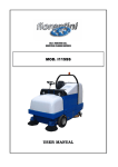
ING. O. FIORENTINI S.R.L. INDUSTRIAL CLEANING MACHINES SCRUBBING SWEEPING MACHINE MOD. I115SS GAS USER MANUAL MACHINE FEATURES AND TECHNICAL DATA I115SS-GAS Congratulations for your choice! FIORENTINI S.r.l. thanking you for the preference to our product, would like to remind you that FIORENTINI’s S.r.l production covers manufacture and marketing of industrial cleaning machines and is currently a leading company in this sector. Our tradition and competence guarantee technical quality of your choice; actually all our products are being built first quality materials through criteria that can give reliability, solidity and functionality satisfying every kind of customers. FIORENTINI has recently obtained the quality system certificate conforming to the requirements of UNI EN ISO 9001:2000. We wish therefore inviting you to contact us, unhesitatingly, for every kind of request, as technical or commercial; we’ll be pleased to be at your disposal for any information you may need. INDEX 1. GENERAL INFORMATION 1.1. 1.2. 1.3. 1.4. 1.5. 2. Symbols………………………………….…….........................……......…………..page Notes…….................................................…………...…………..............…...…......... Manual consulting…………......…………………………....….........………….………… Warranty..............................................................…………...…………...….…........... Conformity declaration…….........................................…...........………….…...……… MACHINE FEATURES AND TECHNICAL DATA 2.1. Identifying the machine……......…...............................….…………….….……........... 2.2. Description and components.……………...……………………………….…….…........ 2.3. Technical data………...................................…........……………………….....….......... 3. SAFETY 3.1. 3.2. 3.3. 3.4. 3.5. 3.6. 3.7. 3.8. 3.9. 4. Right use of the machine……....……………....…....……………….....…………........ Wrong use of the machine .…………………………………………………..………….. Suggested equipment…………………………………………………………… Operator qualify..............……………….......……………...…………............... Safety and warning devices ……………..................…...…………............ Safety systems...............................................…………..….…....…………........ Safety diagnostic signaling …………………………………………………. Other dangers……………………………………………………………………………… Security signals…………………………………………………………………... STARTING AND USE INSTRUCTIONS 4.1. Trasport and handling……...................….....................…....………….….….…........ 4.2. Storage……………..............................................…………….………….................... 4.3. How to unpack the machine...........................……………………........…..... 4.4. How to handle the unpacked machine.….…..........………………………..…….......... 4.5. Installation…...............................................................………………..……............. 4.5.1. Batteries installation……..........……..….......……………….…...….….........…...... 4.5.2. Battery charger installation…………………………………………………………… 4.6. Control devices……………………………………………………….. 4.6.1. Dashboard………………………………………………………………………… 4.7. Functioning…………………………………………………………………………….. 4.7.1. Preparing and starting the machine………………………………………………. 4.7.2. Choosing the right detergent………………………………………………………….. 4.7.3. Regulate the driving position ………………………………………………… 4.7.4. Rudder bar functioning…………………………………………………………….. 4.7.5. Detergent control…………………..…………………………………………………… 4.7.6. Squeegee adjustment………………………………………………………………… 4.7.7. Water discharge, recovery tank discharge and maintenance ……………… 4.7.9. Brushes replacement………………………………………………………………….. 4.7.10. Squeegee blades replacement………………………………………………………. 4.7.11 Driving wheel tire replacement ………………………………….. MACHINE FEATURES AND TECHNICAL DATA 5. I115SS-GAS MAINTENANCE 5.1. Periodic maintenance……………..……………..................….....…..…………........... 5.2. Batteries maintenance…………………………………………………………………….. 5.2.1. Hydrometry ………………………………………………………………………………. 5.2.2. Water filling up …………………………………………………………………………... 5.2.3. Charge limits……………………………………………………………………………… 5.2.4. Off duty or inactive batteries …………………………………………………………... 5.2.5. Battery charger technical features…………………………………………………… 5.2.6. Batteries disposal…………………………………………………………….. 5.3. Suction motor maintenance……………………………………………….. 5.4. Electrict equipment control………………………………………………………………. 5.5. Tests to be carried out…………………………………………… 5.6. Maintenance register…………………………………………………………………. 6. SERVICE 6.1. Service adresses............…………..................…………….................. 6.2. Claim report……………………………..…………...………………….…............ 7. VARIOUS SYSTEMS 7.1 7.2 7.3 7.4 Wiring diagram gas version………………………………………………………. Hydraulic diagram gas version………………………………………………………. Wiring diagram battery version………………………………………………………. Hydraulic diagram battery version………………………………………………………. GENERAL INFORMATION I115SS-GAS 1. GENERAL INFORMATION 1.1. SYMBOLS This symbol is used to get the operator’s attention on procedures or precautions to be followed in order to avoid damages to users or to the support This symbol is used to get the operator’s attention on general information. 1.2. PREMISE FIORENTINI S. r. l. is the only owner of this manual. The reproduction of all or part of the manual or the transmission to third parties with mechanic or electronic devices are vorbidden without a written manufacturer’s authorization. This manual is supplied to the customers in one original copy when differently specified during the order. This manual is supplied to the customer with the machine and it must be kept with it even when the machine has to be transferred. Please, keep the manual in a safe place and for all the machine lifetime. Purchaser is responsible for showing the manual to qualified people. In case of loss ask for a duplicate to FIORENTINI Co.. FIORENTINI S.r.l. is not responsible for any kind of damages caused by people or things due to the nonobservance of the instructions of this manual. FIORENTINI reserves the right to add at any time and without notice all the technical and commercial changes considered useful for the customer. Therefore data and information in this manual can be updated. 1.3. MANUAL CONSULTING This manual deals exhaustively with all arguments that are necessari for an easy and safe use of the machine as it is recommended by European Directives on product safety. Therefore we suggest to all authorized operators to read carefully this manual contacting FIORENTINI S.r.l. for any explanation. The manual has to be used every time the operator forgets a procedure or when new operators have to be trained. For publishing reasons, pictures and drawings can look different from the reality but without arising doubts. Special symbols and bold type and/or sloping get the attention of the reader on remarkable information in particularl for safety. The revision index is written on the left at the bottom of every page. The list of those pages that have been updated has to be found at the end of the manual. 1.4. WARRANTY Warranty conditions are stated as below when not differently specified in the order confirmation. WARRANTY OBJECT The machine has been designed and built for a long-lasting use without relevant problems. Anyway, if problems arise during the warranty period, FIORENTINI S.r.l. is engaged to repair or substitute for free those parts that are broken or damaged by defective materials, working defects or imperfect assembly. Warranty is not given for parts whose early breaking or wear and tear are due to: Non-respect of instructions included in this manual; • Breaking and/or changes made up without FIORENTINI’s approval; • Not-use of genuine spare parts; Rev. 000 20/12/04 4/66 GENERAL INFORMATION I115SS-GAS • Interventions made up by unauthorised personnel; • Missing maintenance; • Natural calamities. FIORENTINI S.r.l., its purchasers and its suppliers have the same warranty for the electric and expendable materials that are sold by external suppliers. WARRANTY CONDITIONS The warranty is granted for 24 months since the machine delivery date. This is a single warranty term and it cannot be extended. EXCEPTIONS Expandable materials like brushes, squeegee blades and materials whose lifetime cannot be predetermined are not under warranty. APPLICATION MODALITY Defective components must be sent back to FIORENTINI S.r.l. in order to establish the anomalies causes and apply therefore the warranty. Repair and replacement under warranty will be done in FIORENTINI’s workshop, by third parties or in loco. In case of repair or replacement in loco, energy sources and the use of particular equipment have to be paid by the customer himself. INTERVENTION DEMANDS Intervention demands must be sent to FIORENTINI Service Dpt. only after a careful analysis of the problem and its causes. Following information have to be given to FIORENTINI’s agent: • Serial number you get it from the silver label sticked on the machine (§ 2.1.); • Code and position of the component taken from the spare parts list (§ 7.2.); • A detailed description of the problem and its causes. The components considered under warranty are delivered ex works; those ones being substituted belong to FIORENTINI Co.. GOODS TO BE RETURNED In case of goods to be returned for warranty replacement, it is necessary to have a written acceptance from FIORENTINI technical department before sending them. All defective parts must be carefully packed in order to avoid further damages during transport. Goods must be shipped ex-warehouse and followed by : • • • serial number of the equipment where they were installed on; item code of the defective part; detailed description of the defect and of the condictions where it happened. In case of defective electric or electronic goods, please return them separately from other materials, in order to help us in dividing dangerous wastegoods and recicle the (RAEE) as DER 2002/96/CEE LOW. The machine warranty is no more available in case of the loss of the silver label. 1.5. CONFORMITY DECLARATION The conformity declaration is released with the machine and the user manual. Rev. 000 20/12/04 5/66 GENERAL INFORMATION I115SS-GAS DICHIARAZIONE CE DI CONFORMITA’ ING. O. FIORENTINI s.r.l. Loc. Rombola 50030 PIANCALDOLI (FI) ITALIA DICHIARIAMO SOTTO LA NOSTRA RESPONSABILITA’ CHE LA MACCHINA Marca FIORENTINI Tipo N° serie Anno di costruzione 2005 RISULTA IN CONFORMITA’ con quanto previsto dalle seguenti direttive e normative armonizzate comunitarie: DIRETTIVA COMUNITARIA DIRETTIVA MACCHINE 98/37/CEE DIRETTIVA BASSA TENSIONE 73/23/CEE DIRETTIVA COMPATIBILITA’ ELETTROMAGNETICA 89/336/CEE Ing. O. Fiorentini S.r.l. Il titolare Ing. O. Fiorentini Piancaldoli Luogo e data Rev. 000 Firma 20/12/04 6/66 MACHINE FEATURES AND TECHNICAL DATA I115SS-GAS 2. MACHINE FEATURES AND TECHNICAL DATA 2.1. IDENTIFYING THE MACHINE A silver label is sticked on the protection case of the steering column and clearly shows the data referring to the “CE” marking. PICTURE Nr. 2.1 The label has never to be removed and should always be kept readable. In case of damage t is necessary to ask for a duplicate. The autoscrubber machine cannot be sold without the label. 2.2. DESCRIPTION AND COMPONENTS This machine has been designed to clean the floor in three steps: floor sweeping, floor washing and water suction. It is available in four versions: battery, gasoil, petrol or GPL. The battery version is built with the following components: ¾ a electric engine, which is connected to two hydraulic pumps: one variable delivery pump and one fixed delivery pump; ¾ a hydraulic rear driving wheel which is connected to the hydraulic system and to the variable delivery pump. The pump is operated by the gas pedal; ¾ two side brushes; ¾ one central brush; ¾ a dust suction system; ¾ a recovery tank; ¾ three washing brushes behind the central brush; ¾ one squeegee; ¾ one solution tank made of ABS plastic; ¾ one recovery tank made of ABS plastic with flexible pipes for water suction and discharge; Rev. 000 20/12/04 7/66 MACHINE FEATURES AND TECHNICAL DATA ¾ I115SS-GAS a series of batteries (for the battery version), a gasoil or petrol or GPL engine (for the version with engine); ¾ steering wheel group; ¾ operator’s seat. The two sweeping brushes collect the dust and the central brush, that rotates in the opposite direction of the machine, put it into the recovery tank. A suction system has to put fine dust, that the sweeping brushes cannot collect, into the recovery tank. Both the sweeping brushes and the washing ones can operate at the same time, while the squeegee – in deep contact with the floor - intake water into the recovery tank. Please do not forget to start the filter shaker motor for the dust filter cleaning. This operation has to be done with open bucket and close to the discharge area. Thanks to the dashboard the operator can control all the machine functions, which are listed below: ¾ operate the side brushes and the central one of the sweeping group; ¾ operate the suction of the sweeping group; ¾ lift or lower the recovery tank; ¾ open or close the flap; ¾ operate the filter shaker; ¾ operate the parking brake lever; ¾ lift or lower the washing brushes plate; ¾ move on side the washing brushes plate; ¾ operate the washing brushes; ¾ control the detergent quantity; ¾ start the suction motor; ¾ lift or lower the squeegee; ¾ select forward or riverse gear; ¾ start or stop the machine; ¾ switch the flashing light on or off; ¾ switch the lights on or off. Rev. 000 20/12/04 8/66 MACHINE FEATURES AND TECHNICAL DATA The machine frame is made of zinc-plated or stainless steel in order to avoid oxidation I115SS-GAS which could compromise the machine reliability. FIORENTINI Co., taking the new CE safety rules into consideration, manufactures the machine following the CE directives about safety and health. The materials high quality, the high technology and FIORENTINI’s experience guarantee the performance and the reliability of this machine . Each machine is tested during the manufacturing process and the final check is done before the machine is shipped out. Rev. 000 20/12/04 9/66 MACHINE FEATURES AND TECHNICAL DATA 2.3. I115SS-GAS TECHNICAL DESCRIPTION DATI TECNICI – SPECIFICATIONS – CARACTERISTIQUES TECHNIQUES GAS (GPL) Alimentazione – Voltage – Alimentation Sistema di trazione – Drive system - Systeme de traction idraulica posteriore Larghezza di lavaggio – Scrubbing width – Largeur de 1150 mm nettoyage Larghezza squeegee – squeegee width – Largeur suceur 1350 mm N° spazzole – Brushes no. – Nr. des brosses 3 x Ø 380 mm Area pulita per ora – Working capacity up to – Rendement 8050 mq/h jusqu’à Serbatoio soluzione – Solution tank – Cuve solution 220 litri Serbatoio di recupero – Recovery tank – Cuve recuperation 210 litri Spazzola centrale- Main broom – Brosse centrale 850 mm x Ø 300 mm Spazzole laterali anteriori – Front side brushes – brosses 2 x Ø 400 mm laterales devant Superficie filtrante- filtering surface – surface filtrant 6 mq Capacità contenitori rifiuti- dirty container capacity – capacité 210 lt conteneur dechets Ruota posteriore – rear wheel – roue arriere 460 mm. Ruote anteriori – front wheels – roue avant 460 mm. Velocità marcia avanti – Forward speed – Vitesse en marche 7 km/h avant Velocità marcia indietro – Backward speed – Vitesse en marche 7 km/h arriére Guida – Drive - Conduite Man on board Peso in ordine di marcia senza carburante – Weight of the 1200 kg. machine without GPL Pendenza max. superabile in trasferimento – Highest slope – 13% Pente superable Pendenza max. superabile in lavoro – Highest slope during 10 % work Pendenza max. per una inversione a U – Highest speed for a U5% (3km/h) turn Rumorosità – noise level - Bruit < 78db (A) CARATTERISTICHE TECNICHE MOTORI – TECNICAL CHARACTERISTICS – CARACTERISTIQUES TECHNIQUE Motore trazione – Traction motor – Moteur des tracion BRIGGS & STRATTON DM 950P MG LPG Cylinders 3 Displacement 952 cc HP 31 HP – 23 kW Suction engine 2x36V 850W Motore spazzole – Brush motor – Moteur des brosses 3 x 36 V 900 W Motore aspirazione – Suction motor – Moteur d’aspiration 1 x 36 V 350 W 3500 rpm DIMENSIONI – DIMENSIONS Lunghezza – Length – Longueur Larghezza senza carter spazzole- Width without brushes carters – Largeur sans carter brosses Larghezza con carter spazzola - Width with brushes carters Largeur avec carter brosses Altezza con roll bar – Height with roll bar – Hauteur avec roll bar Rev. 000 20/12/04 2100 mm 1200 mm 1230 mm 1850 mm 10/66 MACHINE FEATURES AND TECHNICAL DATA I115SS-GAS PERFORMANCE Hydraulic 1900 mm. Electric Hydraulic Electric Electric Electric Hydraulic (pedal) Mechanical (lever) Steering wheel Turning radius Sweeping side brushes lifting Sweeping central brush lifting Washing brushes lifting Squeegee lifting Washing plate translation Service brake Parking brake Rev. 000 20/12/04 11/66 MACHINE FEATURES AND TECHNICAL DATA I115SS-GAS The above mentioned characteristics are not binding for the manufacturer; they can be changed without any notice . ING.O.FIORENTINI Co. is always at disposal for any information (par.7.1.). MEASUREMENT UNITS CONVERSION Lenght 1 inch = 1” = 25,4 mm Power 1 kW = 1,36 CV = 1,34 BHP Temperature T (K) = t (°C) + 273 / t (°F) = 1,8 t (°C) + 32 Pressure 1 bar =100 kPa = 14,5 psi Rev. 000 20/12/04 12/66 SAFETY I115SS-GAS 3. SAFETY 3.1. RIGHT USE OF THE MACHINE This machine can sweep and wash at the same time. It has been designed both for the industrial and outside cleaning. The engine version can be used on slopes not higher than 15% while the battery version on slopes not higher than 10%. The machine can reverse on sloping surfaces not higher than 5% for the engine version (3 km/h speed) and 3% for the battery version (2km/h speed). 3.2. WRONG USE OF THE MACHINE ¾ ¾ ¾ ¾ ¾ ¾ ¾ ¾ ¾ ¾ ¾ ¾ ¾ ¾ The machine cannot be driven by non-authorized personnel; The machine cannot wash sloping surfaces whose gradient is higher than 15% for the engine version and 10% for the battery version or surfaces with holes; The machine cannot be driven on sloping surfaces higher than 5% for the engine version (3 km/h speed) and higher than 3% for the battery version (2 km/h speed). The machine cannot be used in places with dangerous substances and in particular with explosive atmospheres or with a bad microclimate; The machine cannot clean surfaces with inflammable products; The machine cannot be used as a means of transport for people or other means of transport; The protection devices of the machine cannot be modified or tampered; Batteries must be recharged in a fanned room; The operator have always to respect safety rules; The engine version of the machine with internal combustion cannot be driven in not authorized places; The operator cannot use equipments or devices that can create problems to the machine working; The machine components cannot be modified without FIORENTINI’s authorization; The operator cannot use acids that can damage the machine; The operator has always to respect the rules written in the user manual. Please read carefully and do not cover the labels sticked on the machine. FIORENTINI S.r.l. is not responsible for a wrong use of the machine (see § 3.2.) 3.3. SUGGESTED EQUIPMENT In order to use the machine in a proper way, we suggest to use the FIORENTINI’s equipment and original spare parts. FIORENTINI S.r.l. Technical Dept. is always at your disposal to design components or parts for a particular use of machine as requested by the customer. Rev. 000 20/12/04 13/66 SAFETY 3.4. I115SS-GAS OPERATOR’S QUALIFY The scheme below sumarizes the operator qualify requested for each kind of operation. OPERATION OPERATOR’S QUALIFY Driving/control of the machine Trained operator Installation/ disinstallation Mechanical parts maintenance Fiorentini technician Fiorentini technician Electric parts maintenance Fiorentini technician Cleaning maintenance Trained operator Dismantling and demolition Fiorentini technician FIORENTINI S.r.l. suggests to train the operator before using the machine. The operator also must be trained about safety rules and carefully read this manual. FIORENTINI S.r.l. is not responsible for any possible damage to people and/or things caused by the non-observance of the instructions dealt within this manual. 3.5. SAFETY AND WARNING DEVICES • It is absolutely forbidden to tamper or disconnect safety and warning devices while the machine is working; • It is important to check periodically safety and warning devices (see § 5.1.). Side brushes protection I115SS is equipped with three nylon brushes that rotate while the machine is working. A steel case on each side brush avoid to reach dangerous areas. These cases can be only willingly removed. Central brush protection I115SS is equipped with a central brush that rotates while the machine is working. A steel case avoid to reach dangerous areas. These cases can be only willingly removed. I115SS is equipped with several warning devices: ¾ Warning device ¾ ¾ ¾ Rev. 000 One acustic warning device like a claxon. It has to warn people who are near the machine while its operating; One intermittent bleeper to warn people while the machine is reversing; Two flashing yellow lights to signal the machine operating.con luci gialle lampeggianti per la segnalazione di macchina in funzione. Headlights to work in places with few light. 20/12/04 14/66 SAFETY 3.6 I115SS-GAS SAFETY SYSTEMS The machine is equipped with the following safety systems. ¾ Socket (picture 4.5), the same socket used for the battery charger. In case of emergency, this socket must be taken away from the plug by means of its handle. The operator must be trained about safety rules. Do never restore this safety system before the problem has been sorted out. If it is necessary ask for the technician help. ¾ Insufficient battery charge: the electronic card, that controls all the machine functions except for the traction, disconnect all these functions when the battery charge is lower than 20%. In this way the batteries’ lifetime can be longer. ¾ Emergency switch (battery version): the machine is equipped with an emergency button under the driver’s seat. If the operator is not aboard, the machine does not start. Moreover, the machine stops automatically if the operator forgets to switch the machine off. In this way the operator must seats again on the machine, switch the machine off, wait for a few seconds and start the machine again. ¾ Ammeter: the machine is equipped with an ammeter on the dashboard, which controls the washing brushes pressure. The operator has not to overcome the yellow line for a slight cleaning; the green line for a normal cleaning; the red line for a brief cleaning. ¾ Safety stopper: the machine is equipped with red safety stopper under the recovery tank. The operator must use it every time he/she needs to maintain the recovery tank. Attention: the operator has not to work with the machine with leds always on the red line of the ammeter. Rev. 000 20/12/04 15/66 SAFETY 3.8. I115SS-GAS OTHER DANGERS FIORENTINI S.r.l. analyzes – starting from the design of the machine - all the dangers that can occur while the machine is operating in order to prevent or at least low the operator’s accidents. Thanks to a series of signals on the machine the operator can avoid many risks that can occur. CRUSHING DANGERS This kind of danger can occur: • during the side brushes regulation; • during the batteries recharge because of the batteries cover fall (battery version); • during the hydraulic oil filling because of the cover batteries fall (battery version); • while checking the filter of the waste tank; • during the squeegee regulation; • while replacing the central brush or the washing brushes; • while emptying the waste tank. Whilst regulating the side brushes, the central brush and the central washing brushes the ignition key must be kept away from the dashboard in order to avoid the casual starting of the machine. Whilst the batteries recharge, the operator must pay attention that any parts of his/her body enter the batteries room. Special labels sticked on the cartes of the brushes or on the recovery tank prevent dangers to the operator (see § 3.7.). SQUASHING AND SHEARING This kind of danger can occur: • while emptying the waste tank; • while installing or replacing the batteries. While the operator is emptying the waste tank, nobody must be near the machine in order to avoid accidents. Squashing and shearing danger is highlighted by special labels sticked on the case of the steering column (see § 3.7.). Rev. 000 20/12/04 16/66 SAFETY I115SS-GAS TURNOVER This kind of ranger can occur: • during the normal operating of the machine when you exceed sloping limits as specified in the manual and you use the machine to clean disconnected surfaces or with holes and high depressions (photo 3.2) • Do not use the machine to wash sloping surfaces higher than 10% or surfaces with holes or depressions which might compromise the stability of the machine. FIORENTINI is not responsible for accidents occurred to people or things provoked by a wrong use of the machine, i.e. using the machine on surfaces which can compromise its stability. The purchaser must stick proper labels on the machine to show the operator its right use. BURNING DANGER This kind of danger can occur: • during the check up of the oil engine. Whilst changing or checking the engine oil make sure that the machine has been switched off a few minutes ago before opening the rear case, in order to avoid to touch hot parts of the machine. Special labels sticked on the case of the steering column prevent dangers to the operator (see § 3.7.). Rev. 000 20/12/04 17/66 SAFETY 3.9. I115SS-GAS SAFETY SIGNALS Rev. 000 DANGERS Dangers’ signals are triangular with black pictures on a yellow background PROHIBITIONS Prohibitions’ signals are round with black pictures and a red stripe What is it? This signal forbids to remove the protection of pieces in movement. What to do During the installation or the maintenance make sure that the ignition key is not in the dashboard before removing the mobile protections. While the machine is operating make sure that all covers are well fixed. What is it? Crushing danger: it can be due to parts in movement of the machine. What to do During the installation or the maintenance make sure that the ignition key is not in the dashboard before removing the mobile protections. 20/12/04 18/66 SAFETY Rev. 000 I115SS-GAS What is it? Crushing danger: it can be due to parts in movement of the machine. What to do During the installation or the maintenance make sure that the ignition key is not in the dashboard before removing the mobile protections. What is it? This signal forbids to remove the protection of pieces in movement. What to do During the installation or the maintenance make sure that the ignition key is not in the dashboard before removing the mobile protections. While the machine is operating make sure that all covers are well fixed. What is it? Crushing danger: it can be due to parts in movement of the machine. What to do During the installation or the maintenance make sure that the ignition key is not in the dashboard before removing the mobile protections. 20/12/04 19/66 SAFETY I115SS-GAS What is it? Explosion danger: it may occur while recharging the batteries because of hydrogen spread. What to do During the batteries recharge, please place the machine under a suction chemney or in a ventilated area and keep it away from heat and corrosive substances. What is it? Crushing danger: it can be due to parts in movement of the machine. What to do During the installation or the maintenance make sure that the ignition key is not in the dashboard before removing the mobile protections. The purchaser must replace danger signals on the machine if they are damaged. It is absolutely forbidden to remove or temper danger signals. Rev. 000 20/12/04 20/66 STARTING AND USE INSTRUCTIONS 4. 4.1. I115SS-GAS STARTING AND USE INSTRUCTIONS TRANSPORT AND HANDLING The machine is delivered to the purchaser in a proper package (see picture 4.1 below). A black arrow on the package indicates the barycentre. This arrow must be in the middle of the elevator or transpallet forks. The package must be carefully handled. Do not place one package on another one. If agrred with the purchaser, the machine can be delivered without package, placed on a pallet and fixed by means of straps. The purchaser must make sure that the machine has not been damaged during the transport and that all papers are on the machine. Otherwise, the purchaser must immediately contact FIORENTINI in order to sort out the problem. The purchaser is responsible for the transport of the machine if not differently agreed with FIORENTINI. The machine must be handled with proper devices as stated in the scheme below. PACKAGE HANDLING EQUIPMENT PICTURE Pallet Fork elevator Nr. 4.2 None Fork elevator or crane truck with a two-band-sling and equalizer Nr. 4.3 The bands used for lifting the machine up must have the same loading capacity as the machine load. Handling operations must be done without causing a loss of stability of the machine. Otherwise, the machine can be damaged or the operator can de in danger. FIORENTINI suggest to use authorized personnel (see § 2.3.) to handle the machine. LOADING SYSTEM PICTURE NR. 4.2 Rev. 000 PICTURE NR. 4.3 20/12/04 21/66 STARTING AND USE INSTRUCTIONS I115SS-GAS 4.2. STORAGE The machine must be stored in a closed and dry place if not immediately installed in order to keep every part safe. Relative humidity must be lower than 80% and the storage temperature must be between 3°C ≤ t ≤ + 45 °C. 4.3. HOW TO UNPACK THE MACHINE ¾ Cut the straps paying attention to the back spring; ¾ Lay the machine on the floor. 4.4 HOW TO HANDLE THE UNPACKED MACHINE ¾ Check the machine and install the batteries if not already installed; ¾ For a brief transport of the machine, please disconnect the batteries cables and remove brushes and squeegee; for a longer transport, please use the original package of the machine. Rev. 000 20/12/04 22/66 STARTING AND USE INSTRUCTIONS 4.5. I115SS-GAS INSTALLATION Installation must be carried out by authorized personnel after reading this manual. 4.5.1 BATTERIES INSTALLATION (battery version) Please follow the instructions below to install the batteries: ¾ Lift the batteries cover up by means of the handle (see picture nr. 4.3 detail nr. 3); ¾ Unscrew the piston and release the side support to remove the cover and its support (see picture nr. 4.3 details nr. 1-2); ¾ Insert from the top the batteries with a proper equipment; ¾ Clean the surfaces for the connections; ¾ set the cover and its support up again; ¾ close the batteries cover. Important: install the batteries with empty tank. 1 3 Rev. 000 2 PICTURE Nr. 4.3 20/12/04 23/66 STARTING AND USE INSTRUCTIONS 4.5.2 I115SS-GAS BATTERY CHARGER INSTALLATION (battery version) Batteries must be recharged in a place equipped with a proper suction system of gases spread during this operation. Otherwise, batteries must be charged in a ventilated and dry place far from heat sources and corrosive substances. Protect the electric network with a delayed switch or with a fuse whose capacity is higher than the battery charger maximum input. Control the battery outlet polarity. Connect the battery charger to the machine socket PICTURE Nr. 4.4 Rev. 000 20/12/04 24/66 STARTING AND USE INSTRUCTIONS I115SS-GAS 4.5.3 MACHINE STARTING (diesel/petrol version) The autoscrubber ICM38GAS can be started only when you are completely sure that all the components and devices of the machine are efficient. This is why, well trained FIORENTINI technicians do a strict control while producing the machine and an accurate final test. Anyway, FIORENTINI suggests to do another test before starting the machine. Please see the scheme below. Result Test √ X Hydraulic oil level Engine oil level Engine cooling water level Wheels brake Pilot lights functioning If the result of the test is positive, the machine can be started. On the contrary, please contact immediately FIORENTINI service. The test above must be periodically done in order to keep the machine always efficient. The machine must be started by authorized personnel. Rev. 000 20/12/04 25/66 STARTING AND USE INSTRUCTIONS 4.6. I115SS-GAS CONTROL DEVICES 4.6.1. DASHBOARD The dashboard is made of a series of switches that activate or disactivate all the machine functions. The function of each switch is shown by a picture. Picture 4.5. shows the dashboard of the machine and the switches function is explained in the scheme in the following page. 1 2 3 4 5 9 6 10 11 7 8 12 PICTURE Nr. 4.5 1 2 3 4 5 6 7 8 9 10 11 12 13 Rev. 000 Washing brushes plate switch Flashing light switch Lights switch Filter shaker switch – waste tank suction switch Horn button Squeegee suction switch Waste tank lever Flap lever Front brushes switch Central brush lever Red pilot light – flap off Green pilot light – flap on Ammeter led (battery version) 20/12/04 26/66 STARTING AND USE INSTRUCTIONS I115SS-GAS 13 14 15 16 14 15 16 17 18 19 20 21 22 Rev. 000 17 Oil indicator Battery charger indicator Water temperature indicator Water cock lever Parking brake Gas pedal GAS button Key switch Starting 20/12/04 27/66 STARTING AND USE INSTRUCTIONS I115SS-GAS SYMBOLS ON THE DASHBOARD Rev. 000 Battery charge pilot light Filter shaker Key switch Battery charge status Flashing light Waste tank down Horn Waste tank up Squeegee suction Bucket on Parking brake Bucket off Sweeper suction on Washing brushes plate out Solution cock Washing brushes plate in Squeegee up Washing brushes on Squeegee down Washing brushes off Central brush on Side sweeping brushes on Central brush off Side sweeping brushes off Ammeter (battery version) Attention: hot muffler Oil drainage Brushes plate translation 20/12/04 28/66 STARTING AND USE INSTRUCTIONS 4.7. I115SS-GAS FUNCTIONING Machine starting Glow plugs Battery charge Oil pressure Engine temperature pilot light The operator has to turn clockwise the key in the dashboard until he/she hears a click. Then the operator has to wait for a while until the glow plugs pilot light switches off (see detail 7 in picture nr. 2) and turn clockwise the key again in order to start the engine. Before starting the sweeping scrubbing machine, please check the oil level into the hydraulic oil tank. The oil level must be between the first and the second notch of the oil dipstick. If the oil level is unsufficient, please top it up after having switched the machine off and kept the ignition key away from the dashboard. Important: before starting the machine, please make sure that the gas lever is in the same position as shown in the picture below. The operator can move this lever towards the dashboard only after the engine start. In this way the number of revolutions increases. Rev. 000 20/12/04 29/66 STARTING AND USE INSTRUCTIONS I115SS-GAS I115SS can sweep and wash the floor at the same time. Please follow the instructions below for a perfect cleaning: - start the side brushes, the central brush and the sweeping brushes suction; - low the squeegee; - start the washing brushes; - open the solution cock and regulate the solution quantity; - press the suction switch; - close the water cock because it does not depend on the feed pedal. The operator, thanks to his/her experience, has to choose the right kind of brush and detergent for the surfaces that has to be washed and to decide if the floor needs a second washing. If the floor is particularly dirty, the operator has to: - sweep the floor; - wash the floor with washing brushes down and squeegee up; - open the water cock; - leave the solution on the surface to dissolve the dirt; - do a second washing with brushes and squeegee down, the suction activated and the solution solenoid valve open. The machine is equipped with a particular device that translate the brushes plate to the right in order to do a better cleaning. This function allows the brushes replacement, too. The engine version of the machine has always to work at ¾ of its peak rpm. In this way both the brushes and its motors can work correctly. NB: Before any operation, make sure that all protections are well fixed. Rev. 000 20/12/04 30/66 STARTING AND USE INSTRUCTIONS 4.7.1 I115SS-GAS PREPARING AND STARTING THE MACHINE If the machine is connected with the battery charger, the operator must firstly disconnect the battery charger plug from the batteries one and connect the batteries plug with the power supply plug (see picture 4.6. – battery version). Secondly, the operator must fill water lifting the recovery tank up and turning the cap (see detail nr. 1 in picture nr. 4.7.). Moreover, the operator has to check the hydraulic oil level lifting the batteries cover up (see picture nr. 4.8 detail 1) and unscrewing the red cap under the electric system (see picture nr. 4.8 detail 1). Now the operator can seat on the machine and start it. 1 PICTURE Nr. 4.6 1 1 Rev. 000 PICTURE Nr. 4.7 20/12/04 31/66 STARTING AND USE INSTRUCTIONS I115SS-GAS 1 PICTURE Nr. 4.8 4.7.2 CHOOSING THE RIGHT DETERGENT Choosing the right detergent is very important for a perfect cleaning. A too strong detergent could damage the surface. A good quality detrgent has to produce little foam. Alternatevely, the operator can add an antifoaming additive or 50 cc of wine vinaigre in the recovery tank in order to avoid the suction motor damage. Make sure that the detergent is suitable for the dirty surface. FIORENTINI S.r.l. is not responsible for damages provoked by too aggressive detergents. Rev. 000 20/12/04 32/66 STARTING AND USE INSTRUCTIONS 4.7.3 I115SS-GAS REGULATE THE DRIVING POSITION By means of the lever (see detail nr. 1 in picture nr. 4.9.) for the steering column regulation, the operator can pull backward or push onward the steering wheel in order to have a driving position which fits his/her body. 1 Rev. 000 20/12/04 PICTURE Nr. 4.9 33/66 STARTING AND USE INSTRUCTIONS 4.7.4 I115SS-GAS RUDDER BAR FUNCTIONING The rudder bar of this machine is composed by: ¾ Accelerator pedal (see detail 3 in picture 4.10). The operator has to press the front side of the pedal for the forward gear or the back side of the pedal for the reverse gear; ¾ Service brake: it is activated by a pedal placed on the left side of the footboard (see detail 1 in picture 4.10); ¾ The service brake is activated by means of a lever (see detail 2 in picture 4.10): the operator has to pull the lever up until the developed pressure can lock the machine; ¾ The brake is hydraulic. Its oil tank is placed in the front side of the machine, behind the waste tank (see detail 4 in picture 4.10). 4 2 5 1 3 4 PICTURE Nr. 4.10 Rev. 000 20/12/04 34/66 STARTING AND USE INSTRUCTIONS 4.7.5 I115SS-GAS DETERGENT CONTROL During the washing the operator can control the detergent quantity by means of a cock, which is at the bottom of the machine on the left inside the protection rubber (see detail nr. 5 in picture 4.10.). 4.7.6 SQUEEGEE ADJUSTMENT The squeegee has to be well regulated in order to have a perfect dry system. This kind of squeegee can perfectly suck water, which flows into the suction pipe, but it must be parallel to the surface. ¾ Remove the ignition key from the dashboard in order to avoid the casual starting of the machine. ¾ By means of the exagonal tie rods regulate the squeegee inclination (see detail 1 in picture nr. 4.11) ¾ Regulate the squeegee pressure by means of the ring nuts that control the distance between the wheels of the squeegee and the floor (see detail 1 in picture nr. 4.12). 1 PICTURE Nr. 4.11 PICTURE Nr. 4.12 Make sure that the two wheels of the squeegee are well regulated in order to keeps both its blades parallel to the floor. Rev. 000 20/12/04 35/66 STARTING AND USE INSTRUCTIONS I115SS-GAS 4.7.7 WATER DISCHARGE AND WASTE TANK EMPTYING This machine is equipped with two pipes for water discharge (picture 4.13): ¾ A pipe for the recovery tank discharge (see detail nr. 1 in picture nr. 4.13); ¾ A portole for the recovery tank cleaning (see detail nr. 2 in picture nr. 4.13); ¾ A suction pipe (see detail 3 in picture nr. 4.13). If you need to discharge water from the tanks, you have to place the machine on a dump well, release the pipe of the tank and open the rubber cap at the end of the pipe itself. 2 1 3 PICTURE Nr. 4.13 Rev. 000 20/12/04 36/66 STARTING AND USE INSTRUCTIONS I115SS-GAS Waste tank emptying The operator has to follow the instructions below in order to empty the waste tank: ¾ Stop and lift the sweeping brushes up; ¾ Close the suction lever; ¾ Close the bucket; ¾ Press for a few seconds the filter shaker switch; ¾ Lift the waste tank up; ¾ Place the waste tank on a waste bin; ¾ Open the bucket for the waste discharge; ¾ Press the shaker filter switch; ¾ Keep away from the waste bin and sink the waste tank. Pay attention that nobody is near the machine during this operation. PICTURE Nr. 4.14 Make sure that THE RED SAFETY STOPPER IS WELL FIXED to the hydraulic jack when the recovery tank needs to be maintenained. Afterwards, REMOVE THE SAFETY STOPPER from the hydraulic jack and fixed to its support. Rev. 000 20/12/04 37/66 STARTING AND USE INSTRUCTIONS 4.7.8 I115SS-GAS SWEEPING BRUSHES REPLACEMENT Central brush replacement ¾ Open the door on the right side of the machine (see detail 1 in picture nr. 4.15); ¾ Unscrew the bolt (see detail 2 in picture nr. 4.15) that hold the rubber sheet; ¾ Remove the sheet (see detail 3 in picture nr. 4.15); ¾ Remove the dust cover rubber (see detail 1 in picture nr. 4.16); ¾ Unscrew the knob (see detail 1 in picture 4.17) and open the brush support (see detail 2 in picture 4.17); ¾ Remove the brush (see detail 1 in picture 4.18): ¾ Set the brush up again (see detail 1 in picture nr. 4.18) ¾ do now the opposite instructions. 3 1 2 1 1 PICTURE NR. 4.16 PICTURE NR. 4.15 2 PICTURE NR. 4.18 1 PICTURE NR. 4.17 Rev. 000 20/12/04 38/66 STARTING AND USE INSTRUCTIONS I115SS-GAS PICTURE NR. 4.18 Side brush replacement ¾ ¾ Unscrew the nuts (see detail 1 in picture nr. 4.19) and remove the brush; Replace the brush and screw the nuts again. PICTURE Nr. 4.19 Rev. 000 20/12/04 39/66 STARTING AND USE INSTRUCTIONS 4.7.9 I115SS-GAS WASHING BRUSHES AND BLADES REPLACEMENT Please follow the instructions below: ¾ Remove the ignition key from the dashboard in order to avoid the accidental start of the machine after having translated the brushes plate outside. ¾ Remove the split pin that hold the bumper wheel support pin (see detail 1 in picture nr. 4.20); ¾ Remove the right brush turning it until you can see the pin, pull the pin and remove the brush (see detail 2 in picture 4.20); ¾ Set the new brush up: place it under the exagonal support and press it up (see detail 3 in picture nr. 4.20); ¾ Start now the machine, place the brushes plate in its original position and switch the machine off; ¾ Follow the same instructions for the left and central washing brush; ¾ After having replaced the brushes, the operator has to set the cases and the split pin up again; ¾ Blade replacement: the operator has to unscrew the screws on the case and replace the blade. 1 3 FIGURA N° 4.20 2 Before starting the machine again, please make sure that all the protection cases are well set up. Rev. 000 20/12/04 40/66 STARTING AND USE INSTRUCTIONS 4.7.10 I115SS-GAS SQUEEGEE BLADES REPLACEMENT Squeegee blades must be replaced when their hedges are worn. A perfect hedge allows a perfect dry (picture 4.19). Please follow these instructions to replace the squeegee blades: ¾ Remove the squeegee from the machine and lay it on a table; ¾ Turn the lever (see detail 2 in picture 4.21), unloose the steel strip and the two side wing nuts; ¾ Remove the steel strips (see details 1 and 3 in picture nr. 4.21); ¾ Do now the opposite operation, set the new blades up and regulate the squeegee; ¾ Follow the same instructions to replace the front blade. PICTURE Nr. 4.21 Rev. 000 20/12/04 41/66 STARTING AND USE INSTRUCTIONS 4.7.11 I115SS-GAS HOW TO REPLACE THE SUCTION FILTER OF THE SWEEPING GROUP AND THE SHAKER FILTER MOTOR The filter shaker motor has to clean the filters from the dust by shaking them. The dust fall into the waste tank. If the shaker motor looses its function, it has to be replaced as follows: ¾ Remove the ignition key from the dashboard in order to avoid an accidental start of the machine; ¾ Open the bonnet of the machine (see detail 1 in picture nr. 4.21); ¾ Pull the cover of the tank up (see detail 1 in picture nr. 4.22); ¾ Unscrew the two knobs (see detail 2 in picture 4.22) that fasten the filter; ¾ Remove the support of the shaker filter motor (see detail 3 in picture 4.22); ¾ Disconnect the connectors (see detail 4 in picture 4.22) of the filter shaker motor; ¾ Replace the damaged or obstructed filter (see detail 5 in picture 4.22); ¾ do now the opposite instructions. 4 3 2 1 PICTURE Nr. 4.22 Rev. 000 20/12/04 5 PICTURE Nr. 4.23 1 42/66 STARTING AND USE INSTRUCTIONS I115SS-GAS 4.7.12 HYDRAULIC OIL TOPPING UP The oil level does not change, but when there are leaks from the unions or the hydraulic pipes. In this case, the operator has to top the hydraulic oil up from the cap (picture 4.24) after having lifted the batteries cover up. 1 PICTURE Nr. 4.24 4.7.13 Engine oil and filter: check and replacement ¾ ¾ ¾ ¾ ¾ ¾ ¾ Keep the ignition key away from the dashboard; Lift the bonnet that holds the seat; Open the side case (see detail 1 in picture 4.25); Remove the oil pipe (see detail 2 in picture 4.25); Turn the oil cap (see detail 3in picture 4.26); Unscrew the oil filter (see detail 3 in picture 4.26); When the oil pipe is completely empty, put it again into the side case (see detail 4 in picture 4.26); set a new oil filter up; fill the engine with oil as shown into the engine user manual; ¾ Check the oil level with the dipstick (see detail 4 in picture 4.25); ¾ Screw the oil cap and close the bonnet. 4 1 Rev. 000 5 6 2 20/12/04 43/66 STARTING AND USE INSTRUCTIONS I115SS-GAS 4.7.14 Air filter replacement ¾ ¾ ¾ ¾ ¾ ¾ Keep the ignition key away from the dashboard; Lift the bonnet that holds the seat; Unhook the two stoppers of the filter support (see detail 1 in picture 4.27); Remove the air filter and replace it with a new one (see detail 2 in picture 4.27); Close the support by means of the two stoppers (see detail 1 in picture 4.27); Close the bonnet. 2 1 PICTURE Nr. 4.27 Rev. 000 20/12/04 44/66 MAINTENANCE I115SS-GAS 5. MAINTENANCE 5.1. PERIODICAL MAINTENANCE A periodical maintenance is very important. Please write down in the format you find below all the interventions done on the machine. • Trained personnel only can service the machine and especially electric and electromechanical parts by means of suitable tools and equipments. • Make reference to FIORENTINI S.r.l. only for service and spare parts (§ 7.1. and § 7.2.). OPERATION INTERVENTION HOW OFTEN Clean the recovery tank and the oil filter of the suction motor Cleaning Do not use corrosive substances. a Do not use bolts of water. • Check the suction pipes and the squeegee ¾ Check the rubber suction blades of the squeegee ¾ Check the water battery level • Check the filter of the clean water tank Check and regulate the breaking system Check the connection of the battery cables Check the brushes of each motor ¾ Check the safety devices Check the electric system Clean the recovery tank and the oil filter of the suction motor Check up Cleaning 5.2 Every day • Every week Every 15 days Every month Every 3 months Every 6 months Every year Every year Every day ENGINE MAINTENANCE In order to maintain the internal combustion engine, the operator has to check: ¾ ¾ ¾ ¾ ¾ ¾ ¾ ¾ ¾ the engine oil level every 50 hour-work and replace it every 150 hour-work; the coolant level every 50 hour-work; the air filter (replace it every 100 hour-work); the fuel filter (replace it every 250 hour-work); the engine oil filter (replace it every 300 hour-work); the hydraulic oil filter (replace it every 750 hour-work); the tension of the alternator belt every 250 hour-work; the injectors setting and cleaning every 1000 hour-work; the regulation of the equalizers clearance every 1000 hour-work. Please make reference to the engine user manual for any other control. Rev. 000 20/12/04 45/66 MAINTENANCE 5.3 I115SS-GAS BATTERIES MAINTENANCE (battery version) ¾ The operator has to check the batteries charge when the machine is on duty by means of the indicator on the dashboard. The operator must keep the battery room open during the batteries recharge. Moreover: ¾ ¾ ¾ ¾ ¾ Rev. 000 It is forbidden to use flames and/or to smoke near the batteries; Pay attention to the battery acid; Do not develop sparks near the batteries; Pay attention to the batteries gazes, which can burst; Do not invert battery polarities. 20/12/04 46/66 MAINTENANCE 5.2.1 I115SS-GAS HYDROMETRY In order to check the batteries hydrometry the operator has to follow the instructions below: ¾ By means of a hydrometre draw a small quantity of electrolyte so that the floater reaches the surface; ¾ Make sure that the floater inside the hydrometre is not blocked; ¾ For a new measurement, after having filled the batteries with distilled water, the operator has to wait until the liquid inside each battery becomes homogeneous. 5.2.2 WATER FILLING UP ¾ Fill distilled water up in each battery cell before the recharge. The liquid inside the batteries has to be of 6 mm. over the plates; ¾ 5.2.3 The operator has to repeat the same operation every time the level decreases (every week). CHARGE LIMITS It is not necessary to recharge the batteries if the hydrometry, after a work day, is not under 1,24 (28 Bè). The highest suggested temperature is 45°C. If the electrolyte temperature increases more than 10/12 °C compared to the outside temperature, the batteries can be overcharged. 5.2.4 OFF DUTY OR INACTIVE BATTERIES Inactive batteries looses their automatically their charge. If batteries do not continually work, the operator has to: ¾ Charge the batteries once a month with a ‘final’ stream intensity until gas is spread and the batteries voltage and weight are constant for 3-4 hours. This operation has to be done even if the absolute weight is high; ¾ Rev. 000 Keep the batteries in a dry room. 20/12/04 47/66 MAINTENANCE 5.2.5 I115SS-GAS BATTERY CHARGER TECHNICAL FEATURES The battery charger has to show the features listed in the scheme below: IN OUT 230V, 50Hz, 5A 36V, 30A See § 2.3 TECHNICAL DATA for the batteries technical features. 5.2.6 BATTERIES DISPOSAL Old batteries are toxic wastes and they have to be thrown in a suitable and authorized place for the batteries disposal. For a short storage, old batteries must be located in an authorized room. Moreover, they must be stored in sealed plastic tanks, whose capacity is not lower than the electrolyte. Rev. 000 20/12/04 48/66 MAINTENANCE 5.3 I115SS-GAS SUCTION MOTOR MAINTENANCE The suction motor has to be checked up and cleaned. Every six months motor brushes have to be checked and replaced if it is necessary. To maintain the suction motor please follow the instructions below: ¾ Take the ignition key off the dashboard, disconnect the plug (see detail 3 in picture 5.1), remove the steel plate that fixes the suction motor and the motor itself (see detail 1 in picture 5.1); ¾ Remove the sponge filter under the motor, wash it and put it again in its position; ¾ Check the motor fan through the hole in the front side of the suction motor; ¾ Remove the plastic cover, lossen the screws and both the brushes supports and check the motor brushes (see detail 2 in picture 5.1); ¾ Do now the opposite operations to set everything up again. 1 3 4 5 2 PICTURE Nr. 5.1 Rev. 000 20/12/04 49/66 MAINTENANCE 5.4 I115SS-GAS ELECTRIC EQUIPMENT CONTROL It is very important to check the electric system up every two years. Disconnected cables or burnt cables must be immediately replaced. Interventions on the electric system must be carried out by a trained technician. Every kind of intervention not explained in the operator manual must be carried out by FIORENTINIs technicians. 5.5 Tests to be carried out As far as the maintenance of the gasoil, petrol or GPL version is concerned, the operator has to follow the engine user manual. PERIODICAL CHECKS Clean the recovery tank Clean the suction filter engine Check the hydraulic oil level Check the blades and the suction pipes of the squeegee Check the brake oil level Check the filter of the clean water tank (optional) Check the battery Check the radiator fins (machine with endothermic engine) Check the coal brush of each motor Check the electric system Check the safety devices Hydraulic oil filter replacement Hydraulic oil change Translator plate lubrication Check the gaskets Check if the dust filter is obstructed Check the lubrication of the steering wheel bearing Check the lubrication of the waste tank rotation axle Check and clean the clean water filter (optional) Rev. 000 Every Every Every Every Every Every Every Every Every Every 10 20 50 125 250 500 750 1000 2500 5000 hours hours hours hours hours hours hours hours hours hours x x x x x x x x x x x x x x x x x x x 20/12/04 50/66 MAINTENANCE 5.6. I115SS-GAS MAINTENANCE REGISTER DATE Rev. 000 OPERATOR INTERVENTION 20/12/04 SIGNATURE 51/66 TECHNICAL ASSISTENCE I115SS-GAS 6. TECHNICAL ASSISTENCE 6.1. SERVICE ADDRESSES Do not hesitate to contact FIORENTINI S.r.l. service for any kind of information or request. Most of the technical problems can be sorted out with short intervention. This is why FIORENTINI S.r.l. suggest to read carefully this manual before using the machine. On the contrary, if the customer needs a FIORENTINI’S technician, please inform us about the problem in order to sort it out with the right material. Rev. 000 20/12/04 52/66 TECHNICAL ASSISTENCE 6.2 I115SS-GAS CLAIM REPORT Please, fill in the format below if the machine shows particular problems. Operator: Company: Operator’s name: Role: Date: Signature: Machine description: Machine: Type: I115SS-GAS Purchase date: Warranty: S.N.: YES NO Work hours: Where does the machine normally work? Fault: Code of the defected component: Description: Fault: Mechanical component Wrong functioning Electric system Engine Fault short description: Missing component Estremely noisy Water leak Other Customer’s suggestion: Rev. 000 20/12/04 53/66 TECHNICAL ASSISTENCE I115SS-GAS 7. SCHEMI IMPIANTI 7.1 IMPIANTO ELETTRICO (GAS) Rev. 000 20/12/04 54/66 TECHNICAL ASSISTENCE Rev. 000 20/12/04 I115SS-GAS 55/66 TECHNICAL ASSISTENCE Rev. 000 20/12/04 I115SS-GAS 56/66 TECHNICAL ASSISTENCE Rev. 000 20/12/04 I115SS-GAS 57/66 TECHNICAL ASSISTENCE I115SS-GAS 7.2 IMPIANTO IDRAULICO (GAS) Rev. 000 20/12/04 58/66 TECHNICAL ASSISTENCE I115SS-GAS 7.3 IMPIANTO ELETTRICO (BATTERIA) Rev. 000 20/12/04 59/66 TECHNICAL ASSISTENCE N.Position Code Num 115.12.001 PY756 115.12.002 PY609 115.12.003 PY608 115.12.004 PY032 115.12.005 PY745 115.12.006 IN053 115.12.007 IN002 115.12.008 IN008 115.12.009 PY727 115.12.010 MI068 115.12.011 IN020 115.12.012 MO5039 115.12.013 MA039 115.12.014 PY214 115.12.015 PY526 115.12.016 PY527 115.12.017 BT097 115.12.018 PY536 115.12.019 PY535 115.12.020 PY232 115.12.021 PY205 115.12.022 PY157 115.12.023 PY747 115.12.024 PY299 115.12.025 PY300 115.12.026 PY5027 115.12.027 PY5026 115.12.028 SL004 115.12.029 PY5025 115.12.030 PY5028 115.12.031 PY5023 115.12.032 MA038 115.12.033 MA038 115.12.034 MO379 115.12.035 CW231 115.12.036 PY744 115.12.037 PY418 115.12.038 MO181 115.12.039 KIT636 115.12.040 KIT635 115.12.041 GL018 115.12.042 PY761 Rev. 000 Qta 1 1 1 3 2 1 1 1 1 1 2 1 1 2 1 1 1 1 2 2 3 2 1 5 5 1 1 1 1 5 1 1 1 3 1 1 1 2 1 1 1 1 Descrizione CONNETTORE 11 POLI PORTA-MASCHIO CONNETTORE NERO PER MOTORE ASPIRAZI CONNETTORE ROSSO PER MOTORE ASPIRAZ SPINA 50A FANALI ANTERIORI 36V PER I115SS INTERRUTTORE A PULSANTE INTERRUTTORE A CHIAVE FRUTTO NORMALMENTE APERTO INDICATORE STATO BATTERIA+CONTAORE AVVISATORE ACUSTICO A DISCO 24V 1A MICRO INTERRUTTORE MOTORE ELETTRICO MARTINETTO SOLLEVAMENTO PIATTO SPAZ DIODO P 600G CONNETTORE MASCHIO 4 POLI CONNETTORE FEMMINA 4 POLI BATTERIA A CASSONE 36V 625Ah MANIGLIA PER SPINA SBE 160 A SPINA SBE 160 A MICRO DISGIUNTORE (SALVAMOTORE) TELERUTTORE MAC 15R/36 FUSIBILE LAMELLARE 100 A MOTORINO DI RAFFREDDAMENTO GRUPPO E CONNETTORE 2 POLI MASCHIO ATT FASTO CONNETTORE 2 POLI FEMM ATT FASTON RELE BASE PORTA RELE RELAY RELE GENERALE DI POTENZA SUPPORTO PER FUSIBILE M8X20 FUSIBILE LAMELLARE 200A MARTINETTO TRASLATORE/SOLL.SQUEEGEE MARTINETTO TRASLATORE/SOLL.SQUEEGEE MOTRIDUTTORE 800W 36V S2 60min CAVO MOTORIDUTTORI SPAZZOLE BUZZER RETROMARCIA 36V LAMPEGGIANTE FLASH1 36V MOTORE ASPIRAZIONE 36V KIT CONNETTORE STAGNO 2 VIE FEMMINA KIT CONNETTORE STAGNO 2 VIE MASCHIO GALLEGGIANTE PER SMILE DIODO 0233 INDIA 200HFR40PSV 9E08 Description CONNECTOR CONNECTION CONNECTION BATTERY CHARGE PLUG FRONT LIGHTS PRESS SWITCH KEY SWITCH NORMALLY OPEN CONTACT PILOT LIGHT MOTOR-HORN MICROSWITCH AM15039 ELECTRIC ENGINE JACK DIODE CONNECTOR CONNECTOR BATTERY CHARGE PLUG HANDLE BATTERY CHARGE PLUG OVERLOAD CUTOUT REMOTE CONTROL SWITCH FUSE ENGINE 2-POLE CONNECTOR 2-POLE CONNECTOR RELAY RELAY SUPPORT RELAY RELAY FUSE SUPPORT LAMELLAR FUSE JACK JACK ENGINE CABLE REVERSE BUZZER BLINKING 36V VACUUM MOTOR CONNECTOR CONNECTOR FLOAT DIODE 20/12/04 I115SS-GAS Description CONNEXION CONNEXION CONNEXION CONNECTEUR FEUX INTERRUPT. A POUSSOIR INTERRUPTEUR A CLEF CONTAT NORMAL.OUVERT INDICATEUR CLACSON MICRO INTERRUPTEUR MOTEUR VERIN DIODE CONNECTEUR CONNECTEUR BATTERIE POIGNEE CONNECTEUR MICRO TELERUPTEUR FUSIBLE MOTEUR CONNECTEUR CONNECTEUR RELAIS SUPPORT RELAIS RELAIS RELAIS SUPPORT FUSIBLE FUSIBLE LAMELLAIRE VERIN VERIN MOTEUR CÂBLE BUZZER GYROPHARE MOTEUR ASPIRATION 36V CONNECTEUR CONNECTEUR FLOTTEUR DIODE Bezeichnung STECKER STECKER STECKER STECKER VORDERLEUCHTE DRUCKKNOPFSCHALTER SCHLUESSELSCHALTER KONTAKT ANZEIGER HUPE MIKROSCHALTER ELEKTROMOTOR HEBEBOCK DIODE STECKER STECKER BATTERIE HANDGRIFF STIFT MIKROSCHALTER FERNSCHALTER FLACHSICHERUNGSEINSAT MOTOR 2-POLIGER KONTAKTSTIF 2-POLIGE STECKERHUELS RELAIS HALTER RELAIS RELAIS RELAIS SOCKEL ZETTEL HEBEBOCK HEBEBOCK MOTOR KABEL WARNSIGNAL BLINKLEUCHTE SAUGMOTOR STECKER STECKER SCHWIMMER DIODE 60/66 TECHNICAL ASSISTENCE N.Position Code Num 115.13.001 MO386 115.13.002 MO387 115.13.003 PY299 115.13.004 PY300 115.13.005 MO5038 115.13.006 PY032 115.13.007 IN5005 115.13.008 MO5036 115.13.009 CW229 115.13.010 MA031 115.13.011 CW230 Rev. 000 Qta 2 2 4 4 1 1 1 1 1 1 1 Descrizione RIDUTTORE TIPO NMRV/030 MOTOVARIO MOTORE ELETTRICO PER RIDUTTORE MOTO CONNETTORE 2 POLI MASCHIO ATT FASTO CONNETTORE 2 POLI FEMM ATT FASTON MOTORE VENTOLA ASPIRAZIONE SPINA 50 A MICRO MOTORE SCUOTIFILTRO 36V CAVO MOTORE SCUOTIFILTRO MARTINETTO SPOSTAMENTO PIATTO CAVO COMPONENTI CASSONE I115SS-GAS Description RECUCTION GEAR ELECTRIC ENGINE 2-POLE CONNECTOR 2-POLE CONNECTOR SUCTION FAN ENGINE Description RIDUCTEUR MOTEUR CONNECTEUR CONNECTEUR MOTEUR Bezeichnung UNTERSETZUNGSGETRIEB ELEKTROMOTOR 2-POLIGER KONTAKTSTIF 2-POLIGE STECKERHUELS MOTOR TENSION PIN MICRO 36V ENGINE CABLE SCREW-JACK CABLE CONNECTEUR MICRO MOTEUR SPANNSTIFT MICROSCHALTER 36V MOTOR KABEL HEBEBOCK KABEL 20/12/04 CÂBLE VERIN CÂBLE 61/66 TECHNICAL ASSISTENCE N.Position Code Num 115.14.001 PY5067 115.14.002 PY5065 115.14.003 PY5068 115.14.004 PY5066 115.14.005 PY749 115.14.006 PY748 115.14.007 IN063 115.14.008 IN005 115.14.009 IN053 115.14.010 IN022 115.14.011 IN016 115.14.012 PY755 115.14.013 PY756 115.14.014 PY214 115.14.015 PY608 115.14.016 PY609 115.14.017 CW228 115.14.018 IN021 115.14.019 PY760 115.14.020 PY5117 115.14.021 PY300 115.14.022 PY299 115.14.023 PW5013 Rev. 000 Qta 2 2 2 2 1 1 1 1 1 2 1 1 1 3 1 1 1 1 1 1 1 1 1 Descrizione Description PORTAVETRINO GLASS SUPPORT BLOCCHETTO X SPIA INDICATOR BLOCK LAMPADA 12V 3W BULB 12V 3W PORTALAMPADA BULB SUPPORT VETRINO NEUTRO VERDE GREEN GLASS VETRINO NEUTRO ROSSO RED GLASS INTERRUTTORE A SCATTO 6 CONTATTI SWITCH INTERRUTTORE A SCATTO 4 CONTATTI SNAP SWITCH INTERRUTTORE A PULSANTE PRESS SWITCH INTERRUTTORE A SCATTO SNAP SWITCH INTERRUTTORE A SCATTO + PULSANTE SNAP SWITCH+PUSH BUTT CONNETTORE 11 POLI PORTA-FEMMINA CONNECTOR CONNETTORE 11 POLI PORTA-MASCHIO CONNECTOR DIODO P 600G DIODE CONNETTORE ROSSO PER MOTORE ASPIRAZ CONNECTION CONNETTORE NERO PER MOTORE ASPIRAZI CONNECTION CAVO PLANCIA PER I115SS CABLE INTERUTTORE A PULSANTE 2 POSIZIONI PRESS SWITCH AMPEROMETRO CONTROLLO PRESSIONE SPAZ. AMPEROMETER FUSIBILE 25A FUSE CONNETTORE 2 POLI FEMM ATT FASTON 2-POLE CONNECTOR CONNETTORE 2 POLI MASCHIO ATT FASTON 2-POLE CONNECTOR ELETTROVENTOLA PER RAFFREDDAMENTO MOT SOLENOID VALUE 20/12/04 I115SS-GAS Description PORTEPETITVERRE INDICATEUR LAMPE PORTELAMPE VERRE VERT VERRE ROUGE INTERRUPTEUR INTERRUPTEUR A RESSOR INTERRUPT. A POUSSOIR INTERRUPTEUR A RESSOR INTERRUPTEUR A RESSOR CONNECTEUR CONNECTEUR DIODE CONNEXION CONNEXION CÂBLE INTERRUPT. A POUSSOIR AMPE’REME’TRE FUSIBLE CONNECTEUR CONNECTEUR ELECTROVANNE Bezeichnung GLASHALTER ANZEIGERSBLOCK GLUEHBIRNE 12V 3W GLUEHBIRNEHALTER GRUENES GLAS ROTES GLAS FEDERSCHALTER FEDERSCHALTER DRUCKKNOPFSCHALTER FEDERSCHALTER FEDERSCHALTER STECKER STECKER DIODE STECKER STECKER KABEò DRUCKKNOPFSCHALTER AMPEREMETER FLACHSICHERUNGSEINSAT 2-POLIGE STECKERHUELS 2-POLIGER KONTAKTSTIF ELEKTROGEBLAESE 62/66 TECHNICAL ASSISTENCE I115SS-GAS 7.4 IMPIANTO IDRAULICO (BATTERIA) Rev. 000 20/12/04 63/66 TECHNICAL ASSISTENCE N.Position Code Num 115.15.001 MA5019 115.15.002 TU121 115.15.003 TU122 115.15.004 DB5008 115.15.005 TU123 115.15.006 TU114 115.15.007 MA5017 115.15.008 AI5000 115.15.009 TU109 115.15.010 TU115 115.15.011 TU113 115.15.012 TU111 115.15.013 SB186 115.15.014 TU106 115.15.015 TU107 115.15.016 MA037 115.15.017 MO162 115.15.018 TU112 115.15.019 PO5011 115.15.020 PO5010 115.15.021 MO5039 115.15.022 TU108 115.15.023 TU108 115.15.024 TU119 115.15.025 MO390 115.15.026 TU118 115.15.027 TU117 115.15.028 MO389 115.15.029 TU116 115.15.030 TU124 115.15.031 TU110 115.15.032 TU120 Rev. 000 Qta 1 1 1 1 1 1 1 1 1 1 1 1 1 1 1 1 1 1 1 1 1 1 1 1 1 1 1 1 1 1 1 1 Descrizione CILINDRO RUOTA STERZANTE TUBO R1 1/4 F90 - F90BASSA L=2450 TUBO R1 1/4 F90 - F90 L=2550 DISTRIBUTORE CON 3 LEVE TUBO R1 1/4 F45 - F90 L=550 TUBO R1 3/8 FD - OCCHIO L=480 CILINDRO SOLLEVAMENTO CASSONE IDROGUIDA -PSBA5/15/XTUBO R1 3/8 F90BASSA - F90 L=340 TUBO R1 3/8 FD - F90BASSA L=1450 TUBO R1 3/8 F90 - F90 L=1050 TUBO R1 3/8 FD - F90 L=470 SERBATOIO OLIO IDRAULICO TUBO R1 1/2 FD - F90 L=600 TUBO R1 1/2 F90 - F90 L=440 MARTINETTO SOLLEVAMENTO SPAZZ.CENTR MOTORE SPAZ.CENTR. -BGM32C16TUBO R1 3/8 F90 - F90 L=740 POMPA A INGRANAGGI POMPA A PISTONI MOTORE ELETTRICO TUBO R1 1/2 FD - F90 L=2200 TUBO R1 1/2 FD - F90 L=2200 TUBO R1 1/4 F90 - FD L=2350 MOTORE TRAZIONE PER I115SS TUBO R1 1/4 F90 - OCCHIO L=2740 TUBO R1 1/4 F90BASSA - OCCHIO L=274 MOTORE CATENA STERZO OMP80 TUBO R1 3/8 F90 - F90 L=1500 TUBO R1 ¼ F90 L=670 TUBO R1 1 / 2 F90 BASSA TUBO R1 1 / 2 F90 Description JACK PIPE PIPE DISTRIBUTOR PIPE PIPE JACK HYDRO-DRIVE PIPE PIPE PIPE PIPE TANK PIPE PIPE JACK MAIN BRUSH HYDRAULIC PIPE PUMP PUMP ELECTRIC ENGINE PIPE PIPE PIPE TRACTION ENGINE PIPE PIPE ENGINE PIPE PIPE PIPE PIPE 20/12/04 I115SS-GAS Description COEUR TUYAU TUYAU DISTRIBUTEUR TUYAU TUYAU COEUR DIRECTION ASSISTEE TUYAU TUYAU TUYAU TUYAU RESERVOIR TUYAU TUYAU VERIN MOTEUR HYDR. BROSSE TUYAU POMPE POMPE MOTEUR TUYAU TUYAU TUYAU MOTEUR TUYAU TUYAU MOTEUR TUYAU TUYAU TUYAU TUYAU Bezeichnung HEBEBOCK ROHR ROHR VERTEILER ROHR ROHR HEBEBOCK HYDROLENKER ROHR ROHR ROHR ROHR TANK ROHR ROHR HEBEBOCK HYDR. MOTOR ROHR ZAHNRADPUMPE KOLBENPUMPE ELEKTROPUMPE ROHR ROHR ROHR ANTRIEBSMOTOR ROHR ROHR MOTOR ROHR ROHR ROHR ROHR 64/66 TECHNICAL ASSISTENCE Rev. 000 20/12/04 I115SS-GAS 65/66 Mat. n. Serial no. Nr. de serie _____________________ Data di spedizione Shipment date Date de spedition _____________________ Distributed by: ING. O. FIORENTINI s.r.l. “THE BEST IN FLOOR MACHINES” FILIALI: 20132 MILANO – Fax. 02/2592779 Via Palmanova 211/a – Tel. 02/27207783 - 2564810 00155 ROMA – Fax. 06/22754075 Via Carlo Carrà 13 – Tel. 06/22754040-2275060 STABILIMENTO: 50030 PIANCALDOLI (FI) – Fax. 055/817144 Loc. Rombola – Tel. 055/8173610