1
GROUP 14
FUEL SYSTEM
CONTENTS
Page
AVS S E R I E S C A R B U R E T O R
BBD S E R I E S C A R B U R E T O R
F U E L PUMP
F U E L TANKS
26
6
55
57
Page
HOLLEY 2200 S E R I E S CARBURETOR
HOLLEY 4160 S E R I E S CARBURETOR
THROTTLE LINKAGE
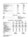
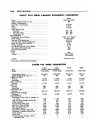
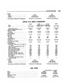
SPECIFICATIONS
14
37
63
64
G E N E R A L INFORMATION
SERVICING C A R B U R E T O R
D i r t , dust, w a t e r a n d g u m m y deposits a r e s o m e of
the m a i n causes f o r poor c a r b u r e t o r operation. H o w e v e r , p r o p e r c l e a n i n g a n d t h e i n s t a l l a t i o n of n e w
parts, w h e r e r e q u i r e d , w i l l r e t u r n t h e c a r b u r e t o r to
its o r i g i n a l d e s i g n e d p e r f o r m a n c e .
W h e n o v e r h a u l i n g the c a r b u r e t o r , s e v e r a l i t e m s of
i m p o r t a n c e s h o u l d be o b s e r v e d to a s s u r e a good j o b :
(1) A l l parts (except the c h o k e d i a p h r a g m a s s e m bly) s h o u l d be c a r e f u l l y c l e a n e d i n a suitable solvent,
then i n s p e c t e d f o r d a m a g e o r w e a r .
(2) U s e a i r p r e s s u r e only, to c l e a r t h e v a r i o u s orifices a n d c h a n n e l s .
(3) R e p l a c e questionable p a r t s w i t h N E W ones.
W h e n c h e c k i n g p a r t s r e m o v e d f r o m t h e c a r b u r e t o r , it
is at t i m e s r a t h e r difficult to be s u r e they a r e satisfactory f o r f u r t h e r s e r v i c e . It i s t h e r e f o r e , r e c o m m e n d e d that i n s u c h case, N E W p a r t s b e i n s t a l l e d .
(4) A l w a y s u s e a complete k i t w h e n o v e r h a u l i n g
the c a r b u r e t o r . U s i n g the code n u m b e r s t a m p e d on
the a i r h o r n , a d j a c e n t to the f u e l inlet, r e f e r to t h e
p a r t s catalog a n d o r d e r t h e c o r r e c t r e p a i r k i t f o r t h e
c a r b u r e t o r b e i n g w o r k e d on.
CLEANING CARBURETOR
PARTS
T h e r e c o m m e n d e d solvent f o r g u m deposits i s
d e n a t u r e d alcohol w h i c h i s e a s i l y obtainable. H o w e v e r , t h e r e a r e o t h e r c o m m e r c i a l solvents, ( s u c h as
Metalclene) w h i c h m a y b e u s e d w i t h s a t i s f a c t o r y r e sults.
T h e c h o k e d i a p h r a g m c a n be d a m a g e d b y solvents.
Avoid placing the diaphragm assembly in A N Y liquid.
C l e a n t h e e x t e r n a l s u r f a c e s w i t h a c l e a n c l o t h o r soft
w i r e b r u s h . S h a k e d i r t o r other f o r e i g n m a t e r i a l f r o m
the s t e m side of t h e d i a p h r a g m . D e p r e s s i n g t h e diap h r a g m s t e m to t h e r e t r a c t e d position, w i l l p r o v i d e a n
a d d i t i o n a l hole f o r t h e r e m o v a l of dirt. C o m p r e s s e d
a i r c a n b e u s e d to r e m o v e loose d i r t , but should not be
connected to the vacuum inlet fitting.
IMPORTANT: If the commercial solvent or cleaner
recommends the use of water as a rinse, it should be
"HOT"
After rinsing, all trace of water must be
blown from the passages with air pressure. It is
further advisable to rinse all parts in clean gasoline or
kerosene to be certain no trace of moisture remains.
Never clean jets with a wire, drill or other mechanical
means because the orifices may become enlarged,
making the fuel mixture too rich for proper performance.
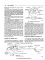
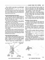
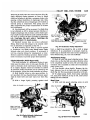
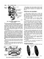
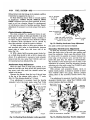
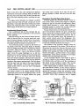
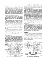
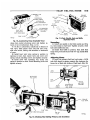
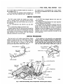
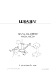
AUTOMATIC C H O K E (Well Type)
A n e w d e s i g n w e l l f o r t h e automatic c h o k e h a s b e e n
i n c o r p o r a t e d i n a l l e n g i n e s e x c e p t t h e 4 4 0 c u . i n . tricarb installation a n d the 426 c u . i n . H e m i . T h i s n e w
design allows f a s t e r o p e n i n g of t h e c h o k e m e c h a n i s m
r e s u l t i n g i n l e a n e r f u e l m i x t u r e s d u r i n g the w a r m - u p
period for reduced emissions and fuel consumption.
( F i g . 1).
T o f u n c t i o n p r o p e r l y , it i s i m p o r t a n t that a l l p a r t s
be c l e a n a n d m o v e f r e e l y . O t h e r t h a n a n o c c a s i o n a l
c l e a n i n g , the a u t o m a t i c
choke control requires no
s e r v i c i n g . H o w e v e r , it i s v e r y i m p o r t a n t that t h e c h o k e
control unit
works freely
at t h e t h e r m o s t a t i c
coil
s p r i n g h o u s i n g a n d at t h e c h o k e shaft. Move t h e c h o k e
r o d u p a n d d o w n to c h e c k f o r f r e e m o v e m e n t i n the
coil h o u s i n g . I f u n i t b i n d s , a n e w u n i t s h o u l d b e i n stalled. The well type choke is serviced as an assembly.
Do not attempt to repair or change the setting, unless
authorized by s e r v i c e l i t e r a t u r e . C h a n g e s of t h e c h o k e
setting materially
affect summer temperature
cold
starting and seldom are a satisfactory correction of
drive-ability problems, which are generally associated
with carburetors or vacuum diaphragms.
T w o types of w e l l s a r e i n g e n e r a l u s a g e . O n e i s cast
as a n i n t e g r a l p a r t of t h e m a n i f o l d . T h e s e c o n d i s a
PY138
Fig. I— Choke Control (Open Well) B-cy Under
Engine
14-2
F U E L SYSTEM-
stainless steel cup fastened over a p o r t i n the manifold (Fig. 1).
The stainless steel w e l l cups are held i n place by
choke retainer bolts. A steel-asbestos gasket seals the
exhaust gas w i t h i n the manifold. Loosening or removing the choke retainer bolts will allow exhaust gases
to escape into the engine compartment. DO NOT RUN
T H E ENGINE WITHOUT THE CHOKE FIRMLY
BOLTED T O T H E M A N I F O L D . FIRE OR H E A T D A M A G E M A Y OCCUR.
W h e n installing the steel w e l l cup, make certain the
gasket is i n good condition and is i n place to prevent
exhaust leakage.
Do not lubricate any of the choke parts or the cont r o l u n i t . This causes d i r t to accumulate, and w o u l d
result i n b i n d i n g of the choke mechanism.
The choke c o n t r o l u n i t is accurately adjusted when
first assembled. Under n o r m a l servicing do NOT
change the setting or disassemble the c o n t r o l u n i t .
I f however, t h e setting has been disturbed, reset as
follows: Loosen locknut and t u r n shaft w i t h screwd r i v e r u n t i l index m a r k on disc is i n alignment w i t h
correct m a r k o n the frame. H o l d i n this position w i t h
screwdriver while t i g h t e n i n g n u t , (Refer to Specifications f o r indexing).
A l l the carburetors referred t o i n the F u e l System
are either equipped f o r use w i t h a Cleaner A i r System
(C.A.S.) or an Evaporation Control System, (E.C.S.) depending on the area i n which the vehicle is t o be used.
The servicing procedures covering these carburetors
are nearly identical. Differences between the t w o
types of carburetors are covered (where applicable)
i n the service procedures.
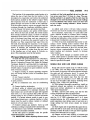
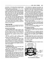
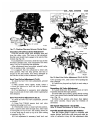
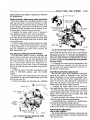
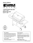
C L E A N E R AIR S Y S T E M (C.A.S.)
The cleaner air system consists of a special air
cleaner, breather cap, ventilation valve, carburetor,
distributor and various other automatic c o n t r o l de-
CARBURETOR
CRANKCASE
VENTILATION V A L V E
AIR CLEANER
BOWL VENT V A L V E
CLEANER
TO C A P HOSE
BREATHER C A P
VENT V A L V E
TO CARBURETOR HOSE
CRANKCASE
(VAPOR STORAGE AREA)
PY598
Fig. 2—Cleaner Air System (C.A.S.J
vices, (Fig. 2) as required.
The function of the cleaner air system is to reduce
the u n b u r n e d hydro-carbons emitted by t h e vehicle's
engine. Fresh a i r is d r a w n i n t o the a i r cleaner, f o r consumption by the engine. A p o r t i o n of this fresh a i r is
diverted t h r o u g h a hose to the breather cap and i n t o
the crankcase. Manifold vacuum causes crankcase
vapors (including fresh a i r and u n b u r n e d hydro-carbons) to flow t h r o u g h the crankcase ventilation valve
to t h e base (or t h r o t t l e body) of the carburetor. These
vapors are joined w i t h the f u e l m i x t u r e i n t h e intake
manifold and are delivered i n t o the combustion chamber, f r o m w h i c h they are ejected as essentially completely burned exhaust products.
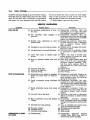
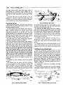
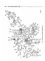
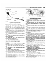
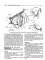
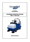
EVAPORATION CONTROL S Y S T E M (E.C.S.)
The evaporation c o n t r o l system consists of t h e
C.A.S. system plus, a special vented f u e l tank, separator, fuel tank vapor tube, breather cap, enclosed
b o w l vent valve, a vacuum pressure relief f u e l t a n k
cap and hoses (Fig. 3).
PY599
Fig. 3—Evaporation Control System
(EX.S.)
A
FUEL SYSTEM
14-3
T h e f u n c t i o n of the e v a p o r a t i o n c o n t r o l s y s t e m is to
r e d u c e the loss of f u e l f r o m t h e f u e l s y s t e m to t h e
atmosphere by evaporation and reduce the unburned
hydro-carbons e m i t t e d b y t h e v e h i c l e ' s engine. W h e n
f u e l evaporates f r o m t h e c a r b u r e t o r o r f u e l tank, it
passes through vent hoses o r tubes to t h e c r a n k c a s e .
With the engine running, vapors a r e purged from the
c r a n k c a s e t h r o u g h t h e c r a n k c a s e ventilation s y s t e m ,
as i n the C l e a n e r A i r S y s t e m p r e v i o u s l y d e s c r i b e d .
to obtain air/fuel rati© specified,'do not Turn
ture screw more than 1/16 turn at a time. The combustion analyzer is so sensitive that the ratio must be
changed in very small increments if accurate readings
are to be obtained. The meters read in air/fuel ratio
so that a higher reading indicates a leaner mixture
and vice versa.
T h e f u e l t a n k c o n t a i n s a one gallon overfill l i m i t e r
tank. W h e n t h e f u e l t a n k i s filled, t h e overfill l i m i t e r
tank r e m a i n s e s s e n t i a l l y e m p t y , to a l l o w f o r t h e r m a l
e x p a n s i o n . E a c h c o r n e r of t h e f u e l t a n k i s v e n t e d a n d
e a c h of the hoses f r o m these v e n t s a r e c o n n e c t e d to
the separator. A tube f r o m the s e p a r a t o r l e a d s to the
breather cap. T h u s evaporated fuel vapor from the
f u e l tank, flows t h r o u g h t h e s e p a r a t o r , to t h e engine
c r a n k c a s e a n d t h e n t h r o u g h t h e c r a n k c a s e ventilation
s y s t e m . I n addition, t h e c a r b u r e t o r f u e l bowl v e n t
valve i s also i n c l u d e d , b y a tube f r o m t h e v e n t v a l v e
to the b r e a t h e r c a p , o r f u e l p u m p . (6 C y l i n d e r e n gines.) T h i s c o m p l e t e l y seals the f u e l s y s t e m .
c l o c k w i s e ) a n d wait 10 seconds b e f o r e r e a d i n g m e t e r .
(b) I f n e c e s s a r y , r e p e a t step " a " u n t i l m e t e r i n d i cates a definite i n c r e a s e i n r i c h n e s s (lower r e a d i n g ) .
T h i s step i s v e r y i m p o r t a n t s i n c e m e t e r r e v e r s e s its
r e a d i n g s a n d i n d i c a t e s a r i c h e r m i x t u r e as c a r b u r e t o r
is l e a n e d out i f c a r b u r e t o r is set too l e a n .
Idle Speed
Adjustment
(Curb
Idle)
T o m a k e t h e idle s p e e d a d j u s t m e n t o n c a r b u r e t o r s ,
s e c u r e a n a c c u r a t e ignition
tachometer and a S u n
E l e c t r i c C o m b u s t i o n - V a c u u m U n i t , M o d e l 80, E x h a u s t
C o n d e n s e r , M o d e l E C , a n d H o s e 669-14 o r equivalent.
(a) A d j u s t e a c h s c r e w 1 / 1 6 t u r n r i c h e r (counter-
(c) W h e n it h a s b e e n e s t a b l i s h e d that m e t e r i s indic a t i n g a l o w e r r e a d i n g ( r i c h e r m i x t u r e ) w h e n idle
m i x t u r e s c r e w s a r e t u r n e d i n r i c h e r d i r e c t i o n , pro*
c e e d to a d j u s t c a r b u r e t o r to give 14.2 a i r / f u e l ratio,
t u r n i n g s c r e w s c o u n t e r c l o c k w i s e (richer) to l o w e r
m e t e r r e a d i n g a n d c l o c k w i s e (leaner) to i n c r e a s e
meter reading.
(d) I f idle s p e e d c h a n g e s as m i x t u r e s c r e w s a r e
t u r n e d , a d j u s t s p e e d to specified v a l u e a n d r e a d j u s t
m i x t u r e a s r e q u i r e d so that 14.2 a i r / f u e l ratio i s obt a i n e d at specified idle s p e e d .
ROUGH IDLE AND LOW S P E E D S U R G E
( T h e above a n a l y z e r i s r e c o m m e n d e d ; h o w e v e r , other
r e l i a b l e m a k e s of a n a l y z e r s i n good condition m a y b e
R o u g e i d l e a n d l o w s p e e d s u r g e on v e h i c l e s (using
1-1/2" BED, A V S , and Holley 4160 carburetors) may
used). P r o c e e d as follows:
(1) E n g i n e r u n n i n g at n o r m a l o p e r a t i n g t e m p e r a -
be t h e r e s u l t of i m p r o p e r idle setting b a l a n c e b e t w e e n
t u r e , a n d t i m i n g c h e c k e d , (refer to D i s t r i b u t o r S p e c i -
the r i g h t a n d left c a r b u r e t o r b o r e s . T o c o r r e c t this
fications).
condition t h e f o l l o w i n g steps s h o u l d b e followed.
(1) R e m o v e t h e plastic c a p s
(2) A i r C l e a n e r i n s t a l l e d .
(3) A u t o m a t i c t r a n s m i s s i o n s i n n e u t r a l position (not
from
t h e t w o idle
s c r e w s i n b a s e of c a r b u r e t o r ( 1 - 1 / 2 " B E D a n d A V S )
or c u p o r i n t h e sides i f t h e p r i m a r y m e t e r i n g b l o c k
i n p a r k position).
(4) O n a i r conditioned c a r s , t u r n a i r conditioning
off.
(Holley). (Figs. 1, B E D , A V S , a n d H o l l e y ) .
(2) W i t h e x h a u s t t h o r o u g h l y w a r m e d u p , i n s t a l l a n
(5) C o n n e c t ignition t a c h o m e t e r .
a p p r o v e d e x h a u s t gas a n a l y z e r f o r c a r b u r e t o r
(6) I n s e r t probe
speed and mixture
of e x h a u s t gas a n a l y z e r i n t a i l
pipe as f a r as possible (2 ft. m i n i m u m distance). O n
d u a l e x h a u s t c a r s u s e left side t a i l pipe (side opposite
h e a t valve). I t i s v e r y i m p o r t a n t that probe a n d con-
idle
adjustment as described under
"Idle Speed Adjustment".
(3) W i t h a n a r r o w s c r e w d r i v e r , t u r n t h e t w o idle
s c r e w s c l o c k w i s e u n t i l t h e y a r e both seated.
n e c t i n g t u b i n g be f r e e of l e a k s to p r e v e n t e r r o n e o u s
(4) T u r n both idle s c r e w s 1-1/2 t u r n s c o u n t e r c l o c k -
r e a d i n g . I f a g a r a g e e x h a u s t s y s t e m i s u s e d to con-
w i s e f o r 1 - 1 / 2 " B B D c a r b u r e t o r s a n d 2 to 3 t u r n s
d u c t e x h a u s t gases a w a y , a p l e n u m c h a m b e r o r other
counterclockwise for A V S carburetors as a starting
m e a n s m u s t b e u s e d to r e d u c e v a c u u m o r e x h a u s t
point ( e x p e r i e n c e m a y dictate m o r e o r less t u r n s a s a
s y s t e m to 1 / 2 i n c h w a t e r o r less.
rough
(7) C o n n e c t e x h a u s t gas a n a l y z e r , w a r m u p a n d
c a l i b r a t e a c c o r d i n g to m a n u f a c t u r e r ' s i n s t r u c t i o n s .
(8) D i s c o n n e c t h o s e b e t w e e n
distributor
vacuum
control valve and intake manifold.
(9) S e t i d l e s p e e d to specified v a l u e f o r specific
engine-transmission combination.
(10) I M P O R T A N T : When adjusting mixture screws
setting
b u t both
screws
should be
turned
equally).
(5) S t a r t e n g i n e a n d s e t specified idle s p e e d f o r e n gines w i t h 300 or more miles. Set 75 r p m below specifications
if u n d e r 50 m i l e s o r 50 r p m below specifica-
tions i f 50 to 300 m i l e s a r e on engine.
(6) O b s e r v e a i r / f u e l ratio r e a d i n g of e x h a u s t g a s
a n a l y z e r . T u r n e a c h s c r e w 1 / 1 6 t u r n r i c h e r (counter-
14-4
FUEL SYSTEM
A
c l o c k w i s e ) a n d note c h a n g e i n a i r / f u e l m e t e r r e a d i n g .
F r o m this point on, follow i n s t r u c t i o n s f o r idle setting
u n t i l 14.2 a i r / f u e l ratio i s obtained at a p p r o x i m a t e
idle s p e e d . It is v e r y i m p o r t a n t that both i d l e l i m i t e r
s c r e w s be t u r n e d the s a m e a m o u n t on e a c h a d j u s t m e n t so that as finally set both s c r e w s w i l l be the
s a m e n u m b e r of t u r n s f r o m the s e a t e d position.
(7) I n s t a l l p l a s t i c c a p s o v e r i d l e s c r e w s .
SERVICE DIAGNOSIS
Condition
Possible Cause
Correction
POOR IOLING
(a) Idle a i r bleed c a r b o n i z e d or of incor- (a) D i s a s s e m b l e carburetor. T h e n , u s e
c o m p r e s s e d air to c l e a r idle bleed
rect s i z e .
after s o a k i n g it in a suitable solvent.
(b) Idle d i s c h a r g e holes plugged or (b) D i s a s s e m b l e carburetor. T h e n , u s e
c o m p r e s s e d air to c l e a r idle d i s c h a r g e
gummed.
holes after s o a k i n g main a n d throttle
bodies in a suitable solvent.
(c) Throttle body c a r b o n i z e d or worn (c) D i s a s s e m b l e carburetor. C h e c k throttle valve shaft for wear. If e x c e s s i v e
throttle shaft.
wear is apparent, r e p l a c e throttle
body a s s e m b l y .
(d) D a m a g e d or worn idle mixture needle. (d) R e p l a c e worn or d a m a g e d idle needle.
Adjust air mixture.
(e) Low grade fuel or incorrect float level. (e) T e s t fuel level in carburetor. A d j u s t
a s n e c e s s a r y to obtain correct float
level.
(f) L o o s e m a i n body to throttle body (f) Tighten main body to throttle body
screws.
s c r e w s s e c u r e l y to prevent air l e a k s
a n d c r a c k e d housings.
(g) Worn or corroded needle valve a n d (g) C l e a n and i n s p e c t needle valve a n d
seat.
seat. If found to be in questionable
condition, replace a s s e m b l y . T h e n ,
test fuel pump p r e s s u r e . Refer to
S p e c i f i c a t i o n s for correct fuel p u m p
pressure.
(h) Incorrect valve lash.
(h) Adjust valves.
(i) E n g i n e m i s s (ignition),
(i) C h e c k ignition s y s t e m ,
(j) Incorrect timing.
(j) R e s e t timing.
POOR A C C E L E R A T I O N
(a) A c c e l e r a t o r p u m p piston (or plunger) (a) D i s a s s e m b l e carburetor. R e p l a c e a c leather too hard, worn, or loose on
celerator pump a s s e m b l y if leather i s
stem.
hard, c r a c k e d or worn. T e s t follow-up
s p r i n g for c o m p r e s s i o n .
(b) Faulty a c c e l e r a t o r pump d i s c h a r g e (b) D i s a s s e m b l e carburetor. U s e c o m ball.
p r e s s e d air to c l e a n d i s c h a r g e nozzle
a n d c h a n n e l s after s o a k i n g m a i n body
in a suitable solvent. T e s t a c c e l e r a t o r
pump capacity.
(c) Faulty a c c e l e r a t o r p u m p inlet c h e c k (c) D i s a s s e m b l e carburetor. C h e c k a c ball.
celerator pump inlet c h e c k ball for
poor s e a t or release. If part is faulty,
replace.
(d) Incorrect fuel or float level.
(d) T e s t fuel or float level in carburetor.
A d j u s t a s n e c e s s a r y to obtain c o r r e c t
float level.
(e) Worn a c c e l e r a t o r p u m p a n d throttle (e) D i s a s s e m b l e
carburetor.
Replace
linkage.
worn a c c e l e r a t o r pump a n d throttle
linkage and m e a s u r e for c o r r e c t position.
(f) Manifold heat valve s t i c k i n g .
(f) F r e e up manifold heat control valve;
u s i n g r e c o m m e n d e d solvent.
(g) No power mixture.
(g) T e s t power piston operation.
(h) I n c o r r e c t timing.
(h) R e s e t timing.
(i) Incorrect p u m p setting.
(i) R e s e t pump.
CARBURETOR FLOODS
OR L E A K S
(a) C r a c k e d body.
(a) D i s a s s e m b l e
carburetor.
Replace
c r a c k e d body. Make s u r e main to
throttle body s c r e w s are t i g h t
Condition
(b) Faulty body g a s k e t s .
(c) High float level.
(d) Worn needle valve a n d s e a t .
(e) E x c e s s i v e fuel p u m p p r e s s u r e .
POOR P E R F O R M A N C E
MIXTURE TOO RICH
(a) Restricted air c l e a n e r .
(b) L e a k i n g float.
(c) High float level.
(d) E x c e s s i v e fuel p u m p p r e s s u r e .
(e) Worn metering jet.
POOR C O L D E N G I N E
STARTING INCORRECT
PROCEDURE
CHOKE VALVE FAILS
TO C L O S E
LOW E N G I N E O U T P U T
(10°F or lower)
Correction
Possible Cause
(b) D i s a s s e m b l e carburetor. R e p l a c e d e fective g a s k e t s a n d t e s t for leakage.
Be s u r e s c r e w s a r e tightened s e curely.
(c) T e s t fuel level in carburetor. Make
n e c e s s a r y a d j u s t m e n t to obtain correct float level.
(d) C l e a n and i n s p e c t n e e d l e valve a n d
seat: If found to be in a questionable
condition, r e p l a c e c o m p l e t e a s s e m b l y
and test fuel pump p r e s s u r e . R e f e r
to S p e c i f i c a t i o n s for c o r r e c t fuel
pump p r e s s u r e .
(e) T e s t fuel pump p r e s s u r e . If p r e s s u r e
is in e x c e s s of r e c o m m e n d e d p r e s s u r e (refer to S p e c i f i c a t i o n s ) , r e p l a c e
fuel pump.
(a) Remove and c l e a n air c l e a n e r .
(b) D i s a s s e m b l e
carburetor.
Replace
leaking float. T e s t float level a n d cor
rect a s n e c e s s a r y , to proper level.
(c) A d j u s t float level a s n e c e s s a r y to s e
c u r e proper level.
(d) T e s t fuel pump p r e s s u r e . R e f e r to
specifications for r e c o m m e n d e d press u r e . If p r e s s u r e is in e x c e s s of r e c ommended
pressure, replace
fuel
pump a s s e m b l y .
(e) D i s a s s e m b l e
carburetor.
Replace
worn metering jet, u s i n g a new jet of
correct s i z e a n d type.
(a) ( S e e owner's Manual.)
(a) Instruct owner.
(a) Choke thermostat a d j u s t m e n t leaner
than s p e c i f i e d .
(b) C h o k e thermostat corroded s u c h that
it h a s c r a c k e d and distorted lean.
(c) Choke linkage, shaft or related parts
corroded, bent or dirty s u c h that s y s tem is not entirely free to move from
open to c l o s e d position.
(d) Choke valve improperly s e a t e d .
(e) Air c l e a n e r interfers with c h o k e s h a f t
or linkage.
(f) Air c l e a n e r g a s k e t interfers with
choke valve or linkage.
(g) S p r i n g staging s p r i n g distorted or
missing.
(a) Adjust,
(b) R e p l a c e a s s e m b l y ,
(c) Repair, c l e a n or r e p l a c e ,
(d) R e s e a t valve.
(e) Rotate c l e a n e r to c o r r e c t
instruct owner,
(f) Reinstall g a s k e t properly.
position,
(g) R e p l a c e or install new spring,
(a) Engine lubricating oil incorrect v i s - (a) R e c o m m e n d 5W-20.
cosity.
(b) C h o k e thermostat a d j u s t m e n t incor- (b) A d j u s t to c o r r e c t setting,
rect, r i c h .
ENGINE RUNS LEAN, FIRST HALF MILE
CHOKE LEAN
(a) Review items under (Poor Starting).
(b) Diaphragm a d j u s t m e n t lean.
(a) S e e " C h o k e Valve F a i l s to C l o s e . "
(b) R e a d j u s t to s p e c i f i c a t i o n .
ENGINE RUNS LEAN AFTER HALF MILE
ENGINE HEAT
INSUFFICIENT
(a) Heat valve s t u c k o p e n .
(b) Heat valve thermostat distorted.
(a) F r e e with solvent.
(b) R e p l a c e thermostat.
14-6
FUEL SYSTEM—BBDCondition
Possible Cause
Correction
(c) Heat valve failed within e x h a u s t S e e (c) R e p l a c e h e a t valve.
engine s e c t i o n for proper diagnosis.
(d) C h e c k thermostat.
(d) Water temperature s u b n o r m a l .
CARBURETOR
MIXTURES LEAN
(a) Repair.
(a) Air leak b y p a s s i n g the carburetor.
(b) Carburetor h a s e c o n o m y
metering (b) Inform c u s t o m e r .
system.
ENGINE RUNS E X C E S S I V E L Y RICH AFTER COLD START
CHOKE S Y S T E M RICH
(a) C h o k e thermostat a d j u s t m e n t richer (a) Correct.
than s p e c i f i e d .
(b) C h o k e v a c u u m diaphragm inoperative (b) Correct or r e p l a c e .
or m i s a d j u s t e d .
(c) Choke v a c u u m p a s s a g e blocked or (c) Correct.
leaking.
CARBURETOR RICH
(a) Incorrect g a s k e t or g a s k e t installation (a) R e p l a c e or correct.
between carburetor a n d intake m a n i fold.
E X C E S S I V E S T A L L S AFTER COLD START
CHOKE S Y S T E M LEAN
ENGINE OUTPUT LOW
CARBURETOR LEAN
(a) Review i t e m s under "Poor StartingC h o k e Valve F a i l s to C l o s e . "
(b) C h o k e v a c u u m diaphragm a d j u s t m e n t (b) Adjust to S p e c i f i c a t i o n ,
lean.
(a) F a s t idle s p e e d low.
(b) F a s t idle c a m position a d j u s t m e n t
incorrect.
(c) E n g i n e lubrication oil of incorrect
viscosity.
(d) Incorrect timing.
(a) A d j u s t to S p e c i f i c a t i o n .
(b) Adjust to S p e c i f i c a t i o n ,
(a) C u r b idle s e t very lean.
(b) Air leak b y p a s s i n g the carburetor.
(a) Adjust.
(b) Repair.
BBD SERIES CARBURETORS
(c) R e c o m m e n d e d 5W-20.
(d) R e s e t timing.
(W*)
INDEX
Automatic C h o k e (well type)
Carburetor A d j u s t m e n t s
Accelerator P u m p a n d Bowl Vent
C h o k e U n l o a d e r (Wide O p e n K i c k )
Choke Vacuum Kick
F a s t Idle C a m Position .
F a s t Idle S p e e d (On V e h i c l e )
Page
1
......
11
11-13
12
12
11
14
Page
Idle S p e e d A d j u s t m e n t
13
C l e a n i n g Carburetor Parts
1
C l o s e d C r a n k c a s e Vent S y s t e m . . . ( E n g i n e Group)
D i s a s s e m b l i n g Carburetor
7
Inspection and R e a s s e m b l y
9
Specifications . . . .
65
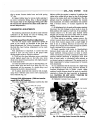
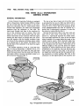
G E N E R A L INFORMATION
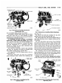
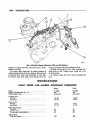
T h e B a l l a n d B a l l d u a l throat 1-1/2 i n c h C a r b u r e t o r
Model C.A.S. (Cleaner A i r System) B B D - 4 7 2 5 S , B B D 4 7 2 6 S a n d B B D - 4 8 9 4 S a r e u s e d o n t h e 383 c u . i n . E n gines w h e n t h e v e h i c l e s a r e e q u i p p e d w i t h m a n u a l o r
automatic t r a n s m i s s i o n s r e s p e c t i v e l y ( F i g . 1). B B D 4 7 2 6 S i s u s e d only o n v e h i c l e s without a i r conditioni n g w h i l e B B D - 4 8 9 4 S i s u s e d only on v e h i c l e s w i t h a i r
conditioning. T h i s c a r b u r e t o r i s e q u i p p e d w i t h a h o t
idle compensator valve, which is a thermostatically
o p e r a t e d a i r b l e e d , to r e l i e v e a n o v e r r i c h condition a t
idle. T h i s condition i s the r e s u l t of e x c e s s i v e h e a t a n d
resultant overrich mixtures. These three carburetors
a r e also e q u i p p e d w i t h a distributor g r o u n d s w i t c h ,
w h i c h r e t a r d s t h e distributor w h e n t h e c a r b u r e t o r i s
at c u r b i d l e , f o r better e m i s s i o n c o n t r o l .
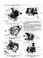
T h e B a l l a n d B a l l d u a l throat 1-1/2 i n c h c a r b u r e t o r
models E . C . S . (Evaporation Control System) B B D 4727S and BBD-4728S are used on the 383 cu. i n . engines when the vehicles a r e equipped with manual
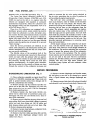
a n d automatic t r a n s m i s s i o n s r e s p e c t i v e l y ( F i g . 2). B o t h
A
BBD—FUEL SYSTEM
of these c a r b u r e t o r s are e q u i p p e d w i t h a hot idle c o m pensator v a l v e w h i c h is a t h e r m o s t a t i c a l l y o p e r a t e d
a i r b l e e d to r e l i e v e a n o v e r r i c h c o n d i t i o n at idle. T h i s
condition i s the r e s u l t of e x c e s s i v e h e a t a n d r e s u l t a n t
o v e r r i c h m i x t u r e s . T h e s e two c a r b u r e t o r s are also
e q u i p p e d w i t h a distributor g r o u n d s w i t c h , w h i c h r e tards the distributor w h e n the c a r b u r e t o r is at c u r b
idle, for better e m i s s i o n control.
S i n c e the s e r v i c e p r o c e d u r e s a r e i d e n t i c a l o n a l l
B B D c a r b u r e t o r s , the illustrations s h o w i n g the v a r i ous d i s a s s e m b l y p r o c e d u r e s w i l l not a l w a y s s h o w a n y
one specific c a r b u r e t o r .
14-7
T h e B a l l and
B a l T m ^ d o w n d r a f t type. E a c h throat h a s its o w n throttle v a l v e , a n d
m a i n m e t e r i n g s y s t e m s a n d a r e s u p p l e m e n t e d b y the
float, a c c e l e r a t i n g , i d l e a n d p o w e r s y s t e m s .
O n each B B D series carburetor, the model number
is s t a m p e d on m e t a l tag a t t a c h e d to a i r h o r n . D o not
r e m o v e or destroy t h i s tag, as it i s the only m e a n s
p r o v i d e d for c a r b u r e t o r m o d e l identification. B e f o r e
attempting to r e p a i r or o v e r h a u l c a r b u r e t o r , r e f e r to
m o d e l n u m b e r a n d s e c u r e a r e p a i r k i t for n u m b e r
i n d i c a t e d on tag.
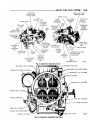
SERVICE PROCEDURES
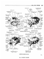
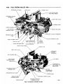
DISASSEMBLING CARBURETOR (Figs. 1 or 2.)
(1) I n s e r t three T o o l T-109-287S a n d one T o o l T 109-288S elevating legs t h r o u g h c a r b u r e t o r throttle
body s t u d holes. (These tools a r e u s e d to protect
throttle v a l v e s f r o m damage a n d to p r o v i d e a suitable
base for working.)
(2) R e m o v e h a i r p i n clip a n d d i s e n g a g e fast idle
c o n n e c t o r r o d f r o m fast idle c a m a n d c h o k e l e v e r .
(3) R e m o v e h a i r p i n clip a n d d i s e n g a g e a c c e l e r a t o r
rod f r o m throttle l e v e r a n d p u m p r o c k e r a r m .
(4) R e m o v e v a c u u m hose b e t w e e n c a r b u r e t o r throt-
tle body fitting a n d v a c u u m d i a p h r a g m .
(5) R e m o v e clip f r o m c h o k e o p e r a t i n g l i n k a n d disengage l i n k f r o m d i a p h r a g m p l u n g e r a n d c h o k e l e v e r .
(Figs. 1 or 2).
(6) R e m o v e v a c u u m d i a p h r a g m a n d b r a c k e t a s s e m bly a n d place to one side, to be c l e a n e d as a s p e c i a l
i t e m . A liquid cleaner m a y d a m a g e the d i a p h r a g m
material.
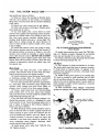
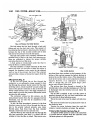
(7) R e m o v e s c r e w s t h a t attach hot idle compensator
v a l v e c o v e r to m a i n body. R e m o v e c o v e r a n d lift out
hot idle c o m p e n s a t o r v a l v e a n d g a s k e t ( F i g . 3).
(8) R e m o v e a i r h o r n r e t a i n i n g s c r e w s a n d lift a i r
ACCELERATOR PUMP
ROCKER ARM
ACCELERATOR
BOWL VENT
VALVE
P
U
M
DISTRIBUTOR G R O U N D
SWITCH TERMINAL
P
CHOKE LEVER
CHOKE
AIR
HORN
FAST IDLE
C O N N E C T O R ROD
CHOKE VALVE
OPERATING
LINK
DIAPHRAGM
STEM
CURB IDLE SPEED
ADJUSTING SCREW
CHOKE VACUUM
DIAPHRAGM
FUEL INLET
NEEDLE, VALVE,
SEAT
f
A N D GASKET f
CHOKE V A C U U M '
HOSE
'
MAIN
BODY
t
FAST IDLE
CAM
IDLE LIMITER CAP (2)
(IDLE MIXTURE ADJUSTING
SCREWS 2)
* *
^
THROTTLE LEVER
UNLOADER
ACCELERATOR
ROD
TANG
CLOSED CRANKCASE
VENT TUBE FITTING
IDLE LIMITER CAP (2)
(IDLE MIXTURE ADJUSTING
SCREWS 2)
DISTRIBUTOR VACUUM
A D V A N C E TUBE FITTING
PUMP
F i g . f - C a r b u r e t o r Assembly
PY498
(BBB-1-1/2 inch) C.A.S.
14-8
FUEL SYSTEM—BBD
CHOKE VALVE
FAST IDLE SPEED
ADJUSTING SCREW
•A
BOWL VENT
VALVE COVER
ACCELERATOR PUMP
ROCKER ARM
CHOKE OPERATING
LINK
CHOKE VALVE
BOWL VENT
VALVE VENT
TUBE FITTING
ACCELERATOR PUMP
ARM
BOWL VENT
VALVE COVER
FAST IDLE
C O N N E C T O R ROD
BOWL VENT VALVE
VENT TUBE
DISTRIBUTOR
^
AIR HORN
CHOKE LEVER
/
CURB IDLE
SPEED
ADJUSTING
SCREW
ground
MAIN BODY
FUEL INLET—""*""'*
NEEDLE, VALVE, SEAT
AND GASKET
AIR CLEANER T O
CARBURETOR
VACUUM
TUBE FITTING
CLOSED CRANKCASE
VENT TUBE
FITTING
SWITCH
j ; TERMINAL
FAST IDLE
CAM
IDLE LIMITER CAP (2)
(IDLE MIXTURE ADJUSTING
SCREWS 2)
DISTRIBUTOR VACUUM
A D V A N C E TUBE FITTING
THROTTLE BODY
CHOKE VACUUM
DIAPHRAGM
Fig. 2—Carburetor Asset
THROTTLE LEVER
UNLOADER T A N G
ACCELERATOR PUMP
ROD
PY499
y (BBD 1-1/2 inch) F.C.S.
h o r n s t r a i g h t u p a n d a w a y f r o m m a i n body. D i s c a r d
gasket (2 s c r e w s r e c e s s e d ) .
(9) D i s e n g a g e a c c e l e r a t o r p u m p p l u n g e r f r o m a c c e l e r a t o r p u m p a r m b y p u s h i n g u p o n bottom of
p l u n g e r a n d s l i d i n g p l u n g e r s h a f t off hook. S l i d e
p l u n g e r out of a i r h o r n a n d r e m o v e c o m p r e s s i o n
s p r i n g a n d seat. R e m o v e b o w l v e n t v a l v e cover.
g a s o l i n e o r k e r o s e n e to p r e v e n t l e a t h e r f r o m d r y i n g
If o l d p l u n g e r c a n b e u s e d a g a i n o r i f a n e w p l u n g e r i s to b e i n s t a l l e d , p l a c e p l u n g e r i n a j a r of c l e a n
a n d s l i d e step-up piston a n d r o d s out of w e l l , ( F i g . 4).
out.
(10) R e m o v e f u e l i n l e t n e e d l e v a l v e , seat a n d gasket
f r o m m a i n body.
(11) L i f t out float f u l c r u m p i n r e t a i n e r , a n d lift out
floats a n d f u l c r u m p i n .
(12) R e m o v e step-up piston a n d r e t a i n i n g
screw
L i f t out step-up piston s p r i n g . R e m o v e step-up p i s t o n
g a s k e t f r o m bottom of w e l l .
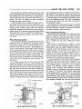
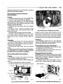
(13) R e m o v e m a i n m e t e r i n g j e t s ( F i g . 5).
(14) R e m o v e v e n t u r i c l u s t e r s c r e w s , t h e n lift v e n t u r i c l u s t e r a n d gaskets u p a n d a w a y f r o m m a i n body,
( F i g . 6). D i s c a r d gaskets. Do not remove idle orifice
PY500
Fig. 3—Removing or Installing Hot Idle
Compensator
Valve
Fig. 4—Removing or Installing Step-Up
Piston
-BBD—FUEL SYSTEM
A-
VENTURI CLUSTER
SCREWS
14-9
VENTURICtOSTER
CAP
-VENTURI CLUSTER
SPECIAL TOO!,
3»r
GASKET
it-tj
MAIN -~METERING JETS
ACCELERATOR
PUMP DISCHARGE
GASKET
NR380A
Fig. 5—Removing o r installing Main Metering
Jets
tubes o r m a i n vent tubes from cluster. T h e y c a n b e
c l e a n e d i n a solvent a n d d r i e d w i t h c o m p r e s s e d a i r .
(15) I n v e r t c a r b u r e t o r a n d d r o p out a c c e l e r a t o r
pump discharge check ball a n d intake check ball.
( T h e intake c h e c k b a l l i s t h e largest.)
(16) R e m o v e s c r e w s that a t t a c h throttle body to
m a i n body. S e p a r a t e the bodies a n d d i s c a r d g a s k e t .
(17) R e m o v e p l a s t i c l i m i t e r c a p s f r o m idle a i r mixture s c r e w s . ( B e s u r e a n d c o u n t n u m b e r of t u r n s to
seat the s c r e w s , as t h e s a m e n u m b e r of t u r n s (from
the seat) m u s t be m a i n t a i n e d at installation.) R e m o v e
s c r e w s a n d s p r i n g s f r o m throttle body.
T h e c a r b u r e t o r n o w h a s b e e n d i s a s s e m b l e d into
three sub-assemblies, t h e a i r h o r n , m a i n body a n d
throttle body a n d t h e c o m p o n e n t s of e a c h d i s a s s e m bled as f a r as n e c e s s a r y f o r c l e a n i n g a n d i n s p e c t i o n .
ACCELERATOR
PUMP DISCHARGE
CHECK BALL
NR381
Fig. 6—Removing or Installing Venturi
Cluster
v a l v e s i s to be i n s t a l l e d , a d h e r e to t h e f o l l o w i n g i n structions:
(2) M a r k position of throttle v a l v e s i n b o r e s .
(3) R e m o v e s c r e w s that h o l d throttle v a l v e s to shaft
and
s l i d e v a l v e s out of b o r e s . These
screws
are
staked on the opposite side and care should be used at
removal so as not to break off in the shaft.
R e m o v e t h e s t a k e d e n d of t h e s c r e w s w i t h a file.
(4) S l i d e t h r o t t l e s h a f t a n d l e v e r out of body.
(5) I n s t a l l n e w throttle shaft a n d l e v e r .
(6) I n s t a l l t h r o t t l e v a l v e s i n t h e i r r e s p e c t i v e b o r e s
(with v a l v e n u m b e r s t o w a r d manifold). I n s t a l l n e w
s c r e w s b u t do not tighten. H o l d v a l v e s i n p l a c e (fully
It i s u s u a l l y not advisable to r e m o v e t h e throttle
shaft or v a l v e s f r o m the throttle body, u n l e s s w e a r o r
damage necessitates t h e i n s t a l l a t i o n of n e w p a r t s .
of v a l v e s . T a p v a l v e s l i g h t l y w i t h a s c r e w d r i v e r to seat
T h e r e is about .005 i n c h c l e a r a n c e b e t w e e n t h e
throttle shaft a n d t h e throttle shaft b o r e s i n t h e throttle body. A n y c l e a r a n c e o v e r .010 i n c h , a n e w throttle
shaft a n d / o r throttle body s h o u l d b e i n s t a l l e d .
( T h e y m a y h a v e to be r o t a t e d slightly as t h e v a l v e s a r e
INSPECTION AND
Throttle
c l o s e d position) w i t h
fingers
p r e s s i n g on h i g h sides
i n throttle b o r e s . P a r t i a l l y tighten s c r e w s . H o l d u p to
a s t r o n g light to c h e c k f o r a p r o p e r position i n b o r e .
eliptical.) W h e n p r o p e r l y positioned tighten
screws
securely and stake, using pliers.
(7) I n s t a l l i d l e m i x t u r e s c r e w s a n d s p r i n g s i n body.
REASSEMBLY,.
Body
( T h e t a p e r e d p o r t i o n m u s t be straight a n d s m o o t h . I f
t a p e r e d portion i s g r o o v e d o r r i d g e d , a n e w idle mixt u r e s c r e w s h o u l d b e i n s t a l l e d to i n s u r e h a v i n g cor-
(1) I n s p e c t t h e throttle shaft a n d throttle body f o r
r e c t i d l e m i x t u r e control.) DO NOT U S E A S C R E W
e x c e s s i v e w e a r . I f e i t h e r o r both a r e w o r n to t h e point
D R I V E R . T u r n s c r e w s lightly against t h e i r seats w i t h
w h e r e the c a r b u r e t o r operation w i l l be affected, r e place as r e q u i r e d .
D u r i n g m a n u f a c t u r e , t h e location of the i d l e t r a n s f e r port a n d the s p a r k a d v a n c e c o n t r o l ports to t h e
throttle v a l v e , i s c a r e f u l l y e s t a b l i s h e d f o r one p a r t i c u l a r a s s e m b l y , ( F i g . 7).
If a n e w shaft s h o u l d be i n s t a l l e d i n a n o l d , w o r n
IDLE
TRANSFER PORTS
r- -
•/
SPARK
ADVANCE
V
PORT
w •
\
throttle body, it w o u l d be v e r y u n l i k e l y that t h e origin a l r e l a t i o n s h i p of t h e ports to t h e v a l v e s w o u l d b e
obtained. C h a n g i n g t h e r e l a t i o n s h i p of t h e v a l v e s to
the ports w o u l d a d v e r s e l y affect n o r m a l c a r operation
b e t w e e n the s p e e d s of 15 a n d 30 m i l e s p e r h o u r . I f it
h a s b e e n d e t e r m i n e d , h o w e v e r , t h a t a n e w shaft o r
0
:
' THROTTLE VAIVFS
Fig. 7—Ports in Relation to Throttle
!
NR3B2
Valves
fingers. B a c k off the n u m b e r of t u r n s c o u n t e d at disa s s e m b l y . I n s t a l l n e w p l a s t i c c a p s w i t h tabs against
stop. This s c r e w has a left h a n d t h r e a d . T u r n counterc l o c k w i s e ( R i c h e r ) a n d c l o c k w i s e (Leaner).
Main
Body
(1) I n v e r t m a i n body a n d p l a c e a n e w g a s k e t i n
position a n d place throttle body o n m a i n body a n d
align. I n s t a l l s c r e w s a n d tighten s e c u r e l y .
(2) I n s t a l l a c c e l e r a t o r p u m p d i s c h a r g e c h e c k b a l l i n
d i s c h a r g e passage a n d c h e c k a c c e l e r a t o r p u m p syst e m ; f u e l i n l e t a n d d i s c h a r g e c h e c k b a l l s as follows:
(3) P o u r c l e a n gasoline into c a r b u r e t o r b o w l , approximately 1/2 i n c h deep. Remove pump plunger
f r o m j a r of gasoline, flex l e a t h e r s e v e r a l t i m e s , t h e n
s l i d e d o w n into p u m p c y l i n d e r . R a i s e p l u n g e r a n d
p r e s s lightly on p l u n g e r s h a f t to e x p e l a l l a i r f r o m
p u m p passage.
(4) U s i n g a s m a l l c l e a n b r a s s r o d , h o l d d i s c h a r g e
c h e c k b a l l d o w n firmly o n its seat. A g a i n r a i s e p l u n g e r a n d p r e s s d o w n w a r d . N o f u e l s h o u l d be e m i t t e d
f r o m e i t h e r i n t a k e o r d i s c h a r g e passage, ( F i g . 8).
If a n y f u e l does e m i t f r o m e i t h e r passage, it indicates the p r e s e n c e of d i r t or a d a m a g e d c h e c k b a l l
seat. C h e c k the p a s s a g e a g a i n a n d r e p e a t test. If l e a k age i s s t i l l e v i d e n t , i n s t a l l a n e w c h e c k b a l l . T h e f u e l
i n l e t c h e c k b a l l is l o c a t e d at the bottom of the p l u n g e r
well.
(5) I n s t a l l n e w g a s k e t s o n v e n t u r i c l u s t e r , a n d i n s t a l l i n position i n m a i n body. I n s t a l l c l u s t e r s c r e w s
a n d tighten s e c u r e l y . T e s t p u m p d i s c h a r g e b y p r e s s i n g p u m p p l u n g e r d o w n . T w o fine s t r e a m s of f u e l
s h o u l d be f o r c e d f r o m c l u s t e r . I f e i t h e r s t r e a m i s
r e s t r i c t e d or d i v e r t e d , r e m o v e c l u s t e r a n d r e c l e a n .
A f t e r test, p o u r f u e l f r o m the b o w l a n d r e m o v e p u m p
plunger.
(6) I n s t a l l m a i n m e t e r i n g
(Fig.
;
FUEL SYSTEM—BUD*
14-10
jets. Tighten securely.
5).
,
(7) B e f o r e i n s t a l l i n g step-up p i s t o n , be s u r e step-up
r o d s a r e able to m o v e f r e e l y , e a c h side of the v e r t i c a l
position, ( F i g . 9). ( T h e step-up r o d s m u s t be straight,
smooth a n d f r e e to m o v e f o r w a r d a n d b a c k w a r d f r o m
vertical.)
(8) S l i d e step-piston g a s k e t d o w n into position i n
piston w e l l , t h e n i n s t a l l the step-up piston s p r i n g ,
step-up piston a n d r o d s . C a r e f u l l y g u i d e step-up r o d s
into m a i n m e t e r i n g j e t s ( F i g . 4). I n s t a l l r e t a i n i n g
s c r e w a n d tighten s e c u r e l y . C h e c k piston for f r e e
operation i n w e l l .
A step-up piston s t u c k i n the Up position w i l l c a u s e
a r i c h m i x t u r e at p a r t throttle, w h e r e a s a piston s t u c k
i n the Down position w i l l c a u s e a l e a n m i x t u r e at w i d e
open throttle a n d poor a c c e l e r a t i o n .
Measuring
Float
Setting
The carburetors are equipped with a rubber-tipped
f u e l inlet n e e d l e . T h e r u b b e r tip i s flexible e n o u g h to
m a k e a good s e a l on the n e e d l e seat, a n d to give
i n c r e a s e d r e s i s t a n c e to flooding. C a r e s h o u l d be t a k e n
to p e r f o r m this operation a c c u r a t e l y i n o r d e r to s e c u r e the best p e r f o r m a n c e a n d f u e l e c o n o m y .
(1) T o c o r r e c t l y set float h e i g h t w h e n c a r b u r e t o r i s
b e i n g o v e r h a u l e d , i n s t a l l floats w i t h f u l c r u m p i n a n d
p i n r e t a i n e r i n m a i n body.
(2) I n s t a l l r u b b e r - t i p p e d n e e d l e , seat a n d g a s k e t i n
body a n d tighten s e c u r e l y .
(3) I n v e r t m a i n body so that w e i g h t of float only
is f o r c i n g n e e d l e against seat. H o l d finger against ret a i n e r to f u l l y seat f u l c r u m p i n .
(4) U s i n g T o o l T-109-280 o r a " T " s c a l e , m e a s u r e
float, (Fig. 10). T h e r e s h o u l d be 5 / 1 6 i n c h f r o m s u r f a c e
of f u e l b o w l to c r o w n of e a c h float at c e n t e r .
I f a n a d j u s t m e n t i s n e c e s s a r y , h o l d the floats on
bottom of the b o w l a n d b e n d float lip t o w a r d o r a w a y
f r o m n e e d l e . R e c h e c k the 5 / 1 6 i n c h setting a g a i n a n d
r e p e a t the lip b e n d i n g operation as r e q u i r e d .
C A U T I O N : W h e n bending the float lip, do not allow
the lip to push against the needle as the synethetic
rubber tip can be compressed sufficiently to cause a
false setting which will affect correct level of fuel in
the bowl.
STEP-UP RODS
MUST MOVE
FREELY
Fig. 3—Testing Accelerator Pump Intake and
Discharge Check Balls
A
NK617
Fig. 9—Step-Up Rods Freeplay
BBD—FUEL SYSTEM
A
FULCRUM PIN
14-11
I n s t a l l t h e d i a p h r a g m a s s e m b l y on t h e ^ h o f n ~ a s
follows:
(1) A s s e m b l e d i a p h r a g m to a i r h o r n a n d tighten
attaching screws securely.
RETAINER IN
POSITION
(2) I n s t a l l c h o k e operating l i n k i n p o s i t i o n b e t w e e n
d i a p h r a g m p l u n g e r (stem) a n d c h o k e l e v e r . I n s t a l l
c l i p to s e c u r e .
R OAT GAUGF
NR384
ONLY WEIGHT OF FLOATS
INLET NEEDLE
AGAINST
Fig. I0—Checking Float
Setting
(3) I n s p e c t r u b b e r hose f o r c r a c k s b e f o r e p l a c i n g i t
on c o r r e c t c a r b u r e t o r fitting. ( F i g . 1). D o n o t c o n n e c t
v a c u u m h o s e to d i a p h r a g m fitting u n t i l after v a c u u m
k i c k a d j u s t m e n t h a s b e e n m a d e . (See C a r b u r e t o r A d justments.)
CARBURETOR
ADJUSTMENTS
A f t e r being c o m p r e s s e d , t h e tip i s v e r y slow to r e c o v e r its o r i g i n a l s h a p e .
C A U T I O N : It is very important that the float lip be
perpendicular to the needle or slanted not more than
ten degrees away from the needle when the float
height is correct.
Air
Horn
(1) T e s t f r e e n e s s of c h o k e m e c h a n i s m i n a i r h o r n .
T h e c h o k e shaft m u s t float f r e e to operate c o r r e c t l y .
If choke shaft sticks i n b e a r i n g a r e a s , o r a p p e a r s
to be g u m m e d f r o m deposits i n a i r h o r n , a t h o r o u g h
c l e a n i n g w i l l be r e q u i r e d .
(2) R e m o v e a c c e l e r a t o r p u m p p l u n g e r f r o m gasoline, slide c o m p r e s s i o n s p r i n g a n d s p r i n g seat over
shaft. I n s t a l l a s s e m b l y i n a i r h o r n a n d engage w i t h
accelerator pump a r m .
(3) P l a c e a n e w g a s k e t o n m a i n body, a n d i n s t a l l a i r
h o r n . I n s t a l l a t t a c h i n g s c r e w s a n d tighten s e c u r e l y .
(When installing air horn, be sure leather on plunge r does not w r i n k l e o r f o l d b a c k . )
(4) E n g a g e a c c e l e r a t o r p u m p r o d w i t h p u m p r o c k e r
a r m a n d i n s t a l l loose e n d i n outer hole of throttle
l e v e r . I n s t a l l h a i r p i n c l i p to s e c u r e ( F i g . 1).
(5) E n g a g e fast idle c o n n e c t o r r o d (loop at top) i n
fast idle c a m a n d i n slotted c h o k e l e v e r . I n s t a l l retaini n g clips to s e c u r e .
(6) I n s t a l l hot idle c o m p e n s a t o r v a l v e g a s k e t i n position i n r e c e s s i n m a i n body, followed b y v a l v e . (Be s u r e
valve i s positioned w i t h legs t o w a r d outside of m a i n
body.) ( F i g . 3). P l a c e c o v e r o v e r o p e n i n g a n d i n s t a l l
attaching s c r e w s . T i g h t e n s e c u r e l y . (If so equipped).
C h o k e Vacuum
I t i s v e r y i m p o r t a n t that t h e f o l l o w i n g a d j u s t m e n t s
are made on a reconditioned carburetor a n d i n the
sequence listed:
Accelerator
Pump
(1) B a c k off idle s p e e d a d j u s t i n g s c r e w . O p e n
c h o k e v a l v e so that fast idle c a m allows t h r o t t l e v a l v e s
to b e c o m p l e t e l y seated i n b o r e s . B e s u r e t h a t p u m p
c o n n e c t o r r o d i s i n s t a l l e d i n outer hole of throttle
lever.
(2) C l o s e throttle v a l v e s tightly. M e a s u r e t h e dist a n c e b e t w e e n top of a i r h o r n a n d e n d of p l u n g e r
shaft, ( F i g . 11). T h i s m e a s u r e m e n t s h o u l d b e 1 i n c h .
(3) T o a d j u s t p u m p t r a v e l , b e n d p u m p o p e r a t i n g
r o d u s i n g T o o l T-109-213, at l o w e r angle of r o d ,
u n t i l c o r r e c t setting h a s b e e n obtained.
Fast Idle Speed
and Cam Position
Adjustment
T h e f a s t idle engine s p e e d a d j u s t m e n t s h o u l d b e
made on the vehicle, as described i n the F a s t
Diaphragm
I n s p e c t t h e d i a p h r a g m v a c u u m fitting to b e s u r e
that t h e passage i s n o t p l u g g e d w i t h f o r e i g n m a t e r i a l .
L e a k c h e c k t h e d i a p h r a g m to d e t e r m i n e i f i t h a s i n t e r n a l l e a k s . T o do t h i s , first d e p r e s s t h e d i a p h r a g m
s t e m , then p l a c e a finger o v e r t h e fitting to s e a l t h e
opening. R e l e a s e t h e s t e m . I f t h e s t e m m o v e s m o r e
t h a n 1 / 1 6 i n c h i n t e n (10)
seconds, the leakage i s
e x c e s s i v e a n d the a s s e m b l y m u s t be r e p l a c e d .
Idle
Speed A d j u s t m e n t (On the Vehicle) P a r a g r a p h . How-
fig. 11—Checking Accelerator
Pump Setting
14-12
FUEL SYSTEM—BBD
A
e v e r , the F a s t I d l e C a m P o s i t i o n A d j u s t m e n t c a n be
m a d e on the bench. T h i s a d j u s t m e n t is i m p o r t a n t to
a s s u r e t h a t the speeds of e a c h step of the c a m occur
at the proper t i m e d u r i n g engine w a r m - u p .
(1) W i t h fast idle speed adjusting screw contacting
second highest speed step on fast i d l e cam, m o v e
choke valve t o w a r d closed position w i t h l i g h t pressure
on choke shaft l e v e r .
(2) Insert
specified d r i l l
(see specifications) be-
t w e e n c h o k e valve and w a l l of a i r h o r n . A n a d j u s t m e n t w i l l be n e c e s s a r y if a slight d r a g is n o t obtained
as d r i l l is b e i n g r e m o v e d .
(3) If a n a d j u s t m e n t is n e c e s s a r y , b e n d fast idle conn e c t o r r o d at l o w e r angle, u s i n g T o o l T 1 0 9 - 2 1 3 , u n t i l
c o r r e c t v a l v e opening h a s b e e n obtained ( F i g . 12).
V a c u u m K i c k A d j u s t m e n t — T h i s test c a n be m a d e
O N or O F F v e h i c l e .
T h e c h o k e d i a p h r a g m a d j u s t m e n t controls the f u e l
d e l i v e r y w h i l e the e n g i n e i s r u n n i n g . It positions the
c h o k e v a l v e w i t h i n the a i r h o r n b y action of the l i n k age b e t w e e n the c h o k e shaft a n d the d i a p h r a g m . T h e
d i a p h r a g m m u s t be e n e r g i z e d to m e a s u r e the v a c u u m
k i c k a d j u s t m e n t . U s e e i t h e r a d i s t r i b u t o r test m a c h i n e
w i t h a v a c u u m s o u r c e , or v a c u u m s u p p l i e d b y the
vehicle.
(1) I f a d j u s t m e n t i s to be m a d e w i t h engine r u n n i n g , d i s c o n n e c t fast idle l i n k a g e to allow c h o k e to
close to the k i c k position w i t h e n g i n e at c u r b i d l e . I f
a n a u x i l i a r y v a c u u m s o u r c e i s to b e u s e d , open throttle v a l v e s (engine not r u n n i n g ) a n d m o v e c h o k e to
c l o s e d position. R e l e a s e throttle first, t h e n r e l e a s e
choke.
(2) W h e n u s i n g a n a u x i l i a r y v a c u u m s o u r c e , disc o n n e c t v a c u u m hose f r o m c a r b u r e t o r a n d c o n n e c t it
to hose f r o m v a c u u m s u p p l y w i t h a s m a l l l e n g t h of
tube to act a s a fitting. R e m o v a l of hose f r o m diap h r a g m m a y r e q u i r e f o r c e s w h i c h d a m a g e the s y s -
tern. A p p l y a v a c u u m of 10 or m o r e i n c h e s of m e r cury.
(3) I n s e r t specified d r i l l (refer to Specifications) bet w e e n c h o k e v a l v e a n d w a l l of a i r h o r n ( F i g . 13).
A p p l y sufficient c l o s i n g p r e s s u r e on l e v e r to w h i c h
c h o k e r o d attaches to p r o v i d e a m i n i m u m c h o k e
v a l v e o p e n i n g without distortion of d i a p h r a g m l i n k .
Note that the c y l i n d r i c a l s t e m of d i a p h r a g m w i l l
e x t e n d as i n t e r n a l s p r i n g is c o m p r e s s e d . T h i s s p r i n g
m u s t be f u l l y c o m p r e s s e d f o r p r o p e r m e a s u r e m e n t of
vacuum kick adjustment.
(4) A n a d j u s t m e n t w i l l be n e c e s s a r y if a slight d r a g
is not obtained a s d r i l l i s b e i n g r e m o v e d . S h o r t e n or
l e n g t h e n d i a p h r a g m l i n k to obtain c o r r e c t c h o k e openi n g . L e n g t h c h a n g e s s h o u l d be m a d e c a r e f u l l y by
b e n d i n g (open o r closing) the b e n d p r o v i d e d i n diap h r a g m l i n k . C A U T I O N : DO NOT A P P L Y T W I S T -
I N G OR B E N D I N G FORCE TO D I A P H R A G M .
(5) R e i n s t a l l v a c u u m hose on c o r r e c t c a r b u r e t o r fitting. R e t u r n fast idle l i n k a g e to its o r i g i n a l condition
if d i s t u r b e d as suggested i n Step No. 1.
(6) M a k e following c h e c k . W i t h no v a c u u m applied
to d i a p h r a g m , the C H O K E V A L V E S H O U L D M O V E
F R E E L Y b e t w e e n open a n d c l o s e d positions. If movem e n t is not f r e e , e x a m i n e l i n k a g e for m i s a l i g n m e n t
or i n t e r f e r e n c e s c a u s e d by b e n d i n g operation. R e p e a t
a d j u s t m e n t if n e c e s s a r y to p r o v i d e p r o p e r l i n k operation.
C h o k e Unlmader
(Wide
Open
Kick)
T h e c h o k e u n l o a d e r i s a m e c h a n i c a l d e v i c e to partially open the c h o k e v a l v e at w i d e open throttle. It
is u s e d to e l i m i n a t e c h o k e e n r i c h m e n t d u r i n g c r a n k i n g of a n engine. E n g i n e s w h i c h h a v e b e e n flooded or
stalled b y e x c e s s i v e c h o k e e n r i c h m e n t c a n be c l e a r e d
LIGHT CLOSING
PRESSURE AGAINST
CHOKE LEVER
DRILL OR GAUGE
- DRILL OR GAUGE
>CHOKE VALVE
CHOKE VALVE
BEND FAST IDLE
CONNECTOR ROD
AT ANGLE
-CHOKE OPERATING
LINK
« <* S
y
LIGHT CLOSING PRESSURE
AGAINST CHOKE LEVER
Fig. 12—Fast Idle Cam Position
FAST IDLE SPEED
ADJUSTING SCREW
ON SECOND STEP
AND AGAINST FACE
OF NEXT STEP OF
FAST IDLE CAM
PY502
Adjustment
TO
VACUUM
SOURCE
DIAPHRAGM STEM
RETRACTED
A P P L Y 1 0 OR MORE
INCHES OF VACUUM
ON DIAPHRAGM
PY503
Fig. 13—Checking Choke Vacuum Kick Setting
(Wide Open Kick)
- B B D — F U E L SYSTEM
14-13
b y u s e of the u n l o a d e r . A d j u s t the c h o k e u n l o a d e r a s
follows:
(1) H o l d throttle v a l v e s i n w i d e open position. I n s e r t specified d r i l l (see Specifications) b e t w e e n u p p e r
edge of c h o k e v a l v e a n d i n n e r w a l l of a i r h o r n . ( F i g .
14).
(2) W i t h a finger l i g h t l y p r e s s i n g against shaft leve r , a slight d r a g s h o u l d b e f e l t as d r i l l i s b e i n g w i t h drawn. If an adjustment is necessary, bend unloader
t a n g on throttle l e v e r u n t i l c o r r e c t o p e n i n g h a s b e e n
obtained ( F i g . 15). U s e T o o l T 1 0 9 - 2 1 4 .
Bowl Vent
Adjustment
(EXS.)
(1) O p e n c h o k e v a l v e so that fast idle c a m allows
UNLOADER
TANG ON
THROTTLE LEVER —
v a l v e s to close, (curb idle).
(2) B e s u r e that p u m p
operating rod is in long
stroke hole i n throttle l e v e r . R e m o v e b o w l v e n t v a l v e
cover if not p r e v i o u s l y done.
Vx
SPECIAL TOOL
(3) Close throttle v a l v e s tightly. U s i n g a n a r r o w
PY517
r u l e r , m e a s u r e the d i s t a n c e f r o m top of b o w l v e n t
v a l v e r u b b e r tip, to top of a i r h o r n c a s t i n g ( F i g . 16).
T h i s m e a s u r e m e n t s h o u l d be 5 / 3 2 i n c h .
(4) If a n a d j u s t m e n t i s n e c e s s a r y , b e n d bowl v e n t
lift a r m , u s i n g a suitable tool, u n t i l c o r r e c t opening
h a s been obtained. ( W A R N I N G : D O N O T B E N D B O W L
VENT VALVE
LEAF
SPRING DURING
BENDING
OPERATION OR IMPROPER V E N T V A L V E
OPER-
A T I O N W I L L R E S U L T . ) I n s t a l l bowl v e n t v a l v e c o v e r
and secure with attaching screws.
(5) On C.A.S. carburetors, w i t h the throttle v a l v e s
closed, (curb idle), t h e r e s h o u l d be 1 / 1 6 i n c h c l e a r ance between b o w l v e n t v a l v e a n d seat on a i r h o r n
( F i g . 16). ( W h e n m e a s u r e d at outermost or largest
dimension with a drill shank).
Fig. 15—Bending Choke Unloader
Measuring
Float
Setting
(On
Tang
Vehicle)
(1) R e m o v e h a i r p i n clip a n d disengage a c c e l e r a t o r
p u m p r o d f r o m throttle l e v e r a n d p u m p r o c k e r a r m .
D i s c o n n e c t automatic c h o k e r o d b y u n s n a p p i n g c l i p .
(2) R e m o v e a i r h o r n attaching s c r e w s a n d lift
a i r h o r n s t r a i g h t u p a n d a w a y f r o m m a i n body. R e move gasket.
(3) S e t float f u l c r u m p i n b y p r e s s i n g a finger against
f u l c r u m pin retainer.
T h e r e s h o u l d be e n o u g h f u e l i n the b o w l to r a i s e
floats so t h a t the lip b e a r s firmly against n e e d l e . A d ditional f u e l m a y be admitted by slightly d e p r e s s i n g
BOWL VENT VA.VE LIFT ARM
(6) I f a n a d j u s t m e n t i s n e c e s s a r y , b e n d vent v a l v e
lifter a r m u n t i l c o r r e c t c l e a r a n c e h a s b e e n obtained.
Idle Speed
Adjustment
(Curb
Idle)
R e f e r to G e n e r a l I n f o r m a t i o n at F r o n t of S e c t i o n .
CHOKE LEVER
LIGHT CLOSING
PRESSURE AGAINST
CHOKE LEVER
/
BEND UNLOADER TANG
ON THROTTLE LEVER
(FIGS. 1 OR 2)
•DRILL OR GAUGE
V
SCALE OR RULE-^3g
TOP EDGE OFv
J*
AIRHORN
X | H
CASTING
1
BOWL VENT T I T v # *
m
VALVE mJ^^mzz,
^J^J±£*JS%>
VENT VALVE LEAF SPRING^„ ' W " *
BOWL VENT
.D
RILL OR GAUGE- *jf 3 » - ~~M.'
SEAT
;
• CHOKE VALVE
'THROTTLE-:
HELD CLOSED
ARM FOR ^ f * ^ £ f c / « k CURB IDL~
BOWL
ADJUSTMENT
(CA.S.)
V
CARBURETORS
BEND S H i F T ^ W ^ / . ^ N
VENT*^
^t^*-^
'J?
Fig. 14—Checking Choke Unloader
PY504
Setting
/
r
• v~ •
Fig. 16—Measuring Bowl Vent Valve
(CJLS^tXA)
PY518
Opening
14-14
FUEL SYSTEM—HOLLEY
2200
float. I f fuel.,pressure i n t h e l i n e is insufficient to
force additional f u e l i n t o b o w l , a d d n e c e s s a r y f u e l
f r o m a clean container.
B
W A R N I N G : Since t h e manifold may be hot, if is d a n gerous f© spill fuel o n t o t h e s e s u r f a c e s . Take t h e necessary p r e c a u t i o n s t o a v o i d s p i l l a g e .
(4) W i t h only pressure f r o m buoyant float h o l d i n g
l i p against i n l e t needle, check float setting, using T o o l
T-109-280, o r a " T " s c a l e . There should be 5 / 1 6 i n c h
f r o m surface o f b o w l (gasket r e m o v e d ) t o c r o w n of
floats at center.
I f an adjustment is n e c e s s a r y , h o l d t h e floats o n the
b o t t o m of t h e bowl, t h e n bend the float l i p t o w a r d o r
a w a y f r o m t h e needle. R e c h e c k t h e 5 / 1 6 i n c h setting
again, t h e n repeat the l i p bending, operation as req u i r e d . W h e n bending t h e float l i p , do not allow the
l i p t o push against the needle a s the r u b b e r tip can be
compressed s u f f i c i e n t l y t® cause a f a l s e s e t t i n g w h i c h
w i l l a f f e c t c o r r e c t level of fuel i n t h e b o w l , A f t e r
being compressed, the rubber tip is very slow to recover its original shape. It is very important that the
float lip be perpendicular to the needle or slanted not
more than 10 d e g r e e s sway from the needle when the
float is set correctly.
(5) A f t e r float h a s b e e n c o r r e c t l y set, r e a s s e m b l e
the a i r h o r n .
Fast Idle Speed
Adjustment
(On
Vehicle)
F a s t i d l e e n g i n e s p e e d i s u s e d to o v e r c o m e c o l d
e n g i n e f r i c t i o n , stalls after c o l d s t a r t s a n d stalls bec a u s e of c a r b u r e t o r i c i n g . S e t this a d j u s t m e n t after
t h e v e h i c l e odometer i n d i c a t e s o v e r 500 m i l e s to i n sure a normal engine friction level. P r e p a r e engine
b y d r i v i n g at least 5 m i l e s . C o n n e c t a t a c h o m e t e r a n d
p
/
FAST IDLE SPEED
ADJUSTING SCREW
ON SECOND HIGHEST
STEP OF CAM
GENERAL
Page
24
25
25
25
24
26
26
PY505
Fig. 17-Fast Idle Speed Adjustment
(On
Vehicle)
set the c u r b idle s p e e d a n d m i x t u r e , t h e n p r o c e e d a s
follows:
(1) W i t h e n g i n e off a n d t r a n s m i s s i o n i n P A R K o r
N E U T R A L position, open throttle slightly.
(2) C l o s e c h o k e v a l v e u n t i l fast i d l e s c r e w c a n b e
positioned on s e c o n d highest-speed step of fast idle
c a m ( F i g . 17).
(3) S t a r t e n g i n e a n d d e t e r m i n e stabilized s p e e d .
T u r n fast idle s p e e d s c r e w i n o r out to s e c u r e specified speed. (See Specifications.)
(4) S t o p p i n g e n g i n e b e t w e e n a d j u s t m e n t s i s not
n e c e s s a r y . H o w e v e r , reposition fast idle s p e e d s c r e w
on c a m after e a c h s p e e d a d j u s t m e n t to p r o v i d e c o r r e c t
throttle c l o s i n g torque.
T o s e t t h e i d l e s p e e d on v e h i c l e s , r e f e r to F u e l
System General Information Paragraph.
HOLLEY 2200 SERIES
Carburetor A d j u s t m e n t s
Accelerator Pump
Bowl Vent
C h o k e U n l o a d e r (Wide Open K i c k )
.......
F a s t Idle S p e e d a n d C a m Position . . . .
....
F a s t Idle S p e e d (On V e h i c l e ) . . . . . . . . . . . . . . . .
Idle S p e e d . .
CHOKE VALVE
V/lOS OPEN
CARBURETOR
Vacuum Kick
Carburetor S y s t e m s
C l e a n i n g Carburetor Parts
D i s a s s e m b l i n g Carburetor . . . . . . . . —
G e n e r a l Information
— .............
Inspection a n d R e a s s e m b l y
Specifications
Page
24
14
21
18
14
21
66
INFORMATION
T h e H o l l e y d u a l throat, 2200 s e r i e s c a r b u r e t o r m o d e l C.A.S. (Cleaner A i r System) R - 4 3 7 1 A , ( F i g . 1) i s
u s e d on t h e 3 8 3 c u . i n . e n g i n e w h e n the v e h i c l e s a r e
e q u i p p e d w i t h a n automatic t r a n s m i s s i o n a n d without
a i r c o n d i t i o n i n g only. T h i s c a r b u r e t o r i s e q u i p p e d w i t h
a d i s t r i b u t o r g r o u n d s w i t c h , w h i c h r e t a r d s t h e distributor w h e n the c a r b u r e t o r i s at c u r b i d l e , r e s u l t i n g
i n better e m i s s i o n c o n t r o l .
E a c h throat of the c a r b u r e t o r h a s its o w n throttle
valve and main metering systems a n d are supplem e n t e d b y t h e float, a c c e l e r a t i n g , idle a n d p o w e r systems.
CARBURETOR
SYSTEMS
T h e c a r b u r e t o r utilizes f o u r basic f u e l
metering
A
HOLLEY 2 2 0 0 — F U E L S Y S T E M
ACCELERATOR PUMP ROCKER ARM
CHOKE OPERATING LEVER
ACCELERATOR PUMP ROD
FAST IDLE CONNECTOR ROD /
BOWL VENT VALVE OPERATING LEVER
FAST IDLE SPEED ADJUSTING SCREW
CRANKCASE Y E N !
FAST IDLE CONNECTOR ROD
CARBURETOR AIR
CLEANER VENT TUBE
TUBE FITTING
CHOKE: VALVE
;
1
_
\
CURS IDLE SPEED ADJUSTING SCREWS !
FAST IDLE C A M
J
14-15
CHOKE VACUUM
DIAPHRAGM*
'
FITTING
CHOKE OPERATING
LINK
CHOKE LEVER
DISTRIBUTOR
VACUUM A D V A N C E - ^ .
TUBE FITTING
- ChO,<£
CRANKCASE VENT
TUBE FITTING
DISTRIBUTOR
G R O U N D SWITCH
CONTACT
L O N G AIR
HORN SCREW
CARBURETOR AIR
CLEANER VENT
TUBE FITTING
ELEVATOR LEGS (4)
1
THROTTLE LEV'JR
BOWL VENT
VALVE
ACCELERATOR PUMP SHAFT
CURB IDLE
ACCELERATOR
SPEED ADJUSTING
PUMP PLUNGER STEM
BOWL VENT VALVE ADJUSTING T A N G
SCREW
ACCELERATOR PUMP ROCKER ARM
DISTRIBUTOR G R O U N D SWITCH CONNECTOR
PY834
Fig. I—Carburetor Asse
systems. T h e Idle System provides a rich mixture for
ty (Holley 2210 Series)
l e v e l i n t h e b o w l d r o p s t h e float also d r o p s p e r m i t t i n g
smooth idle a n d low speed p e r f o r m a n c e ; t h e A c c e l e r -
additional f u e l to flow p a s t t h e f u e l inlet n e e d l e into
ator P u m p S y s t e m , p r o v i d e s additional f u e l
the bowl. A baffle o v e r t h e n e e d l e assists i n separat-
during
a c c e l e r a t i o n ; the M a i n M e t e r i n g S y s t e m , p r o v i d e s a n
i n g the a i r bubbles f r o m t h e f u e l to p r o v i d e a m o r e
e c o n o m i c a l m i x t u r e f o r n o r m a l c r u i s i n g conditions;
solid f u e l s u p p l y i n t h e b o w l .
a n d the P o w e r E n r i c h m e n t S y s t e m , p r o v i d e s a r i c h e r
m i x t u r e w h e n h i g h p o w e r output i s d e s i r e d .
T h e float c h a m b e r i s v e n t e d i n t e r n a l l y into t h e a i r
horn. A n external vent actuated by the pump lever
I n addition to these f o u r basic s y s t e m s , t h e r e i s a
f u e l inlet s y s t e m that constantly s u p p l i e s t h e f u e l to
is o p e n e d at c u r b i d l e o r w h e n t h e e n g i n e i s not r u n n i n g to r e l e a s e f u e l v a p o r s f r o m t h e b o w l .
the basic m e t e r i n g s y s t e m s , a n d a c h o k e s y s t e m w h i c h
FUEL INLET
FITTING
t e m p o r a r i l y e n r i c h e s the m i x t u r e to a i d i n s t a r t i n g
a n d r u n n i n g a cold e n g i n e .
Fuel Inlet
System
(Fig. 2)
A l l f u e l e n t e r s the f u e l bowl t h r o u g h t h e f u e l inlet
fitting i n t h e b o w l cover.
T h e " V i t o n " tipped f u e l inlet n e e d l e seats d i r e c t l y
i n t h e f u e l inlet seat. T h e f u e l inlet n e e d l e i s controlled b y a n i t r o p h y l float (a c e l l u l a r b u o y a n t mater i a l w h i c h cannot collapse o r leak) a n d s t a i n l e s s s t e e l
FLOAT
float l e v e r w h i c h i s h i n g e d by a " D e l r i n " float f u l crum pin.
The
f u e l inlet
system must constantly
maintain
the specified l e v e l of f u e l as the basic f u e l m e t e r i n g
s y s t e m s a r e c a l i b r a t e d to d e l i v e r t h e p r o p e r
mixture
only w h e n the f u e l i s at this l e v e l . W h e n t h e f u e l
FLOAT
ADJUSTING TAB
Fig. 2—fuel Inlet
System
PY863
14-16
FUEL S Y S T E M — H O L L E Y 2200
idle System
A
(Fig. 3)
M A I N
F u e l u s e d d u r i n g c u r b idle a n d l o w s p e e d operation flows t h r o u g h the m a i n m e t e r i n g j e t into the
main well.
A horizontal c o n n e c t i n g passage p e r m i t s the f u e l to
flow f r o m the m a i n w e l l into the idle w e l l . F u e l continues u p the idle w e l l a n d t h r o u g h a n i d l e f e e d
r e s t r i c t i o n into a n idle c h a n n e l w h e r e the f u e l is
m i x e d w i t h a i r w h i c h e n t e r s t h r o u g h idle a i r b l e e d s
located i n the a i r h o r n .
A t c u r b idle the f u e l a n d a i r m i x t u r e flows d o w n
the idle c h a n n e l a n d is f u r t h e r m i x e d o r b r o k e n u p
by a i r e n t e r i n g the idle c h a n n e l t h r o u g h t h e t r a n s f e r
slot w h i c h i s above the throttle v a l v e at c u r b idle.
D u r i n g l o w s p e e d operation the throttle v a l v e
moves e x p o s i n g t h e t r a n s f e r slot a n d f u e l begins to
flow t h r o u g h t h e t r a n s f e r slot as w e l l as the idle
port. A s t h e t h r o t t l e v a l v e s a r e o p e n e d f u r t h e r a n d
e n g i n e s p e e d i n c r e a s e s t h e a i r flow t h r o u g h the carb u r e t o r also i n c r e a s e s . T h i s i n c r e a s e d a i r flow c r e a t e s
a v a c u u m o r d e p r e s s i o n i n the v e n t u r i a n d the m a i n
m e t e r i n g s y s t e m b e g i n s to d i s c h a r g e f u e l .
Main
Metering
System
(Fig. 4)
A s the e n g i n e a p p r o a c h e s c r u i s i n g s p e e d the i n c r e a s e d a i r flow t h r o u g h the v e n t u r i c r e a t e s v a c u u m
(low p r e s s u r e a r e a ) i n t h e v e n t u r i of the c a r b u r e t o r .
N e a r a t m o s p h e r i c p r e s s u r e p r e s e n t i n the b o w l i n t h e
a r e a above t h e f u e l c a u s e s the f u e l to flow to t h e
lower pressure area created by the venturi and magnified b y the booster v e n t u r i .
F u e l flows t h r o u g h the m a i n j e t into t h e m a i n w e l l ;
air e n t e r s t h r o u g h the m a i n w e l l a i r b l e e d s a n d into
the m a i n w e l l t h r o u g h h o l e s i n t h e m a i n w e l l tube.
T h e m i x t u r e of f u e l a n d a i r b e i n g l i g h t e r t h a n r a w
f u e l r e s p o n d s f a s t e r to c h a n g e s i n v e n t u r i v a c u u m
a n d i s also m o r e r e a d i l y v a p o r i z e d w h e n d i s c h a r g e d
into the v e n t u r i .
IDLE
FEED
IDLE
A I R
M A I N
VENTURI
Fig. 4—Main Metering
P
Y
G
6
5
System
T h e m a i n d i s c h a r g e nozzle passage is a p a r t of the
booster v e n t u r i w h i c h i s a n i n t e g r a l p a r t of the m a i n
body casting. D i s t r i b u t i o n tabs i n the m a i n v e n t u r i
p r o v i d e f u r t h e r vaporization of the f u e l a n d a i r mixture.
T h e m a i n m e t e r i n g s y s t e m i s c a l i b r a t e d to d e l i v e r a
l e a n m i x t u r e f o r best o v e r a l l e c o n o m y . W h e n additional p o w e r i s r e q u i r e d a v a c u u m o p e r a t e d p o w e r
s y s t e m e n r i c h e s the f u e l - a i r m i x t u r e .
P o w e r Enrichment
System
(Fig. 5)
T h e p o w e r e n r i c h m e n t s y s t e m consists of a p o w e r
v a l v e i n s t a l l e d i n the c e n t e r of t h e c a r b u r e t o r body
b e t w e e n the m a i n j e t s a n d a v a c u u m piston i n s t a l l e d
i n the b o w l c o v e r . A v a c u u m passage l e a d s f r o m the
top of the piston d o w n to the m a n i f o l d flange.
W h e n m a n i f o l d v a c u u m i s h i g h t h e v a c u u m piston
is r a i s e d to t h e top of its c y l i n d e r a n d t h e s p r i n g on
t h e piston s t e m i s c o m p r e s s e d .
V A C U U M
BLEED
WELL
P A S S A G E
P O W E R
V A L V E
PISTON
TRANSFER
SLOT
A D J U S T I N G
NEEDLE
PY864
Fig. 3—Idle System
P O W E R
V A L V E
Fig. 5—Power Enrichment
PY866
System
H O L L E Y 2200—FUEL S Y S T E M
A
plied to the c h o k e d i a p h m
14-17
a rubb€r~liDse~
W h e n manifoIJLTVacuu^
to a p r e d e t e r m i n e d
l e v e l the s p r i n g o v e r c o m e s the v a c u u m and p u s h e s
the piston s t e m d o w n .
T h e piston s t e m i n t u r n p u s h e s the p o w e r v a l v e
s t e m d o w n opening the p o w e r v a l v e a n d p e r m i t t i n g
f u e l to flow t h r o u g h the p o w e r v a l v e t h r o u g h p o w e r
v a l v e c h a n n e l r e s t r i c t i o n s a n d into the m a i n w e l l on
e i t h e r side of the p o w e r v a l v e .
the entire c h o k i n g p e r i o d . T h e i m p a c t of i n r u s h i n g
Accelerating
tional o p e n i n g f o r c e .
Pump
System
(Fig.
Choke
System
(Fig.
PUMP
OVERRIDE
SPRING
PUMP
CUP
PUMP ASSEMBLY
Manifold v a c u u m alone i s not s t r o n g e n o u g h
to
provide the p r o p e r d e g r e e of c h o k e opening d u r i n g
offset c h o k e v a l v e p r o v i d e s the
addi-
A s the e n g i n e w a r m s u p m a n i f o l d heat t r a n s m i t ted to the c h o k e h o u s i n g r e l a x e s the bi-metal s p r i n g
u n t i l it e v e n t u a l l y p e r m i t s the c h o k e to open f u l l y .
Distributor
Vacuum
Advance
A s e n g i n e s p e e d i n c r e a s e s , the s p a r k t i m i n g m u s t
be a d v a n c e d so that the b u r n i n g i n the c y l i n d e r m a y
be c o m p l e t e d at the p r o p e r t i m e to achieve m a x i m u m
p r e s s u r e a n d efficiency.
A v a c u u m s p a r k port located i n the throttle b o r e ,
j u s t above the c l o s e d throttle v a l v e , i s c o n n e c t e d to
the d i s t r i b u t o r v a c u u m c h a m b e r b y a s e r i e s of passages to a fitting i n the c a r b u r e t o r body a n d a
flexible
hose.
A s the throttle i s o p e n e d , t h i s port i s e x p o s e d to
manifold v a c u u m w h i c h varies with changes in engine
speed and load.
T h i s c h a n g i n g v a c u u m i s a p p l i e d to the d i s t r i b u t o r
vacuum diaphragm.
diaphragm,
in
turn
rotates
the
distributor
b r e a k e r plate t h r o u g h a c o n n e c t i n g r o d c h a n g i n g the
s p a r k t i m i n g to m e e t e n g i n e d e m a n d s .
A t c u r b i d l e , the c u r b i d l e s c r e w contacts the distributor r e t a r d i n g solenoid. T h i s i n t u r n r e t a r d s the
d i s t r i b u t o r to m a x i m u m r e t a r d f o r i m p r o v e d e m i s s i o n
c o n t r o l at idle.
PUMP DISCHARGE
RESTRICTION
DISCHARGE
CHECK NEEDLE
Fig. 6—Accelerating Pump
choke diaphragm, is called v a c u u m kick.
The
7)
T h e automatic c h o k e p r o v i d e s t h e r i c h e r f u e l - a i r
mixture required for starting and operating a cold
e n g i n e . A bi-metal s p r i n g i n s i d e the c h o k e h o u s i n g ,
which is installed in a well in the intake manifold,
holds the choke v a l v e i n the c l o s e d position.
W h e n the e n g i n e s t a r t s , m a n i f o l d v a c u u m i s apPUMP OPERATING LINK
s e m b l y . T h e a d j u s t m e n t of the c h o k e v a l v e o p e n i n g ,
w h e n the e n g i n e s t a r t s a n d v a c u u m i s a p p l i e d to the
air past the
6)
W h e n the throttle v a l v e s a r e o p e n e d s u d d e n l y the
a i r flow through the c a r b u r e t o r r e s p o n d s almost i m mediately. H o w e v e r , t h e r e i s a b r i e f t i m e i n t e r v a l or
l a g before the f u e l c a n o v e r c o m e its i n e r t i a a n d
m a i n t a i n the d e s i r e d fuel-air ratio.
T h e piston type a c c e l e r a t i n g p u m p s y s t e m m e c h a n i c a l l y s u p p l i e s the f u e l n e c e s s a r y to o v e r c o m e this
deficiency for a s h o r t p e r i o d of t i m e .
F u e l e n t e r s the p u m p c y l i n d e r f r o m the f u e l b o w l
t h r o u g h a slot i n the p u m p w e l l above the n o r m a l
position of the p u m p piston. W h e n the e n g i n e i s
t u r n e d off, f u e l v a p o r s i n the p u m p c y l i n d e r a r e
v e n t e d t h r o u g h the a r e a b e t w e e n the p u m p r o d a n d
pump plunger.
A s the throttle l e v e r i s m o v e d the p u m p l i n k ope r a t i n g t h r o u g h a s y s t e m of l e v e r s a n d a p u m p overr i d e s p r i n g p u s h e s the p u m p p i s t o n d o w n . F u e l i s
f o r c e d t h r o u g h a passage a r o u n d the p u m p d i s c h a r g e
n e e d l e v a l v e a n d out the p u m p d i s c h a r g e j e t s w h i c h
a r e d r i l l e d i n the m a i n body.
Automatic
f r o m the throttle body to the c h o k e d i a p h r a g m as-
System
PY867
PY868
Fig. 7—Automatic Choke
System
14-18
FUEL SYSTEM—HOLLEY
•A
2200
SERVICE
DISASSEMBLING
PROCEDURES
CARBURETOR
off shaft, b e i n g c a r e f u l n o t to lose l e v e r s p r i n g . (Note
position of s p r i n g ) . ( F i g . 5).
(1) Insert three Tool T - 1 0 9 - 2 8 7 S and one T o o l T109288S elevating legs t h r o u g h c a r b u r e t o r t h r o t t l e body
m o u n t i n g stud holes. (These tools are used t o protect
throttle v a l v e s f r o m d a m a g e a n d to p r o v i d e a suitable
base f o r working.) ( F i g . 1).
(7) R e m o v e eight a i r h o r n a t a c h i n g s c r e w s , t h e n lift
a i r h o r n straight u p a n d a w a y f r o m m a i n body (long
s c r e w i n center.) U S E E X T R E M E C A R E
WHEN
H A N D L I N G A I R H O R N S O A S N O T TO B E N D OR
D A M A G E W E L L T U B E S . ( F i g . 6).
(2) R e m o v e n u t a n d w a s h e r a t t a c h i n g a c c e l e r a t o r
p u m p r o c k e r a r m to a c c e l e r a t o r p u m p shaft. R e m o v e
a r m f r o m flats o n p u m p shaft, t h e n d i s e n g a g e a c c e l e r ator p u m p r o d f r o m c e n t e r slot i n a r m a n d f r o m hole
i n throttle l e v e r . ( F i g . 2).
(8) D i s e n g a g e a c c e l e r a t o r p u m p p l u n g e r f r o m p u m p
shaft b y p u s h i n g up o n bottom of p l u n g e r , t h e n t i l t i n g
slightly t o w a r d c e n t e r , t h e n slide off p u m p shaft. S l i d e
p l u n g e r s t e m out of a i r h o r n a n d r e m o v e c o m p r e s s i o n
s p r i n g ( F i g . 7).
(3) R e m o v e n u t a n d w a s h e r that attaches c h o k e
l e v e r to c h o k e shaft. D i s e n g a g e fast idle c o n n e c t o r
r o d f r o m l e v e r a n d fast idle c a m . ( F i g . 3).
(9) S l i d e a c c e l e r a t o r p u m p shaft out of a i r h o r n .
(Fig. 8).
(10) R e m o v e f u e l inlet fitting a n d g a s k e t f r o m a i r
horn.
(4) R e m o v e c h o k e v a c u u m d i a p h r a g m hose f r o m
throttle body tube fitting. R e m o v e s c r e w s that a t t a c h
c h o k e d i a p h r a g m a n d m o u n t i n g b r a c k e t to a i r h o r n .
(11) W i t h a i r h o r n i n v e r t e d , r e m o v e s c r e w that att a c h e s f u e l baffle to a i r h o r n ( F i g . 9).
(12) S l i d e n y l o n float f u l c r u m p i n out of a i r h o r n ,
t h e n r e m o v e float. I n v e r t a i r h o r n a n d drop out f u e l
inlet n e e d l e . U s i n g a w i d e blade s c r e w d r i v e r , r e m o v e
f u e l inlet n e e d l e v a l v e seat a n d g a s k e t ( F i g . 10).
(5) R e m o v e c h o k e d i a p h r a g m a n d at t h e s a m e time,
disengage c h o k e o p e r a t i n g l i n k f r o m slot i n c h o k e
o p e r a t i n g l e v e r . ( F i g . 4 ) . P l a c e c h o k e u n i t to o n e s i d e
to b e c l e a n e d a s a s p e c i a l i t e m . A liquid cleaner may
damage diaphragm material.
(13) R e m o v e a i r h o r n gasket. (Note: This gasket is
a self sealing type and will stick to air horn mounting
s u r f a c e . Care s h o u l d be used at removal s o a s not to
(6) R e m o v e " E " c l i p that r e t a i n s b o w l v e n t v a l v e
o p e r a t i n g l e v e r o n s t u b shaft of a i r h o r n . S l i d e l e v e r
FAST
C H O K E
IDLE
SPEED
IDLE
ADJUSTING
CURB
ADJUSTING
C R A N K C A S E
CURB
SPEED
IDLE C
FAST
IDLE
ADJUSTING
S C R E W
BOWL
V A C U U M
DIAPHRAGM
T W D H T T I F \/A J V C C
S C R E W
VENT
VENT
TUBE
I
FITTING
SPEED
SCREW
VALVE
A M
FAST
IDLE
SPEED
ADJUSTING
S C R E W
THROTTLE
LEVER
C H O K E
OPERATING
LEVER
LIMITER C A P
IDLE
MIXTURE
ADJUSTING
ACCELERATOR
SCREW)
PUMP R O D
DISTRIBUTOR
A D V A N C E
C H O K E
V A C U U M
TUBE
FITTING
LIMITER
V A C U U M
DIAPHRAGM
FUEL
INLET
DISTRIBUTOR
C R A N K C A S E
TUBE
CARBURETOR
VENT
V E N T
FITTING
C H O K E
SWITCH
V A C U U M
DIAPHRAGM
G R O U N D
£
C O N N E C T O R
'
^
MIXTURE
SCREWS)
%
~'~ROTTLE
ATTACHING
B O D Y
S C R E W S
H O S E
DISTRIBUTOR
AIR CLEANER
TUBE
C A P(IDLE
FITTING
V A C U U M
A D V A N C E
TUBE
FITTING
PY835
FITTING
Fig. I—Carburetor
Assembly
-HOLLEY 2200—FUEL S Y S T E M
ACCELERATOR PUMP „ C E N T E R
ROCKER
Or
ARM
V.
14-19
SIO'
A,tV\
.'ATS ON SHAFT
SLOT I N LEVER
CHOKE
• ERATING LINK
CHOKE LEVER
ACCELERATOR
PUMP KOD
/
T H R O T T L E LEV?;LOCKWASHER-
- CHOKE DIAPHRAGM
Nur
PY836
Fig. 2—Removing or installing
Accelerator
Pump Rocker Arm
JTACHING SCREWS
PY838
mar or scratch mating surface of air horn.
(14) R e m o v e v a c u u m p o w e r piston f r o m a i r h o r n ,
u s i n g tool C-4141 ( F i g . 11). ( T h i s a s s e m b l y i s s t a k e d
i n position a n d c a r e m u s t b e u s e d at removal.) R e m o v e
s t a k i n g u s i n g a suitable s h a r p tool.
(15) W A R N I N G : D O N O T A T T E M P T T O R E M O V E
M A I N W E L L T U B E S F R O M A I R H O R N . T h e s e tubes
are a p r e s fit i n a i r h o r n , a n d w i l l b e d a m a g e d i f r e m o v e d . T h e y c a n b e c l e a n e d i n a solvent a n d b l o w n
d r y w i t h c o m p r e s s e d a i r . I f c a r b u r e t o r parts a r e
c l e a n e d i n a basket, b e s u r e other c a r b u r e t o r p a r t s
are not s t r i k i n g these tubes.
Fig. 4—Removing or Installing Choke
Diaphragm
sage (Fig. 15).
(19) R e m o v e fast idle c a m r e t a i n i n g " E " c l i p , t h e n
slide fast idle c a m off stub shaft ( F i g . 14).
(20) I n v e r t m a i n body a n d r e m o v e throttle body to
m a i n body a t t a c h i n g s c r e w s . S e p a r a t e bodies a n d disc a r d gasket.
(21) T u r n idle l i m i t e r caps to stop. (Top of throttle
l e v e r s i d e a n d bottom of stop on other.) R e m o v e idle
l i m i t e r c a p s b y p r y i n g off w i t h suitable tool. ( B e c a r e f u l n o t to b e n d s c r e w s . ) B e s u r e a n d count n u m b e r of
t u r n s to seat t h e s c r e w s , as the s a m e n u m b e r of t u r n s
(16) U s i n g T o o l T M C - 3 6 A , r e m o v e m a i n m e t e r i n g
j e t s ( F i g . 12). ( N u m b e r 6 5 located o n throttle l e v e r
side of bowl; n u m b e r 63 o n opposite side.)
(from t h e seat) m u s t be m a i n t a i n e d at installation. R e -
(17) U s i n g T o o l T 1 0 9 - 7 3 S , r e m o v e p o w e r valve a s s e m b l y ( F i g . 13).
(18) I n v e r t m a i n body a n d drop out a c c e l e r a t o r
pump discharge check needle from discharge pas-
t h r e e s u b - a s s e m b l i e s , t h e a i r h o r n , m a i n body, throttle
:HOKc
WIDE
VALVE
OPEN
m o v e s c r e w s a n d s p r i n g s f r o m throttle body.
T h e carburetor
n o w h a s been d i s a s s e m b l e d into
body a n d t h e c o m p o n e n t s of e a c h d i s a s s e m b l e d a s f a r
as n e c e s s a r y f o r c l e a n i n g a n d i n s p e c t i o n .
Caution: In normal routine cleaning and overhaul
of the carburetor, do not remove throttle valves unless
STUB
SHAFT
ZC
.
ACHOKERLEVER
FAST IDLE
CAM
FLATS O N
SHAFT
FAS'*" I
DLE
CONNECTOR ROD
LOCKWASKZR
\
*NUT
Fig. 3—Removing or Installing Fast Idle
Connector Rod
PY837
VJNT VALVE
LEVER
C?=:UriNG
tNDS O F
„ SPRING
BOWL VENT *
VALVE
SPRING
, L
E"
CUP —
Fig. 5—Removing or Installing Bowl Vent
Operating
lever
Valve
F U E L S Y S T E M — H O L L E Y 2200
14-20
•A
SLOTS
AIR HORN
GASKET
FUEL
BAFFLE
LUGS
ACCELERATOR PUMP
PLUNGER
MAIN WELL T U B E S . ^
DO NOT BEND
MAIN BODY
FULCRUM PIN
CENTERED
ATTACHING SCREW-
PY843
VACUUM POWER
PISTON STEM
Fig. 9—Removing or Installing Fuel Bahle
PY840
they^ are nicked or damaged, i f necessary to remove,
p r o c e e d as follows:
Fig. 6—Removing or installing Mir Horn
(1) R e m o v e
screws
that
hold
throttle
valves i n
throttle shaft. These screws are staked to prevent
loosening and care is necessary to avoid breaking off
in shaft. R e m o v e staking with a file.
(2) S l i d e d a m a g e d v a l v e s o u t of bores. I t s h o u l d b e
n o t e d a t this t i m e , that t h e n u m b e r e d side i s o n t h e
bottom (or c a r b u r e t o r m o u n t i n g flange side) a n d op-
ACCELERATOR-^
PUMP
*
SHAFT
posite t h e idle m i x t u r e s c r e w ports.
ACCELERATOR PUMP
PLUNGER STEM
— FLOAT
PY841
Fig. 7—Removing or installing
Pump Plunger
ADJUSTING TAB
(FLOAT DROP)
Accelerator
ACCELERATOR PUMP SHAFT
FUEL INLET
TUBE FITTING
SCREWDRIVER
PUMP
\
PLUNGER
*~ 6
j> SEAT AND GASKET
SMALL END
OF SPRING
Fig. 8—Removing or Installing
Pump Shaft
PY842
Accelerator
FUEL INLET NEEDLE
»»*f*
Fig. 10—Removing or Installing Float and
Needle Seat
PY844
A
•
MAIN
DO
WELL
NOT
HORN
IN
CASTING
2200—FUEL S Y S T E M
14-21
SPECIAL
TUBES
TOOL
REMOVE.
SERVICED
,—HOLLEY
HE
AIR
ONLY
VACUUM
* POWER
STUB
SHAFT
PISTON
• FAST
IDLE C A M
m
4 ~;
x
/
\
STOP L U G
PY845
Fig. 11—Removing Vacuum Power
"E"
THROTTLE
WIDE
OPEN
PY848
CLIP
Fig. 14—Removing or Installing Fast Idle
Cam
INSPECTION AND R E A S S E M B L Y
Piston
DO NOT c l e a n a n y r u b b e r o r plastic p a r t s i n c l u d i n g
d i a p h r a g m s a n d e l e c t r i c a l p a r t s (that m a y be attached
to c a r b u r e t o r ) i n c l e a n i n g solvent b e c a u s e of possible
damage.
C h e c k for cracks, warpage, stripped screw threads,
damaged or marred mating surfaces, on all major
castings. T h e passages i n t h e castings s h o u l d b e f r e e
of r e s t r i c t i o n s . I n s t a l l n e w castings a s r e q u i r e d . C h e c k
float a s s e m b l y f o r damage o r a n y condition that w o u l d
SPECIAL
TOOL
PUMP
DISCHARGE
CHECK NEEDLE
MAIN
JET
METERING
i m p a i r this i t e m f r o m f u r t h e r s e r v i c e . T h e c h o k e a n d
throttle v a l v e s s h o u l d be r e p l a c e d i f t h e edges have
b e e n n i c k e d o r i f the protective plating h a s b e e n r e m o v e d . B e s u r e that t h e c h o k e a n d throttle s h a f t s a r e
(#63)
MAIN
not bent o r s c o r e d . R e p l a c e a n y b r o k e n o r distorted
METERING
JET (#65)
POWER VALVE
PY846
Fig. 12—Removing o r Installing Main Metering
CLEANING CARBURETOR
s p r i n g s . R e p l a c e a l l t h r e a d s a n d l o c k w a s h e r s that show
signs of s t r i p p e d t h r e a d s or distortion.
Jets
Throttle
Body
I f t h e throttle v a l v e s w e r e r e m o v e d b e c a u s e of d a m -
PARTS
Eefer to General I n f o r m a t i o n Section at f r o n t of F u e l
System, f o r cleaning Instructions.
• l
• CHECK
NEEDLE
DISCHARGE
. SPECIAL
POWER
TOOL
VALVE
PY847
Fig. 13-Removing
or Installing Power
PASSAGE
Valve
PY849
Fig. 15—Installing Accelerator Pump
Check Needle
Discharge
14-22
F U E L S Y S T E M — H O L L E Y 2200
age, install new valves as follows:
(1) Slide new valves into position i n t h r o t t l e shaft,
w i t h the valve number on the bottom, (or mounting
flange side,) and away f r o m idle air m i x t u r e adjusting
screw ports.
(2) Install new valve screws b u t do not tighten.
(3) H o l d valves i n place w i t h fingers. (Fingers pressi n g on h i g h side of valves.)
(4) Tap valve l i g h t l y w i t h a screw d r i v e r to center
I n bores. Now, tighten valve attaching screws securely.
Operate the t h r o t t l e shaft. F r o m closed to open position, they must operate smoothly w i t h o u t drag or
sticking. Hold t h r o t t l e body up to a strong light. The
l i g h t which Is visible around the outer diameter of
valves i n bore should be u n i f o r m . Stake screws, using
a pair of pliers.
(5) Install idle m i x t u r e screws and springs i n body.
(The tapered portion must be straight and smooth. I f
the tapered p o r t i o n is grooved or ridged, a new idle
m i x t u r e screw should be installed to Insure having
correct idle m i x t u r e control.) D O N O T U S E A S C R E W
D R I V E R . T u r n screws l i g h t l y against t h e i r seats w i t h
fingers. Back off the number of t u r n s (from the seat)
counted at disassembly. Install new plastic caps w i t h
tab against stop.
Main
Body
(1) I n v e r t main body and place a new gasket i n
position. Place t h r o t t l e body on main body and align.
Install attaching screws and tighten securely.
(2) Install accelerator pump discharge check needle
i n discharge passage (Fig. 15). Cheek accelerator
pump, fuel inlet and discharge systems as follows:
(3) Pour clean gasoline into fuel bowl, approximatel y 1 Inch deep. Slide accelerator p u m p plunger Into
cylinder. Raise plunger and press down l i g h t l y on
plunger stem to expell all air f r o m p u m p passage.
(4) Using a small clean brass rod, hold discharge
check needle down on its seat. Again raise plunger
and press downward. No fuel should be emitted f r o m
p u m p discharge passage (Fig. 16).
I f any fuel does emit f r o m discharge passage, i t i n dicates the presence of d i r t or a damaged or w o r n
check needle, or seat. Clean the passage again and retest as above. I f leakage is still evident, attempt to
f o r m a new seat as follows:
(5) W i t h discharge check needle installed, insert a
piece of d r i l l r o d down on needle. L i g h t l y tap d r i l l r o d
w i t h a hammer to f o r m a new seat. Remove and discard old needle and install a new one. Retest as described previously. I f service fix does not correct the
condition, a new main body should be installed. Remove accelerator p u m p plunger, discharge check
needle and fuel f r o m m a i n body.
(6) Install power valve, using Tool T109-73S, (Fig.
13). Tighten securely.
r^gf?^T'">
BRASS ROD
U ACCELERATOR
PUMP
\
NO FUEL SHOULD BE
EMITTED FROM PASSAGE
OR PARTS
PY850
Fig. 16—Testing Accelerator Pump Discharge
Check Needle
(7) Install main metering jets, using Tool TMC-36A.
(Fig. 12). Tighten securely. (Number 65 on t h r o t t l e
lever side and number 63 an other side of bowl.)
(8) Install accelerator p u m p discharge check needle
i n p u m p discharge passage (Fig. 15).
Air
Horn
(1) Test freeness of choke mechanism i n air h o r n .
The choke shaft must float free to operate correctly.
I f choke sticks i n bearing bores, or appears to be
gummed f r o m deposits i n air h o r n , a thorough cleani n g w i l l be required.
(2) Install vacuum power piston i n its cylinder (Fig.
17). Lock i n position by p r i c k punching r i m of cylinder (at least three places.) Do not over-stake. Compress
piston to be sure no b i n d i n g exists. I f piston sticks or
binds enough to hinder smooth operation, a new piston should be installed.
(3) Slide accelerator p u m p plunger compression
spring over plunger stem, w i t h small diameter toward
SPECIAL TOOL TO
SEAT
PISTON RETAINING WASHER
PY851
Fig. 17—Installing Vacuum Power Piston
-HOLLEY 2200—FUEL SYSTEM
p l u n g e i H B E i s t ^ h P ™ ? shaft l i t a i r h o r n ( F i g . 8).
(4) A s p l u n g e r is b e i n g I n s t a l l e d I n a i r h o r n , slightl y t i l t p l u n g e r t o engage w i t h p l u n g e r shaft.
(5) I n s t a l l f u e l Inlet n e e d l e v a l v e seat a n d g a s k e t
in air horn. Tighten securely, using a wide blade
s c r e w d r i v e r . I n s t a l l f u e l inlet n e e d l e i n seat ( F i g . 10).
(6) I n s t a l l float i n position, t h e n slide n y l o n f u l c r u m
p i n t h r o u g h float h i n g e to r e t a i n float. C e n t e r f u l c r u m
p i n ( F i g . 9).
(7) I n s t a l l f u e l baffle o n bosses w i t h slots e n g a g e d
lugs. I n s t a l l a t t a c h i n g s c r e w a n d t i g h t e n s e c u r e l y ( F i g .
1
FLOATS
14-23
rLOAT RAISED
pi
FLOAT ADJUSTING LIP
9).
Measuring
Float
PY853
Setting
T h e c a r b u r e t o r s a r e e q u i p p e d w i t h a viton t i p p e d
f u e l inlet n e e d l e . T h e tip i s flexible e n o u g h to m a k e a
good s e a l o n t h e n e e d l e seat, a n d to give i n c r e a s e d
r e s i s t a n c e to flooding. Care should be taken to perform
this operation accurately in order to secure best performance and fuel economy.
(1) T o c o r r e c t l y set float h e i g h t w h e n c a r b u r e t o r i s
b e i n g o v e r h a u l e d , p r o c e e d as follows:
(2) I n v e r t a i r h o r n so that w e i g h t of float only i s
f o r c i n g n e e d l e against seat.
(3) M e a s u r e t h e c l e a r a n c e b e t w e e n top of float a n d
float stop ( F i g . 18). T h e c l e a r a n c e s h o u l d b e .200 i n c h
d= 1 / 6 4 ( # 7 drill). B e s u r e d r i l l o r gauge i s p e r f e c t l y
level when measuring.
I f a n a d j u s t m e n t i s n e c e s s a r y , bent float l i p t o w a r d
or a w a y f r o m n e e d l e , u s i n g a n a r r o w blade s c r e w d r i v e r ( F i g . 19), u n t i l c o r r e c t c l e a r a n c e o r setting h a s
b e e n obtained.
(4) C h e c k float drop, b y h o l d i n g a i r h o r n i n a n u p r i g h t position. T h e bottom edge of float s h o u l d b e
p a r a l l e l to u n d e r s i d e s u r f a c e of a i r h o r n ( F i g . 20). I f
a n a d j u s t m e n t i s n e c e s s a r y , b e n d t a n g o n float a r m
u n t i l p a r a l l e l s u r f a c e s h a v e b e e n obtained.
Installing
Air
Horn
(1) P l a c e a n e w gasket on a i r h o r n , t h e n c h e c k to
be s u r e m a i n w e l l tubes a r e straight. L o w e r a i r h o r n
straight d o w n o n m a i n body; g u i d i n g a c c e l e r a t o r
Fig. 19—Bending Float Adjusting Lip
p u m p p l u n g e r into its c y l i n d e r . Caution: Do not cut lip
of plunger on sharp edge of cylinder. I n s t a l l a t t a c h i n g
s c r e w s (long s c r e w i n c e n t e r ) a n d t i g h t e n s e c u r e l y
( F i g . 6).
(2) I n s t a l l f u e l inlet tube fitting a n d gasket i n a i r
h o r n a n d tighten s e c u r e l y .
(3) E n g a g e h o o k e d e n d of a c c e l e r a t o r p u m p r o d i n
throttle l e v e r (hook e n d t o w a r d outside). E n g a g e other
e n d of r o d i n c e n t e r slot of p u m p r o c k e r a r m ( F i g . 2).
(4) I n s t a l l r o c k e r a r m on a c c e l e r a t o r p u m p shaft
w i t h flats i n a l i g n m e n t ( F i g . 2). I n s t a l l a t t a c h i n g lockwasher and nut. Tighten securely.
(5) I n s t a l l b o w l v e n t v a l v e l e v e r o n a i r h o r n , b y first
i n s e r t i n g s p r i n g into position i n a r m , w i t h e n d s of
s p r i n g pointing t o w a r d f u e l inlet fitting ( F i g . 5). S l i d e
a s s e m b l y over stub shaft on a i r h o r n . A l i g n s p r i n g a n d
a r m w i t h stub shaft a n d e n d of s p r i n g over r a i s e d portion of f u e l inlet fitting. I n s t a l l " E " c l i p to s e c u r e . V e n t
v a l v e s h o u l d b e i n c l o s e d position.
(6) I n s t a l l fast i d l e c a m o n a i r h o r n stub shaft, w i t h
steps t o w a r d fast idle a d j u s t i n g s c r e w . I n s t a l l " E "
c l i p to s e c u r e ( F i g . 14).
(7) T o i n s t a l l fast idle c o n n e c t o r r o d , engage p l a i n
e n d i n slot of fast i d l e c a m (from i n s i d e ) . E n g a g e other
e n d of r o d i n c h o k e l e v e r . W i t h c h o k e v a l v e w i d e open,
AIR HORN
FLOAT STOP
AIR HORN INVERTED
UNDERSIDE
\ SURFACE O F
yj
AIR HORN
m
FLOAT -
-FLOAT
DRILL OR G A U G E
Fig. IB-Checking
PY852
Float
Setting
BOTTOM EDGE
O F FLOAT
FLOAT SHOULD BE PARALLED
Fig. 20—Checking Float Drop
PY854
14-24
FUEL SYSTEM—HOLLEY
2200-
slide l e v e r o v e r c h o k e s h a f t s ; (aligning flats) a n d pointi n g d i r e c t l y to fast idle c a m s t u b shaft ( F i g . 3). I n s t a l l
attaching lockwasher and nut. Tighten securely.
Choke
Vacuum
Diaphragm
I n s p e c t t h e d i a p h r a g m v a c u u m fitting to b e s u r e
that t h e p a s s a g e i s not p l u g g e d w i t h f o r e i g n m a t e r i a l .
L e a k c h e c k t h e d i a p h r a g m to d e t e r m i n e i f it h a s i n t e r n a l l e a k s . T o do t h i s , first d e p r e s s t h e d i a p h r a g m
s t e m , t h e n p l a c e a finger o v e r t h e fitting to s e a l t h e
opening. Release the stem. I f the stem moves more
t h a n 1 / 1 6 i n c h i n 10 (ten) s e c o n d s , t h e l e a k a g e i s e x c e s s i v e a n d the a s s e m b l y m u s t be r e p l a c e d .
Install choke diaphragm assembly on the air horn
as follows:
(1) E n g a g e f r e e e n d of c h o k e o p e r a t i n g l i n k i n slot
of c h o k e l e v e r .
(2) I n s t a l l c h o k e d i a p h r a g m a n d m o u n t i n g b r a c k e t
on a i r h o r n . I n s t a l l a t t a c h i n g s c r e w s a n d tighten s e curely.
(3) I n s p e c t r u b b e r hose f o r c r a c k s before p l a c i n g it
on c o r r e c t c a r b u r e t o r fitting, ( F i g . 1) after v a c u u m
kick adjustment has been made.
CARBURETOR
ADJUSTMENTS
It i s v e r y i m p o r t a n t that t h e f o l l o w i n g a d j u s t m e n t s
are made on a reconditioned carburetor a n d i n the
sequence listed:
Fast Idle Speed
LIGHT CLOSING A
PRESSURE ON *
CHOKE LEVER ~
and Cam Position
Adjustment
T h e fast idle e n g i n e s p e e d a d j u s t m e n t s h o u l d b e
made on the vehicle, as described i n the Fast Idle
Speed Adjustment (On Vehicle) paragraph. However,
the F a s t I d l e C a m P o s i t i o n A d j u s t m e n t c a n b e m a d e
on t h e b e n c h . T h i s a d j u s t m e n t i s i m p o r t a n t to a s s u r e
that t h e s p e e d s of e a c h step of t h e c a m o c c u r at t h e
proper time during engine warm-up.
(1) W i t h f a s t idle s p e e d a d j u s t i n g s c r e w c o n t a c t i n g
s e c o n d h i g h e s t s p e e d step o n t h e fast idle c a m , m o v e ,
c h o k e v a l v e t o w a r d c l o s e d position w i t h light p r e s s u r e
on c h o k e s h a f t l e v e r .
(2) I n s e r t specified d r i l l (see Specifications) b e t w e e n
top of c h o k e v a l v e a n d w a l l of a i r h o r n ( F i g . 21). A n
adjustment will be necessary if a slight drag i s not
obtained a s d r i l l s h a n k i s b e i n g r e m o v e d .
(3) I f a n a d j u s t m e n t i s n e c e s s a r y , b e n d f a s t i d l e
c o n n e c t o r r o d at a n g l e , u s i n g T o o l T 1 0 9 - 2 1 3 , u n t i l
c o r r e c t v a l v e o p e n i n g h a s b e e n obtained.
V a c u u m Kick Adjustment—(This
made On or Off
vehicle.)
test can be
T h e choke diaphragm adjustment controls t h e fuel
d e l i v e r y w h i l e t h e e n g i n e i s r u n n i n g . I t positions t h e
c h o k e v a l v e w i t h i n t h e a i r h o r n b y action of t h e l i n k age b e t w e e n t h e c h o k e shaft a n d t h e d i a p h r a g m . T h e
d i a p h r a g m m u s t be e n e r g i z e d to m e a s u r e t h e v a c u u m
DRILL OR GAUGE
FAST IDLE SPEED
ADJUSTING SCREW
ON SECOND HIGHEST
STEP OF CAM
(ADJUST SCREW TO
OBTAIN FAST IDLE
S
I
P
E
E
«
-
CAM
/
BEND ROD «
AT A N G L E
FOR
ADJUSTMENT
SCREW PY855
Fig. 21—Fast Idle Speed and Cam Position
Adjustment
k i c k a d j u s t m e n t . U s e e i t h e r a d i s t r i b u t o r test m a c h i n e
with a v a c u u m source, or v a c u u m supplied by another
vehicle.
(1) I f a d j u s t m e n t i s to b e m a d e w i t h e n g i n e r u n n i n g ,
d i s c o n n e c t fast idle l i n k a g e to allow c h o k e to close to
the k i c k position w i t h e n g i n e at c u r b i d l e . I f a n a u x i l i a r y v a c u u m s o u r c e i s to b e u s e d , o p e n t h r o t t l e v a l v e s
(engine n o t r u n n i n g ) a n d m o v e c h o k e to c l o s e d position. R e l e a s e throttle first, t h e n r e l e a s e c h o k e .
(2) W h e n u s i n g a n a u x i l i a r y v a c u u m s o u r c e , disc o n n e c t v a c u u m hose f r o m c a r b u r e t o r a n d c o n n e c t it
to hose f r o m v a c u u m s u p p l y , w i t h a s m a l l l e n g t h of
tube to a c t a s a fitting. R e m o v a l of h o s e f r o m d i a p h r a g m m a y r e q u i r e f o r c e s w h i c h c a n d a m a g e the s y s t e m . A p p l y a v a c u u m of 10 o r m o r e i n c h e s of m e r c u r y .
(3) I n s e r t specified d r i l l (refer to Specifications) be-
OR GAUGE
DRiLL
MINIMUM OF
10 INCHES
OF VACUUM
OR DIAPHRAGM
(REQUIRED)
4
TO
VACUUM
SOURCE
LIGHT
^CLOSING PRESSURE
ON CHOKE LEVER
BEND LINK
FOR ADJUSTMENT
PY856
Fig. 22—Vacuum Kick
Adjustment
A
HOLLEY 2200—FUEL SYSTEM
14-2S
t w e e n top of c h o k e v a l v e a n d w a l l of a i r h o r n ( F i g . 22).
A p p l y sufficient c l o s i n g p r e s s u r e o n l e v e r to w h i c h
c h o k e r o d attaches to provide a m i n i m u m c h o k e v a l v e
o p e n i n g , without distortion of d i a p h r a g m l i n k . Note
that t h e c y l i n d r i c a l stem of d i a p h r a g m w i l l e x t e n d a s
i n t e r n a l s p r i n g i s c o m p r e s s e d . T h i s s p r i n g m u s t be
f u l l y c o m p r e s s e d f o r p r o p e r m e a s u r e m e n t of v a c u u m
kick adjustment.
(4) A n a d j u s t m e n t w i l l be n e c e s s a r y i f a s l i g h t d r a g
is n o t obtained a s d r i l l is b e i n g r e m o v e d . S h o r t e n or
l e n g t h e n d i a p h r a g m l i n k to obtain c o r r e c t c h o k e opening. L e n g t h c h a n g e s should be m a d e c a r e f u l l y b y b e n d i n g (open o r closing) the b e n d p r o v i d e d i n d i a p h r a g m
link. C A U T I O N : D O NOT A P P L Y
T W I S T I N G OR
BENDING FORCE T O DIAPHRAGM.
(5) R e i n s t a l l v a c u u m hose on c o r r e c t c a r b u r e t o r
fitting. R e t u r n fast idle l i n k a g e to i t s o r i g i n a l condition i f d i s t u r b e d a s suggested i n S t e p N o . 1.
Fig. 24—Accelerator
(6) M a k e following c h e c k . W i t h n o v a c u u m a p p l i e d
to d i a p h r a g m , t h e choke valve should move freely
b e t w e e n open a n d closed positions. I f m o v e m e n t i s
not f r e e , e x a m i n e l i n k a g e f o r m i s a l i g n m e n t o r interf e r e n c e s c a u s e d b y b e n d i n g operation. R e p e a t adjustm e n t i f n e c e s s a r y to provide p r o p e r l i n k operation.
Choke
Unloader
(Wide
Open
Kick)
T h e c h o k e u n l o a d e r i s a m e c h a n i c a l d e v i c e to part i a l l y open t h e c h o k e v a l v e at w i d e o p e n throttle. I t i s
u s e d to e l i m i n a t e c h o k e e n r i c h m e n t d u r i n g c r a n k i n g
of a n engine. E n g i n e s w h i c h h a v e flooded o r stalled
by excessive choke enrichment can be cleared by use
of the u n l o a d e r . A d j u s t the c h o k e u n l o a d e r a s follows:
(1) H o l d throttle v a l v e s i n w i d e o p e n position. I n s e r t specified d r i l l (see Specifications) b e t w e e n u p p e r
edge of c h o k e v a l v e a n d i n n e r w a l l of a i r h o r n ( F i g .
23).
(2) W i t h a finger lightly p r e s s i n g a g a i n s t shaft
Pump
Adjustment
l e v e r , a slight d r a g s h o u l d b e felt as d r i l l i s b e i n g
withdrawn. If a n adjustment is necessary, bend u n l o a d e r tang o n throttle l e v e r u n t i l c o r r e c t o p e n i n g h a s
b e e n obtained ( F i g . 23). U s e T o o l T 1 0 9 - 2 1 3 .
Accelerator
Pump
(1) B a c k off c u r b i d l e s p e e d a d j u s t i n g s c r e w . O p e n
c h o k e v a l v e so that f a s t idle c a m allows throttle v a l v e s
to b e c o m p l e t e l y seated i n b o r e s . B e s u r e that p u m p
c o n n e c t o r r o d i s i n s t a l l e d i n c e n t e r slot of a c c e l e r a t o r
pump rocker arm.
(2) C l o s e throttle v a l v e s tightly. M e a s u r e t h e dist a n c e b e t w e e n top o f a i r h o r n a n d e n d of p l u n g e r
shaft ( F i g . 24). T h i s m e a s u r e m e n t s h o u l d b e 9 / 1 6 i n c h .
(3) T o a d j u s t p u m p t r a v e l , b e n d p u m p operating
r o d , u s i n g T o o l T 1 0 9 - 2 1 3 , a t loop of r o d , u n t i l c o r r e c t
setting h a s b e e n obtained.
Bowf
Vent
(1) W i t h c u r b idle s p e e d a d j u s t i n g s c r e w at c u r b
Fig. 23—Choke Unloader Adjustment
(Wide Open Kick)
W
Fig. 25—Bowl Vent
Adjustment
PY859
14-28
FUEL
A
SYSTEM—AVS
idle, t h e r e s h o u l d be 5/64 i n c h c l e a r a n c e b e t w e e n
b o w l v e n t v a l v e a n d seat o n a i r h o r n w h e n throttle
v a l v e s a r e c l o s e d ( F i g . 25).
(2) I f a n a d j u s t m e n t i s n e c e s s a r y , b e n d tang on a c celerator pump rocker arm, using Tool T109-41, until
c o r r e c t v e n t v a l v e o p e n i n g h a s b e e n obtained.
CHOKE VALVE
^ " W I D E OPEN
J*—.:«r
FAST IDLE
A\ ADJUSTING
WSPEED
1
Idle Speed
Adjustment
(Curb
Idle)
( R e f e r to G e n e r a l I n f o r m a t i o n at F r o n t of Section.)
F a s t Idle Speed
Adjustment
(On
Vehicle)
F a s t idle e n g i n e s p e e d i s u s e d to o v e r c o m e cold
e n g i n e f r i c t i o n stalls, a f t e r c o l d s t a r t s a n d stalls bec a u s e of c a r b u r e t o r i c i n g . S e t this a d j u s t m e n t after
the v e h i c l e o d o m e t e r i n d i c a t e s o v e r 500 m i l e s to i n sure a normal engine friction level. P r e p a r e engine by
d r i v i n g at least five m i l e s . C o n n e c t a t a c h o m e t e r a n d
set t h e c u r b idle s p e e d a n d m i x t u r e , t h e n p r o c e e d a s
follows:
(1) W i t h engine off a n d t r a n s m i s s i o n i n P A R K o r
N E U T R A L position, open throttle slightly.
(2) C l o s e c h o k e v a l v e u n t i l fast idle s c r e w c a n b e
positioned on s e c o n d h i g h e s t step of fast i d l e c a m
( F i g . 26).
(3) S t a r t e n g i n e a n d d e t e r m i n e stabilized s p e e d .
T u r n fast idle s p e e d s c r e w in o r out to s e c u r e specified
AVS SERIES
FAST IDLE
CAM
*' I SCREW ON
.'SECOND
HIGHEST
STEP OF
CAM
(ADJUST
SCREW TO
OBTAIN
FAST IDLE
SPEED)
SCREW
PY860
Fig. 26-Fast
Bdle Sp®edl Adjustment
(On Vehicle)
s p e e d . (See Specifications.)
(4) S t o p p i n g engine b e t w e e n a d j u s t m e n t s i s not
n e c e s s a r y . H o w e v e r , reposition fast idle s p e e d s c r e w
on c a m a f t e r e a c h s p e e d a d j u s t m e n t to p r o v i d e corr e c t throttle c l o s i n g torque.
T o s e t idle s p e e d on v e h i c l e s , r e f e r to F u e l S y s t e m
General Information Paragraph.
CARBURETOR
INDEX
Automatic C h o k e (well type)
Carburetor A d j u s t m e n t s
A c c e l e r a t o r P u m p a n d Bowl Vent . . . .
Air Valve S e c o n d a r y
Bowl Vent Valve
Choke Vacuum Kick
C h o k e U n l o a d e r (Wide O p e n K i c k )
F a s t Idle C a m Position
F a s t Idle S p e e d (On V e h i c l e )
GENERAL
Page
1
33
. . . . 34-35
35
35
33
34
33
35
Page
Idle S p e e d
35
S e c o n d a r y Throttle L e v e r
34
S e c o n d a r y Throttle L o c k o u t . .
—
35
C l e a n i n g Carburetor Parts
1
C l o s e d C r a n k c a s e Vent S y s t e m . . . ( E n g i n e Group)
D i s a s s e m b l i n g Carburetor
28
G e n e r a l Information
26
Inspection a n d R e a s s e m b l y
30
Specifications
..
66
INFORMATION
3 8 3 Cubic Inch
Engine
T h e Carter four barrel carburetor models C . A . S .
(Cleaner A i r System) A V S - 4 7 3 6 S and AVS-4732S are
u s e d on the 383 c u . i n . e n g i n e s w h e n t h e v e h i c l e s a r e
equipped with automatic transmissions. A V S - 4 7 3 2 S
is u s e d on v e h i c l e s w i t h a i r c o n d i t i o n i n g only, a n d i s
e q u i p p e d w i t h a hot idle c o m p e n s a t o r v a l v e . T h i s v a l v e
is a t h e r m o s t a t i c a l l y o p e r a t e d a i r b l e e d , to r e l i e v e
a n o v e r r i c h condition at idle. T h i s c o n d i t i o n i s t h e
r e s u l t of e x c e s s i v e heat a n d r e s u l t a n t o v e r r i c h m i x t u r e s ( F i g . 1).
The Carter four barrel carburetor model E.C.S.
(Evaporation Control System) AVS-4734S is used w h e n
t h e v e h i c l e i s e q u i p p e d w i t h a n automatic t r a n s m i s -
sion. T h i s c a r b u r e t o r i s also e q u i p p e d w i t h a hot idle
c o m p e n s a t o r v a l v e , a s A V S - 4 7 3 2 S above. ( F i g . 1).
A l l of t h e s e c a r b u r e t o r s a r e e q u i p p e d w i t h a distribu t o r g r o u n d s w i t c h , w h i c h r e t a r d s the d i s t r i b u t o r
w h e n t h e c a r b u r e t o r i s at c u r b idle, f o r better e m i s sion control.
4 4 0 Cubic Inch
Engine
T h e Carter four barrel carburetor models C . A . S .
(Cleaner A i r System) AVS-4737S, AVS-4738S and
A V S - 4 7 4 1 S a r e u s e d o n the 4 4 0 c u . i n . e n g i n e s w h e n
the v e h i c l e s a r e e q u i p p e d w i t h a s t a n d a r d o r automatic transmission respectively. A V S - 4 7 4 1 S is used
w i t h a i r c o n d i t i o n i n g only a n d h a s a hot idle c o m -
-AVS—FUEL SYSTEM
CHOKE VALVE
CHOKE
VALVE
P L A T E (2)
STEP-UP PISTON
C O V E R P L A T E (2)
CHOKE VACUUM
DIAPHRAGM
DISTRIBUTO!
VACUUM
ADVANCE
TUBE FITTING
BOWL VENT
VALVE A R M
BOWL
'
CLOSED
CRANKCASE
VENT
TUBE FITTING
ACCELERATOR PUMP
PLUNGER STEM
ACCELERATOR
PUMP ROCKER
ARM
ACCELERATOR PUMP
ROCKER A R M
STEP-UP PISTON COVER
14-27
FUEL INLET
TUBE
F
' ITTING
ACCELERATOR
^-.PUMP
ROD
(CENTER
HOLE)
VENT VALVE
CHOKE CONTROL
. FAST IDLE
'^CONNECTOR
'
DIAPHRAGM
\A FAST IDLE
LINK
LEVER
C
H
Q
K
THROTTLE
LEVER
E
CURB IDLE
SPEED
ADJUSTING
SCREW
ACCELERATOR
PUMP ROD
ROD
!p*CAM
UNLOADER
T
ANG
IDLE MIXTURE ADJUSTING
THROTTLE
SCREW LIMITER CAPS
THROTTLE LEVER ^ R S X
4 BODY
FAST IDLE SPEEDCO
—
—
ACCELERATOR
NNECT
OR L—
INK / DIAPHRAGM IDLE MIXTURE ADJUSTING
ADJUSTING SCREW
PUMP ROD
C„
HOKE / VACUUM HOSE
SCREW LIMITER CAPS
ACCELERATOR PUMP
VACUUM
CURB IDLE SPEED PLUNGER STEM
DIAPHRAGM
DISTRIBUTOR VACUUM
ADJUSTING SCREW
A
CARBURETOR ASSEMBLY AVS C.A.S. DVANCE TUBE FITTING
ACCELERATOR PUMP CHOKE VALVE
STEP-UP PISTON CHOKE
PLUNGER STEM
COVER PLATE (2) VALVE ACCELERATOR
PUMP
BOWL VENT VALVE
ROCKER ARM
ACCELERATOR
(
C
H
E
C
K
I
N
G
O
P
E
N
I
N
G
)
A
I
R
V
A
L
V
E
PUMP
PLUG
BOWL VENT VALVE
THROTTLE
ROCKER ARM
TUBE FITTING
LEVER
FUEL INLET
;
FUEL INLET TUBE FITTINC
/ CURB IDLE
CHOKE
\
> '^TUBE F I T T I N G
LEVER
S&*J
CHOKE CONTROL
LEVER
" —, Vj
ACCELERATOR
.
ADJUSTING
PUMP ROD
BOWL VENT VALVE
^
DISTRIBUTOR
T
U
B
E
F
I
T
T
I
N
G
THROTTLE
GROUND
CHOKE
LEVER
SWITCH
DIAPHRAGM LINK ^
TERMINAL
AIR CLEANER TO
CLOSED
CARBURETOR
CRANKCASE
CURB IDLE
VENT T
UBE BOWL VENT VALVE
DISTRIBUTOR \ \ VENT TUBE
SPEED
VACUUM
\ \
FITTING
OPERATING LEVE
ADJUSTING
A
D
V
A
N
C
E
\\
SCREW
TUBE FITTING
\
•/ VACUUM
FAST IDLE
I
D
L
E
M
FAST IDLE
CONNECTOR ROD
ADJUSTINGIXTSUCR
REEW
j DIAPHRAGM
SPEED
LIMITER CAPS
ADJUSTING
BOWL VENT VALVE
SCREW
CHOKE UNLOADER TANG
OPERATING LEVER
(BEND TO ADJUST
(BEND TO ADJUST)
J
:>
S P E E D
h
CARBURETOR ASSEMBLY AVS
Fig. I—Carburetor
E.C.S.
Assembly
PY726
14-28
F U E L SYSTEM—AVS
A
p e n s a t o r valve, as described previously. (Fig. 1).
The Carter f o u r b a r r e l c a r b u r e t o r models E.C.S.
(Evaporation C o n t r o l System) A V S - 4 7 3 9 S and A V S 4 7 4 0 S are used on the 440 cu. i n . engines when the
vehicles are equipped w i t h standard or automatic
transmissions respectively. These two carburetors are
also equipped w i t h a hot Idle compensator valve as Is
AVS-4741S above. (Fig. I ) .
These five A V S carburetors are equipped w i t h a
d i s t r i b u t o r g r o u n d switch, w h i c h retards the distribu t o r when the carburetor Is at idle, f o r better emission c o n t r o l . The idle speed solenoid w h i c h is m o u n t e d
on these carburetors, (Fig. 21) is used to m a i n t a i n a
higher Idle speed when the vehicle is r u n n i n g and
allows the t h r o t t l e to close to a l o w Idle speed t h r o t t l e
position w h e n the I g n i t i o n key is t u r n e d off, to prevent
"after running."
Since the service procedures, are i d e n t i c a l on a l l
Carter A V S carburetors, the I l l u s t r a t i o n s showing t h e
various disassembly procedures w i l l not always show
any one specific carburetor.
The t h r o t t l e valves of the secondary h a l f of the
c a r b u r e t o r are mechanically connected t o the p r i m a r y
valves and open w i t h the p r i m a r y after an approximate 60° lag; and continue t o open u n t i l b o t h p r i m a r y
and secondary t h r o t t l e valves reach the wide open
position simultaneously. As engine speed Increases,
the forces exerted by the velocity of i n t a k e air d o w n
t h r o u g h the Venturis of the c a r b u r e t o r Increases and
tends to o v e r c o m e the a i r v a l v e s p r i n g attached to
the a i r v a l v e , p e r m i t t i n g the a i r v a l v e to position its
self a c c o r d i n g to e n g i n e r e q u i r e m e n t s .
T h e A V S (air v a l v e s e c o n d a r y ) c a r b u r e t o r contains m a n y f e a t u r e s , some of w h i c h a r e the locations
for the step-up r o d s a n d pistons. T h e step-up r o d s ,
pistons a n d s p r i n g s a r e a c c e s s i b l e f o r s e r v i c e without
r e m o v i n g the a i r h o r n or the c a r b u r e t o r f r o m t h e
engine. T h e p r i m a r y v e n t u r i a s s e m b l i e s a r e r e p l a c e able a n d contain m a n y of the c a l i b r a t i o n points f o r
both the h i g h a n d low s p e e d s y s t e m . O n e f u e l b o w l
feeds both the p r i m a r y a n d s e c o n d a r y nozzles on the
r i g h t s i d e w h i l e the other f u e l b o w l t a k e s c a r e of t h e
p r i m a r y a n d s e c o n d a r y nozzles on the left side. T h i s
provides improved performance in cornering, quick
stops a n d a c c e l e r a t i o n .
A l l the m a j o r c a s t i n g s of the c a r b u r e t o r a r e a l u m i n u m , w i t h the throttle body cast i n t e g r a l w i t h the
m a i n body. T h i s allows a n o v e r a l l h e i g h t r e d u c t i o n i n
the c a r b u r e t o r . T h e section c o n t a i n i n g the a c c e l e r a t o r
p u m p i s t e r m e d the p r i m a r y s i d e of the c a r b u r e t o r .
T h e r e a r section i s the s e c o n d a r y . T h e five c o n v e n tional s y s t e m s u s e d i n p r e v i o u s f o u r b a r r e l c a r b u r e t o r s a r e also u s e d i n this unit. T h e five c o n v e n t i o n a l
s y s t e m s a r e , two float s y s t e m s , two l o w s p e e d s y s t e m s ,
( p r i m a r y side only) two h i g h s p e e d s y s t e m s , one
a c c e l e r a t o r p u m p s y s t e m a n d one automatic c h o k e
control system.
SERVICE PROCEDURES
DISASSEMBLING C A R B U R E T O R (Fig 1)
(7) R e m o v e v a c u u m d i a p h r a g m a n d b r a c k e t a s s e m b l y a n d p l a c e to one side to be c l e a n e d a s a s p e c i a l
(1) P l a c e c a r b u r e t o r a s s e m b l y on r e p a i r s t a n d T o o l
C-3400 or T - 1 0 9 - 2 8 7 S e l e v a t i n g l e g s . T h e s e tools a r e
u s e d to p r o t e c t t h r o t t l e v a l v e s f r o m d a m a g e a n d to
p r o v i d e a suitable b a s e f o r w o r k i n g .
item. A liquid cleaner may damage diaphragm material.
(8) R e m o v e s c r e w s that attach idle solenoid b r a c k e t
a n d solenoid to a i r h o r n a n d m a i n body. R e m o v e sole-
(2) R e m o v e h a i r p i n c l i p that a t t a c h e s fast idle c o n n e c t o r r o d to fast i d l e c a m . D i s e n g a g e r o d f r o m c a m
•
from choke operating lever.
(3) R e m o v e h a i r p i n clip that
h o l d s throttle
STEP
UP
PISTON AND
METERING ROD
t h e n s w i n g r o d at a n a r c u n t i l it c a n be d i s e n g a g e d
STEP UP
PISTON
SPRING
con-
n e c t o r r o d i n c e n t e r h o l e of a c c e l e r a t o r p u m p a r m .
D i s e n g a g e r o d f r o m a r m a n d throttle l e v e r , t h e n r e move from carburetor.
(4) R e m o v e s c r e w s a t t a c h i n g step-up piston a n d r o d
c o v e r plates. H o l d c o v e r d o w n w i t h a finger to p r e v e n t
piston a n d r o d s f r o m flying out. L i f t off p l a t e s a n d
slide step-up pistons a n d r o d s out of a i r h o r n , ( F i g .
2). R e m o v e step-up p i s t o n s p r i n g s .
(5) R e m o v e v a c u u m h o s e b e t w e e n c a r b u r e t o r throttle body a n d v a c u u m d i a p h r a g m .
(6) R e m o v e c l i p f r o m c h o k e o p e r a t i n g l i n k a n d disengage
link
from
c h o k e l e v e r . ( F i g . 1).
diaphragm
plunger
(stem)
and
SCREW
COVER
PLATE
3
STAGE
METERING
Fig. 2—Removing or installing
Pistons and Rods
ROD NR513A
Step-Up
AVS—FUEL SYSTEM
A
noid a s s e m b l y f r o m c a r b u r e t o r . (If so equipped.)
(9) R e m o v e eight s c r e w s that attach air h o r n to
m a i n body. L i f t a i r h o r n s t r a i g h t u p a n d a w a y f r o m
m a i n body. W h e n r e m o v i n g a i r h o r n , u s e c a r e so as
not to b e n d or d a m a g e floats. R e m o v e a c c e l e r a t o r
pump, plunger lower spring from pump cylinder.
(10) R e m o v e hot idle c o m p e n s a t o r a n d gasket (if
so equipped).
Disassembling
Air
(5) R e m o v e f u e l i n l e t fitting a n d filter s c r e e n f r o m
air h o r n .
(6) T e s t f r e e n e s s of c h o k e m e c h a n i s m i n a i r h o r n .
T h e c h o k e shaft m u s t float f r e e to operate c o r r e c t l y .
If c h o k e shaft s t i c k s i n b e a r i n g a r e a , or a p p e a r s to b e
g u m m e d f r o m deposits i n a i r h o r n , a t h o r o u g h c l e a n i n g w i l l be r e q u i r e d .
Body
PRIMA3Y
A
5
VEK"."UR;
;
<
/
"
CLUSTH
(PUMP SIDE* h >,f r
T
ACCELERA OR PUMP
/
JET HOUSING
- " JT
/
^ DISCHARGE PASSAGE
' ' .
L;^ " ,
f]N
PRIMARY
VENTURI
CLUSTER
I C H O K E SIDE)
1
Horn
P l a c e a i r h o r n i n a n i n v e r t e d position on b e n c h (to
protect the floats) t h e n p r o c e e d to d i s a s s e m b l e as follows:
(1) U s i n g a s u i t a b l e tool, r e m o v e float f u l c r u m p i n s ,
(left a n d right) t h e n lift float u p a n d out of bosses on
a i r h o r n . It is s u g g e s t e d that the float on the p u m p
side be m a r k e d so that floats c a n be r e i n s t a l l e d i n
their r e s p e c t i v e positions.
(2) R e m o v e two n e e d l e v a l v e s f r o m t h e i r r e s p e c t i v e
seats, a f t e r m a r k i n g one on p u m p side f o r identification. U s i n g a w i d e b l a d e s c r e w d r i v e r , r e m o v e n e e d l e
v a l v e seats. B e s u r e e a c h n e e d l e v a l v e i s r e t u r n e d to
its o r i g i n a l seat at r e a s s e m b l y .
(3) R e m o v e s h o u l d e r s c r e w a n d s p r i n g h o l d i n g a c c e l e r a t o r p u m p r o c k e r a r m a n d b o w l vent a r m to a i r
h o r n ( C . A . S . ) . R e m o v e a r m s a n d disengage p u m p l i n k
from pump stem. Slide accelerator pump plunger and
s p r i n g out of a i r h o r n . R e m o v e gasket.
(4) P l a c e a c c e l e r a t o r p u m p p l u n g e r i n a j a r of
c l e a n gasoline o r k e r o s e n e , to p r e v e n t l e a t h e r f r o m
d r y i n g out.
Main
-**\
G
; '
14-29
\
INTAKE CHECK BALL
ASSEMBLY
NR514
F i g . 3—Removing or installing
Accelerator
Pump Jet Housing
changeable, side for side and must be reinstalled in
their original locations at reassembly.
(5) U s i n g T o o l T-109-59, s c r e w d r i v e r bit, r e m o v e
accelerator pump intake check valve located inside
f u e l b o w l , a d j a c e n t to a c c e l e r a t o r p u m p c y l i n d e r .
(6) R e m o v e p l a s t i c l i m i t e r caps f r o m idle a i r m i x t u r e s c r e w s . (Be s u r e a n d count n u m b e r of t u r n s to
seat the s c r e w s (from stop), as the s a m e n u m b e r of
t u r n s (from seat) m u s t be m a i n t a i n e d at installation.)
R e m o v e s c r e w s a n d s p r i n g s f r o m throttle body.
T h e c a r b u r e t o r n o w h a s b e e n d i s a s s e m b l e d into two
u n i t s , n a m e l y a i r h o r n a n d the m a i n a n d t h r o t t l e body
c a s t i n g . T h e c o m p o n e n t p a r t s of e a c h h a v e b e e n disa s s e m b l e d as f a r as n e c e s s a r y for c l e a n i n g a n d inspection.
It i s u s u a l l y not advisable to r e m o v e the throttle
shafts or v a l v e s u n l e s s w e a r or d a m a g e n e c e s s i t a t e s
the i n s t a l l a t i o n of n e w parts. D u r i n g the m a n u f a c t u r e
of t h e c a r b u r e t o r , the location of the idle t r a n s f e r
ports a n d the idle d i s c h a r g e ports to the v a l v e i s c a r e -
Disassembly
f u l l y e s t a b l i s h e d f o r one p a r t i c u l a r a s s e m b l y , ( F i g . 6).
(1) R e m o v e s c r e w s that attach a c c e l e r a t o r p u m p j e t
h o u s i n g to m a i n body. L i f t out j e t h o u s i n g a n d gasket
(Fig. 3). D i s c a r d gasket. Now, i n v e r t m a i n body a n d
Yl
:CIAL TOOL
drop out d i s c h a r g e c h e c k n e e d l e f r o m d i s c h a r g e passage.
f
(2) U s i n g T o o l T-109-58, r e m o v e m a i n m e t e r i n g j e t s
( p r i m a r y side), ( F i g . 4). The
primary and secondary
main metering jets are not interchangeable. It is
very important that these jets be installed in their
respective locations in the m a i n body at reassembly.
(3) A g a i n u s i n g T o o l T-109-58, r e m o v e m a i n meteri n g j e t s ( s e c o n d a r y side), ( F i g . 4). R e m o v e
(4) R e m o v e
screws
that
attach
primary
(choke a n d p u m p side) to m a i n body. L i f t
venturi
venturi
1
C H E G C ASSEMBLY
ACCE--:RA~OR
PU.v.P WrLL
"
MAIN
iMETERING
JET
SECONDARY
(2)
intake
check.
$6
MAIN METERING'
JET PRIMARY (2)
I N T A K E C H 5 C K ASSlWVy
'>
straight u p a n d a w a y f r o m m a i n body, ( F i g . 5). D i s c a r d gaskets. The
venturi assemblies are not
inter-
Fig. 4—Removing or Installing Main Metering
NR515
Jets
14-30
FUEL
SYSTEM—AVS
GASKET
PRIMARY V E N T U R I
CLUSTER
J£ (UMP SIDE)
T h e primary valves and secondary valves a r e not
i n t e r c h a n g e a b l e a n d s h o u l d be k e p t s e p a r a t e i n o r d e r
that e a c h m a y b e r e t u r n e d to its r e s p e c t i v e b o r e
( F i g . 7).
D
- P R I M A R Y VENTURI
CLUSTER
* (CHOKE SIDE)
ATTACHING
SCREWS
A
NR516
Fig. 5—Removing or Installing
Venturi Cluster
Primary
T h e v a l v e s a r e m i l l e d to give p r b p e r p o r t r e l a t i o n .
I f n e w t h r o t t l e s h a f t s s h o u l d be i n s t a l l e d i n a n o l d
w o r n body, i t w o u l d b e v e r y u n l i k e l y that t h e o r i g i n a l
r e l a t i o n s h i p of t h e s e ports to t h e v a l v e s w o u l d b e obt a i n e d . A v e r y s l i g h t c h a n g e i n t h e port r e l a t i o n s h i p
to t h e v a l v e s w o u l d a d v e r s e l y affect n o r m a l c a r b u r e t o r operation, b e t w e e n t h e s p e e d s of 15 a n d 30
miles per hour.
I t i s r e c o m m e n d e d that i f t h e t h r o t t l e s h a f t s a r e
excessively worn, that a n e w carburetor be installed.
However, if the throttle valves have become n i c k e d ,
b u r r e d o r d a m a g e d , n e w v a l v e s m a y b e i n s t a l l e d , prov i d i n g t h e f o l l o w i n g i n s t r u c t i o n s a r e c a r e f u l l y fol-
lowed. The screws that attach the throttle valves are
staked on the opposite side and care should be used in
removal so a s not to break the screws in the t h r o t t l e
shaft. Remove the staked portion of the screws with a
file.
R e m o v e t h e s c r e w s that a t t a c h t h e p r i m a r y t h r o t t l e
v a l v e s to t h e throttle shaft a n d s l i d e v a l v e (or v a l v e s )
out of b o r e s .
R e m o v e t h e s c r e w s that a t t a c h t h e s e c o n d a r y throttle v a l v e s to t h e throttle shaft a n d slide v a l v e (or
v a l v e s ) o u t of b o r e s .
SPARK AD VANG PORT
VALVES
REASSEMBLY
(1) S l i d e p r i m a r y throttle v a l v e (or valves) into
t h e i r r e s p e c t i v e bores, i n s t a l l n e w s c r e w s , b u t do n o t
tighten. B e s u r e idle s p e e d a d j u s t i n g s c r e w i s b a c k e d
out. H o l d v a l v e s i n p l a c e w i t h fingers. ( F i n g e r s p r e s s i n g o n h i g h side of valves.)
(2) T a p v a l v e s lightly i n this position, tighten
screws securely. Stake screws by squeezing with
pliers.
(3) I n s t a l l idle m i x t u r e s c r e w s a n d s p r i n g s i n throttle body. ( T h e t a p e r e d portion m u s t be straight a n d
smooth. I f t a p e r e d portion i s grooved or r i d g e d , a
n e w idle m i x t u r e s c r e w s h o u l d be i n s t a l l e d to i n s u r e
h a v i n g c o r r e c t idle m i x t u r e control.) DO NOT U S E A
S C R E W D R I V E R . T u r n s c r e w s lightly against t h e i r
seats w i t h fingers. B a c k off t h e n u m b e r of t u r n s
c o u n t e d at d i s a s s e m b l y . I n s t a l l n e w plastic c a p s w i t h
tab against stops. T h i s s c r e w h a s a left h a n d t h r e a d .
T u r n counterclockwise (Richer) a n d clockwise (Leaner).
(4) Be sure all the metering holes and vent tubes
are clean, in the primary venturi. P l a c e n e w p r i m a r y
v e n t u r i gaskets i n position, t h e n i n s t a l l t h e p r i m a r y
v e n t u r i (pump a n d c h o k e side) b y l o w e r i n g s t r a i g h t
d o w n o n gaskets ( F i g . 5). I n s t a l l a t t a c h i n g s c r e w s a n d
tighten s e c u r e l y .
(5) I n s t a l l p r i m a r y a n d s e c o n d a r y m a i n m e t e r i n g
j e t s , u s i n g T o o l T-109-58. ( F i g . 4.) T i g h t e n j e t s s e curely. Install intake check.
(6) I n s t a l l a c c e l e r a t o r p u m p i n t a k e c h e c k b a l l u s i n g
T o o l T-109-59.
(7) I n s t a l l hot idle c o m p e n s a t o r a n d gasket (if so
equipped). T i g h t e n s c r e w s s e c u r e l y .
Accelerator
Pump
Test
(1) P o u r c l e a n gasoline into c a r b u r e t o r b o w l (ap'
IDU; DISC H A R O P O R IS
PRIMARY
THRO n i l
VALVf S r
SECONDARY
THRorm
INSPECTION AND
/-
SECONDARY
VALVE
PRIMARY
VALVE
, .^4*
l M l . H'Ai "»H R :*o!»;:,
Fig. 6—Ports in Relation to Throttle
KF946C
HM17
Valves
Fig. 7—Throttle Valve
Identification
A
AVS—FUEL SYSTEM
p r o x i m a t e l y 1 / 2 i n c h deep). R e m o v e a c c e l e r a t o r p u m p
p l u n g e r f r o m j a r of gasoline. F l e x l e a t h e r s e v e r a l
t i m e s , t h e n s l i d e into p u m p c y l i n d e r .
(2) I n s t a l l a c c e l e r a t o r p u m p d i s c h a r g e c h e c k n e e d l e
i n d i s c h a r g e passage. R a i s e p u m p p l u n g e r a n d p r e s s
l i g h t l y on p l u n g e r shaft to e x p e l a i r f r o m p u m p passages. U s i n g a s m a l l c l e a n b r a s s r o d , h o l d d i s c h a r g e
c h e c k n e e d l e f i r m l y o n its seat. A g a i n r a i s e p l u n g e r
a n d p r e s s d o w n w a r d . N o f u e l s h o u l d be e m i t t e d f r o m
e i t h e r t h e i n t a k e o r d i s c h a r g e passage.
(3) I f f u e l does emit f r o m i n t a k e passage, r e m o v e
i n t a k e c h e c k b a l l a n d r e c l e a n t h e passage. F u e l l e a k age at d i s c h a r g e c h e c k n e e d l e i n d i c a t e s p r e s e n c e of
dirt or a damaged check needle. Clean again a n d
then install a n e w check needle. Retest for leakage.
14-31
T h e carburetors are equipped with synthetic rubb e r tipped f u e l inlet n e e d l e s . T h e n e e d l e tip i s a r u b b e r m a t e r i a l w h i c h i s not affected b y gasoline a n d i s
stable o v e r a w i d e r a n g e of t e m p e r a t u r e s . T h e t i p i s
flexible
e n o u g h to m a k e a good s e a l o n t h e n e e d l e
seat, a n d to give i n c r e a s e d r e s i s t a n c e to flooding.
T h e u s e of n e w i n l e t n e e d l e s r e q u i r e that c a r e be
u s e d w h e n m a k i n g float a d j u s t m e n t s . A v o i d a p p l y i n g
a n y p r e s s u r e on the floats w h i c h m i g h t c o m p r e s s t h e
tip of t h e f u e l i n l e t n e e d l e s . T h e tip can be compressed sufficiently to cause a f a l s e setting which will
affect correct level of fuel in the bowl.
(4) P l a c e a n e w a i r h o r n to m a i n body g a s k e t i n
position on a i r h o r n , t h e n i n s t a l l float n e e d l e v a l v e
seats. (Be s u r e e a c h n e e d l e seat a n d n e e d l e i s r e i n s t a l l e d i n its o r i g i n a l position.)
(4) I f e i t h e r i n t a k e c h e c k a s s e m b l y o r d i s c h a r g e
c h e c k n e e d l e l e a k s after above test a n d s e r v i c e fix,
attempt to r e s e a t as follows:
(5) S l i d e r i g h t a n d left floats into position i n a i r
h o r n , t h e n i n s t a l l float f u l c r u m p i n s . (Be sure marked
Intake
float is installed on pump side of the air horn.) See
disassembly procedures.
Check
Ball
R e m o v e t h e i n t a k e c h e c k a s s e m b l y f r o m t h e throttle body. I n s t a l l a n e w c h e c k a s s e m b l y , t h e n r e t e s t a s
d e s c r i b e d p r e v i o u s l y ( F i g . 4).
Discharge
Check
Needle
(1) W i t h d i s c h a r g e c h e c k n e e d l e i n s t a l l e d , i n s e r t
a p i e c e of d r i l l r o d d o w n o n n e e d l e . L i g h t l y t a p d r i l l
r o d w i t h a h a m m e r to f o r m a n e w seat. R e m o v e a n d
d i s c a r d old n e e d l e a n d i n s t a l l a n e w one. R e t e s t a s
d e s c r i b e d p r e v i o u s l y . I f s e r v i c e fix does not c o r r e c t
the condition, a n e w c a r b u r e t o r w i l l h a v e to b e i n stalled.
(2) I n s t a l l
accelerator pump
discharge check
n e e d l e , j e t h o u s i n g a n d gasket. I n s t a l l h o u s i n g a n d
attaching screws. Tighten screws securely.
(3) P r e s s d o w n o n a c c e l e r a t o r p u m p p l u n g e r shaft,
a n d as p l u n g e r i s b e i n g d e p r e s s e d , a c l e a r s t r a i g h t
s t r e a m s h o u l d emit f r o m e a c h j e t . I f s t r e a m s a r e n o t
i d e n t i c a l , (if e i t h e r one i s d i v e r t e d o r r e s t r i c t e d ) a
new accelerator pump j e t housing should be installed.
A f t e r test, p o u r gasoline f r o m c a r b u r e t o r b o w l a n d
remove pump plunger.
Assembling
Air
(6) A f t e r floats h a v e b e e n i n s t a l l e d , c h e c k
a l i g n m e n t , l e v e l a n d d r o p s e t t i n g s as follows:
Float
Alignment
float
Setting
(1) Sight d o w n s i d e of e a c h float s h e l l to d e t e r m i n e
if s i d e of the float i s p a r a l l e l to o u t e r cage of a i r h o r n
c a s t i n g , ( F i g . 8).
(2) I f sides of float a r e not i n a l i g n m e n t w i t h edge
of c a s t i n g , b e n d float l e v e r b y a p p l y i n g p r e s s u r e to
e n d of float s h e l l w i t h t h u m b . To avoid damage to
the float, apply only enough pressure to bend the
float lever.
(3) A f t e r a l i g n i n g floats, r e m o v e as m u c h c l e a r a n c e
as possible b e t w e e n a r m s of float l e v e r a n d l u g s of a i r
h o r n . T o do this, b e n d float l e v e r . T h e a r m s of float
l e v e r s h o u l d be as p a r a l l e l a s p o s s i b l e to i n n e r s u r f a c e s of l u g s of c a s t i n g .
F f o c i f Level
Setting
(1) W i t h a i r h o r n i n v e r t e d , a i r h o r n g a s k e t i n p l a c e
THESE SURFACES —
MUST BE PARALLEL
WITH EDGE OF CASTING
Horn
(1) S l i d e f u e l inlet s c r e e n into f u e l l i n e fitting, t h e n
install in air horn. Tighten securely.
(2) C h e c k to s e e i f l e a t h e r o n a c c e l e r a t o r p u m p
p l u n g e r i s h a r d , c r a c k e d or w o r n . I f a n y s i g n of w e a r
or deterioration is evident, install a n e w plunger assembly. Install pump link.
(3) P l a c e p u m p a r m i n position o v e r boss of a i r
h o r n a n d engage p u m p l i n k . I n s t a l l b o w l v e n t a r m
i n position o v e r p u m p a r m . S l i d e s p r i n g o v e r pivot
s c r e w a n d i n s t a l l t h r o u g h a r m s a n d boss. B e s u r e
s h o u l d e r of s c r e w e n t e r s a r m s . T i g h t e n s e c u r e l y . E n gage e n d s of s p r i n g w i t h t a n g on v e n t a r m a n d p i n
on a i r h o r n . C h e c k f o r p r o p e r operation.
VALVE SPRING
Fig. 8—Checking Float Alignment
PY727
14-32
FUEL
SYSTEM—AVS
a n d float n e e d l e s e a t e d , slide float gauge (refer to
specifications f o r c a r b u r e t o r b e i n g w o r k e d on) bet w e e n top of t h e float (at o u t e r e n d ) a n d a i r h o r n gasket, ( F i g . 9). F l o a t s h o u l d j u s t t o u c h gauge (T-109107).
(2) C h e c k other float i n s a m e m a n n e r . I f a n a d j u s t m e n t i s n e c e s s a r y , b e n d float a r m u s i n g T o o l
T-109-22, u n t i l c o r r e c t c l e a r a n c e h a s b e e n obtained.
A f t e r b e n d i n g a r m , r e c h e c k t h e float a l i g n m e n t .
Float
Drop
Fig. 10—Checking Float Drop
Setting
F l o a t drop i s t h e d i s t a n c e t h e floats m o v e f r o m t h e
i n t e r m e d i a t e s p e e d r a n g e . T o do this, t h e r e i s a step-
i n v e r t e d a i r h o r n (float l e v e l setting position) to t h e
u p piston, n e w m e t e r i n g r o d s w i t h t h r e e d i a m e t e r s ,
a i r h o r n i n u p r i g h t position.
a n d p r i m a r y m e t e r i n g j e t s , ( F i g . 11).
(1) W i t h a i r h o r n i n v e r t e d (upside down) p l a c e a i r
(5) S l i d e step-up piston s p r i n g into piston c y l i n d e r s ,
h o r n i n u p r i g h t position a n d m e a s u r e t h e d i s t a n c e
f o l l o w e d b y step-up pistons a n d step-up r o d s . I n s t a l l
floats
m o v e f r o m i n v e r t e d to u p r i g h t position. T h i s
c o v e r plates a n d a t t a c h i n g s c r e w s w h i l e h o l d i n g step-
m e a s u r e m e n t s h o u l d b e 1 / 2 i n c h ( F i g . 10). A i r h o r n
u p pistons d o w n i n position. T i g h t e n s c r e w s s e c u r e l y .
gasket installed. If a n adjustment is necessary, bend
stop tabs on float l e v e r s u n t i l c o r r e c t drop
setting
has b e e n obtained. B e n d tab t o w a r d n e e d l e seat to
l e s s e n drop, o r a w a y f r o m seat to i n c r e a s e drop.
(2) A f t e r
floats
(6) C h e c k fit of c h o k e v a l v e i n a i r h o r n . T h e v a l v e
s h o u l d b e e v e n l y s p a c e d o n a l l sides. L o o s e n s c r e w s
a n d reposition i f n e c e s s a r y .
(7) E n g a g e throttle
have been checked and adjusted,
c o n t i n u e to a s s e m b l e c a r b u r e t o r a s follows:
connector
rod with
hole
in
throttle l e v e r . I n s t a l l other e n d i n a c c e l e r a t o r p u m p
r o c k e r a r m , (center hole) a n d i n s t a l l h a i r p i n clip to
(3) P l a c e a c c e l e r a t o r p u m p p l u n g e r l o w e r s p r i n g i n
pump cylinder, then lower air horn carefully down on
m a i n body. C a r e m u s t b e t a k e n to c e n t e r s m a l l b r a s s
m a i n b l e e d t u b e s so that t h e y w i l l p a s s t h r o u g h h o l e s
i n a i r h o r n w i t h o u t b e i n g d a m a g e d . Be sure the fuel
baffles on the air horn, slide down in front, (bowl side)
of the float chamber baffles, or the air horn will not
index correctly with the main body and can cause the
floats to hang up. Be sure the leather on the plunger
does not curl or wrinkle. Accelerator pump operation
will be affected if this precaution is not observed.
P l a c e c u r b idle s o l e n o i d i n position o n c a r b u r e t o r .
secure.
(8) E n g a g e u p p e r e n d of fast idle c o n n e c t o r r o d i n
slot of c h o k e o p e r a t i n g l e v e r . S w i n g r o d i n a n a r c a n d
engage w i t h fast idle c a m . S e c u r e w i t h h a i r p i n c l i p .
installing
Vacuum
Diaphragm
I n s p e c t t h e d i a p h r a g m v a c u u m fitting to be s u r e
that the p a s s a g e i s not p l u g g e d w i t h f o r e i g n m a t e r i a l .
L e a k c h e c k t h e d i a p h r a g m to d e t e r m i n e i f it h a s i n t e r n a l l e a k s . T o do this, first d e p r e s s t h e d i a p h r a g m
s t e m , t h e n p l a c e a finger o v e r t h e v a c u u m fitting to
I n s t a l l a t t a c h i n g s c r e w s a n d tighten s e c u r e l y . (If so
s e a l t h e opening. R e l e a s e t h e d i a p h r a g m s t e m . I f t h e
equipped.)
s t e m m o v e s m o r e t h a n 1 / 1 6 i n c h i n t e n (10) s e c o n d s ,
(4) I n s t a l l a i r h o r n a t t a c h i n g s c r e w s a n d t i g h t e n
the l e a k a g e i s e x c e s s i v e a n d t h e a s s e m b l y m u s t b e
replaced. Install the diaphragm assembly on the car-
securely.
T h e c h a n g e f r o m l o w s p e e d , best f u e l
economy,
r o a d l o a d m i x t u r e s to r i c h e r w i d e o p e n t h r o t t l e f u l l
p o w e r m i x t u r e s i s n o w a c c o m p l i s h e d i n t w o steps.
T h i s h a s m a d e it p o s s i b l e to s e c u r e best l o w s p e e d
fuel economy without sacrificing performance i n the
FLOAT
IiOAi
/
oAUOi
b u r e t o r a s follows:
(1) A s s e m b l e to c a r b u r e t o r a n d tighten
(2) I n s t a l l c h o k e o p e r a t i n g l i n k i n position b e t w e e n
diaphragm
plunger
2 STAGE
STEP-UP
PISTON
SCREW
MOAT
Nh\j!9
Float Height
Install
COVER
SPRING
Fig. 9-Checking
(stem) a n d c h o k e l e v e r .
2 STEPS
STEP-UP PISTON
•ND Of
attaching
screws securely.
JET-NEW TYPE -
Fig. 11—Step-Up Piston Rod and Jet
NB171A
A-
-AVS—FUEL SYSTEM
clip to s e c u r e . S e c u r e c h o k e l e v e r e n d w i t h s p r i n g
" E " clip.
(3) I n s p e c t r u b b e r h o s e f o r c r a c k s , before p l a c i n g It
on c o r r e c t c a r b u r e t o r fitting. ( F i g . 1). Do not c o n n e c t
the v a c u u m hose to the d i a p h r a g m fitting until after
the v a c u u m k i c k a d j u s t m e n t h a s been m a d e . (See C a r buretor A d j u s t m e n t s . )
CARBURETOR ADJUSTMENTS
T h e following a d j u s t m e n t s s h o u l d be m a d e w i t h the
c a r b u r e t o r on the b e n c h for ease of w o r k i n g , a n d ,
should be m a d e i n the f o l l o w i n g o r d e r :
Fast Idle Speed
Cam Position
Adjustment
T h e fast idle e n g i n e s p e e d a d j u s t m e n t s h o u l d be
m a d e on the v e h i c l e , a s d e s c r i b e d i n the F a s t I d l e
S p e e d A d j u s t m e n t (On V e h i c l e P a r a g r a p h . ) H o w e v e r ,
the F a s t Idle C a m P o s i t i o n A d j u s t m e n t c a n be m a d e
on the b e n c h .
T h i s a d j u s t m e n t is i m p o r t a n t to a s s u r e that the
speeds of e a c h c a m step o c c u r at the p r o p e r t i m e
d u r i n g engine w a r m - u p . A d j u s t as follows:
(1) W i t h fast idle s p e e d a d j u s t i n g s c r e w contacting
second h i g h e s t s p e e d step on fast i d l e c a m , m o v e
c h o k e v a l v e t o w a r d c l o s e d position w i t h light p r e s s u r e
on c h o k e shaft l e v e r .
(2) I n s e r t specified d r i l l (refer to Specifications), between c h o k e v a l v e a n d w a l l of a i r h o r n ( F i g . 12). A n
a d j u s t m e n t w i l l be n e c e s s a r y if a slight d r a g is not
obtained as the d r i l l i s b e i n g r e m o v e d .
(3) T o a d j u s t , b e n d f a s t idle c o n n e c t o r r o d at angle,
u s i n g T o o l T-109-213 u n t i l c o r r e c t v a l v e o p e n i n g h a s
b e e n obtained ( F i g . 12).
14-33
d e l i v e r y w h i l e the e n g i n e is r u n n i n g . It positions t h e
c h o k e v a l v e w i t h i n the a i r h o r n b y u s e of the l i n k a g e
b e t w e e n the c h o k e shaft a n d the d i a p h r a g m . T h e d i a p h r a g m m u s t be e n e r g i z e d to m e a s u r e the v a c u u m
k i c k a d j u s t m e n t . U s e e i t h e r a distributor test m a c h i n e
w i t h a v a c u u m s o u r c e , or v a c u u m s u p p l i e d b y t h e
vehicle.
(1) I f a d j u s t m e n t i s to be m a d e w i t h engine r u n n i n g ,
d i s c o n n e c t fast idle l i n k a g e to allow c h o k e to close to
k i c k position w i t h e n g i n e at c u r b idle. I f a n a u x i l i a r y
v a c u u m s o u r c e i s to be u s e d , open throttle v a l v e s
(engine not r u n n i n g ) a n d move c h o k e v a l v e to c l o s e d
position. R e l e a s e throttle first, t h e n r e l e a s e c h o k e .
(2) W h e n u s i n g a n a u x i l i a r y v a c u u m s o u r c e , disc o n n e c t v a c u u m h o s e f r o m c a r b u r e t o r a n d c o n n e c t it
to hose f r o m v a c u u m s u p p l y w i t h a s m a l l l e n g t h of
tube to act a s a fitting. R e m o v a l of hose f r o m d i a p h r a g m m a y r e q u i r e f o r c e s w h i c h damage the s y s t e m .
A p p l y a v a c u u m of 10 or m o r e i n c h e s .
(3) I n s e r t specified d r i l l (refer to Specifications)
b e t w e e n c h o k e v a l v e a n d w a l l of a i r h o r n ( F i g . 13).
A p p l y sufficient c l o s i n g p r e s s u r e on lever to w h i c h
c h o k e r o d a t t a c h e s to p r o v i d e a m i n i m u m c h o k e v a l v e
o p e n i n g w i t h o u t distortion of d i a p h r a g m l i n k . N o t e
that on most u n i t s , a c y l i n d e r i c a l s t e m e x t e n d s as
a n i n t e r n a l s p r i n g i s c o m p r e s s e d . T h i s s p r i n g m u s t be
f u l l y c o m p r e s s e d f o r p r o p e r m e a s u r e m e n t of v a c u u m
kick adjustment.
(4) A n a d j u s t m e n t w i l l be n e c e s s a r y if a slight d r a g
is not obtained as d r i l l is being r e m o v e d . S h o r t e n or
l e n g t h e n d i a p h r a g m l i n k to obtain c o r r e c t c h o k e
opening. L e n g t h c h a n g e s s h o u l d be m a d e by c a r e f u l l y
o p e n i n g o r c l o s i n g the b e n d p r o v i d e d i n d i a p h r a g m
l i n k . C A U T I O N : DO NOT A P P L Y T W I S T I N G OR
B E N D I N G FORCE TO D I A P H R A G M .
Vacuum Kick Adjustment—(This
made ON or OFF
vehicle.)
test can
be
(5) R e i n s t a l l v a c u u m hose on c o r r e c t
T h e c h o k e d i a p h r a g m a d j u s t m e n t c o n t r o l s the f u e l
CHOKE VALVE
DRILL OR GAUGE
LIGHT CLOSING
PRESSURE ON
• CHOKE LEVER
' DRILL OR GAUGE
;
'
BEND FAST IDLE
CONNECTOR
ROD AT THIS
ANGLE
FAST IDLE
CAM
carburetor
"CHOKE
LEVER
SLOT
MINIMUM OF
10 INCHES
OF VACUUM
ON DIAPHRAGM
REQUIRED
•j
CHOKE
LEVER
TO
VACUUM
SOURCE
J
NR521A
FAST IDLE SPEED
ADJUSTING SCREW
Fig. 12-Fast Idle Cam Position
FAST IDLE SPEED
SCREW ON 2ND
HIGHEST STEP OF
CAM AND RIDING
AGAINST FACE
OF HIGHEST STEP
Adjustment
/
4
LIGHT CLOSING
PRESSURE ON CHOKE
LEVER
,
- X
^ VACUUM CHOKE
TUBE FITTING
DIAPHRAGM STEM RETRACTED
Fig. 13—Checking Choke Vacuum Kick
1
PY728
Setting
14-34
F U E L SYSTEM—AVS-
fitting. R e t u r n fast idle l i n k a g e to i t s o r i g i n a l c o n d i t i o n
i f d i s t u r b e d as s u g g e s t e d i n step n o . 1.
(6) M a k e f o l l o w i n g c h e c k . W i t h no v a c u u m a p p l i e d
to
diaphragm.
CHOKE
VALVE
SHOULD
MOVE
TOP OF PLUNGER
TO TOP OF
AIR HORN
F R E E L Y b e t w e e n open a n d c l o s e d positions. I f movem e n t i s not f r e e , e x a m i n e l i n k a g e f o r m i s a l i g n m e n t
or i n t e r f e r e n c e s c a u s e d b y b e n d i n g operation. R e p e a t
a d j u s t m e n t i f n e c e s s a r y to p r o v i d e p r o p e r l i n k o p e r a tion.
C h o k e Unloader
Adjustment
T h e c h o k e u n l o a d e r i s a m e c h a n i c a l d e v i c e to part i a l l y o p e n t h e c h o k e at w i d e o p e n throttle. I t i s u s e d
to e l i m i n a t e
c h o k e e n r i c h m e n t d u r i n g c r a n k i n g of
a n e n g i n e . E n g i n e s w h i c h h a v e b e e n flooded o r s t a l l e d
by excessive choke enrichment c a n be cleared by
u s e of t h e u n l o a d e r . A d j u s t t h e s y s t e m as follows:
(1) H o l d t h r o t t l e v a l v e s i n w i d e o p e n position. I n s e r t specified d r i l l (refer to Specifications), b e t w e e n
u p p e r edge of c h o k e v a l v e a n d i n n e r w a l l
of a i r
h o r n ( F i g . 14).
(2) W i t h a finger l i g h t l y p r e s s i n g against c h o k e leve r , a s l i g h t d r a g s h o u l d b e felt as d r i l l i s b e i n g w i t h drawn. If an adjustment is necessary, bend unloader
t a n g o n fast i d l e c a m , u s i n g T o o l T-109-22, u n t i l corr e c t o p e n i n g h a s b e e n obtained ( F i g . 14).
A c c e l e r a t o r Pump
Adjustment
Move t h e c h o k e v a l v e to w i d e o p e n position, to r e l e a s e t h e f a s t i d l e c a m . B a c k off t h e i d l e s p e e d a d j u s t i n g s c r e w ( c u r b idle) u n t i l t h e throttle v a l v e s a r e
seated i n the bores.
M e a s u r e t h e d i s t a n c e f r o m t h e top of t h e a i r h o r n
to t h e top of t h e p l u n g e r shaft, u s i n g a " T " s c a l e ,
( F i g . 15). T h i s d i s t a n c e s h o u l d b e 7 / 1 6 i n c h .
If
an adjustment is necessary, bend the throttle
c o n n e c t o r r o d at t h e l o w e r a n g l e , u s i n g T o o l T - 1 0 9 - D R I L L C;< G A U G E
f
/
*
L I G H T CLOSING
PRESSURE
.
ON
•
. 4 f*
BEND ACCELERATOR
PUMP ROD-*AT ANGLE
V?
? r r
CURB IDLE SPEED ADJUSTING
SCREW BACKED OFF TO ALLOW
VALVES TO FULLY SEAT
Fig. IS—Cheeking Accelerator
X
"
^
THROTTLE CLOSED
Pump
c
c
r
N
P Y 7 2 9
Adjustment
2 1 3 , u n t i l c o r r e c t t r a v e l h a s b e e n obtained.
Secondary
Throttle
Lever
Adjustment
T o c h e c k t h e s e c o n d a r y throttle l e v e r a d j u s t m e n t ,
b l o c k t h e c h o k e v a l v e i n t h e w i d e open position a n d
i n v e r t t h e c a r b u r e t o r . S l o w l y o p e n t h e p r i m a r y throttle v a l v e s u n t i l it is possible to m e a s u r e b e t w e e n t h e
l o w e r edge of t h e p r i m a r y v a l v e a n d t h e b o r e (opposite i d l e port) ( F i g . 16). ( R e f e r to Specifications).
T h e s e c o n d a r y v a l v e s s h o u l d j u s t s t a r t to open. I f a n
a d j u s t m e n t is n e c e s s a r y , b e n d t h e s e c o n d a r y throttle
o p e r a t i n g r o d at t h e angle, u s i n g T o o l T-109-213, u n t i l
c o r r e c t a d j u s t m e n t h a s b e e n obtained.
W i t h p r i m a r y a n d s e c o n d a r y throttle v a l v e s i n
t i g h t l y c l o s e d position, it s h o u l d b e possible to i n s e r t
T o o l T-109-29 (.020") w i r e gauge, b e t w e e n positive
c l o s i n g shoes o n the s e c o n d a r y throttle l e v e r s , ( F i g .
17).
If a n adjustment is necessary, bend the shoe on the
s e c o n d a r y throttle l e v e r , u s i n g T o o l T-109-22, u n t i l
c o r r e c t c l e a r a n c e h a s b e e n obtained.
BEND ROD A T
THIS ANGLE
, PRIMARY
THROTTLE
VALVES
UP
CHOKE
LEVER
SCALE
SECONDARY .THROTTLE
VALVES
1
SHOULD JUST
\ f
• START TO
OPEN
y
BEND UNLOADER —
TANG FOR
CORRECT OPENING
THROTTLE IN WIDE OPEN POSITION
mm
NR523A
Fig. 14—Checking Choke Unloader (wide open
kick)
NOTCH OF
LOCKOUT DOG
TANG ON SECONDARY LEVER '
Fig. 16—Checking Secondary
"
SLOWLY OPEN
, 'P
.THROTTLE
V J k - ^ VALVES
.CHOKE VALVE WIDE OPEN
NR525A
Throttle
Adjustment
AVS—FUEL S Y S T E M
Fig. I J—Checking Clearance Between Closing Shoes
S e c o n d a r y Throttle
Lock
Out
FOR ADJUSTMENT
~
Valve
Adjustment
Valve
Adjustment
(C.A.S.)
(E.CS*)
T o c h e c k the b o w l vent v a l v e a d j u s t m e n t , p r o c e e d
as follows:
(1) U s i n g T o o l T 1 0 9 - 4 3 , r e m o v e bowl vent
OHM i
\jr%
Fig. I S - B o w f Vent Valve AIR
Adjustment
HORN
T o c h e c k the b o w l v e n t v a l v e a d j u s t m e n t , p r o c e e d
as follows:
(1) W i t h throttle v a l v e s tightly closed, i n s e r t a
1/8 i n c h d r i l l b e t w e e n a i r h o r n a n d v a l v e at s m a l l e s t
opening ( F i g . 18).
(2) If a n a d j u s t m e n t i s n e c e s s a r y , b e n d a d j u s t i n g
t a n g (on pivot e n d of l e v e r ) u n t i l c o r r e c t o p e n i n g h a s
b e e n obtained.
B o w l Vent
PY731
Adjustment
C r a c k the throttle v a l v e s , t h e n m a n u a l l y o p e n a n d
close the c h o k e v a l v e . T h e t a n g o n the s e c o n d a r y
throttle l e v e r s h o u l d f r e e l y engage i n the n o t c h of the
lockout dog ( F i g . 16).
If a n a d j u s t m e n t i s n e c e s s a r y , b e n d the t a n g on the
s e c o n d a r y throttle l e v e r , u n t i l e n g a g e m e n t h a s b e e n
made. U s e T o o l T-109-22 for this operation.
After adjustments have been made, reinstall carburetor on engine, u s i n g a n e w gasket.
It is suggested that the c a r b u r e t o r be filled w i t h
c l e a n gasoline. T h i s w i l l h e l p p r e v e n t d i r t that i s
t r a p p e d i n the f u e l s y s t e m , f r o m b e i n g dislodged b y
the f r e e flow of f u e l , as the c a r b u r e t o r i s p r i m e d .
S o w ! Vent
14-35
valve
c h e c k i n g hole p l u g i n a i r h o r n .
(2) W i t h throttle v a l v e s at c l o s e d c u r b idle position,
(C.A.S.)
(E.C.S.)
NR528A
valve operating lever, until correct valve opening has
b e e n obtained.
(4) I n s t a l l n e w p l u g a n d r a p l i g h t l y to seat, u s i n g a
hammer.
S e c o n d a r y Air Valve
Adjustment
(1) L o o s e n l o c k s c r e w ( F i g . 19) a n d a l l o w a i r v a l v e
to position itself at w i d e open position.
(2) F r o m w i d e open position, ( s p r i n g b a r e l y m o v i n g
valve), t u r n slotted s l e e v e two f u l l t u r n s c o u n t e r clockwise, ( F i g . 19).
(3) H o l d i n this position w i t h finger, t h e n tighten
l o c k s c r e w s e c u r e l y . C h e c k v a l v e f o r f r e e d o m of
movement.
Idle Speed
Adjustment—(Curb
Idle)
R e f e r to G e n e r a l I n f o r m a t i o n at F r o n t of G r o u p .
i n s e r t a n a r r o w r u l e r d o w n t h r o u g h hole. A l l o w r u l e r
to r e s t lightly on top of v a l v e . T h e r e a d i n g s h o u l d be
3 / 4 i n c h f r o m top of v a l v e to top of a i r h o r n c a s t i n g
at o p e n i n g . ( F i g . 18).
(3) If a n a d j u s t m e n t is n e c e s s a r y , b e n d bowl vent
Fast Idle Speed
Adjustment
(On
Vehicle)
F a s t i d l e e n g i n e s p e e d is u s e d to o v e r c o m e c o l d
e n g i n e f r i c t i o n , s t a l l s after c o l d s t a r t s a n d s t a l l s bec a u s e of c a r b u r e t o r i c i n g . S e t this a d j u s t m e n t
after
1446
F U E L SYSTEM—AVS-
-A
'"HOKE YA.-.V'Z W I D L , O P E N
SECONDARY
AIRVALVE WIDE
OPEN
,
LOCK
-".ST it;: i: oPEED
/ O J U S h . v G SCREW
ON
SCREW
SECOND
H I G H E S T STEP O F
CAM
4nr... «4&<
N
ADJUSTING SLEEVE
* • r A S T IDLE SPEED ,
^ ADJUSTING SCREW
SECONDARY
AIR
V A L V E JUST
CLOSED
/".-AST
IDLE
CAM
NR529A
Fig. 2 @ - t e f Idle Speed Adjustment (On Vehicle)
FAST
CURB IDLE
SOLENOID
L O C K SCREW-
TERMINAL
X.
TURN 2 FULL
FROM WIDE OPEN
TURNS
POSITION
PY732
Fig. 19—Secondary A i r Valve Adfpsfmenf
v e h i c l e o d o m e t e r i n d i c a t e s o v e r 500 m i l e s to i n s u r e a
n o r m a l engine friction level. P r e p a r e engine b y drivi n g at l e a s t 5 m i l e s . C o n n e c t a t a c h o m e t e r a n d s e t
c u r b i d l e s p e e d a n d m i x t u r e , t h e n p r o c e e d as f o l l o w s :
(1) W i t h e n g i n e off a n d t r a n s m i s s i o n i n P A R K o r
N E U T R A L position open t h r o t t l e s l i g h t l y .
(2) C l o s e c h o k e v a l v e u n t i l fast idle s c r e w c a n b e
positioned o n t h e s e c o n d h i g h e s t s p e e d step of fast
idle c a m ( F i g . 20).
(3) S t a r t e n g i n e a n d d e t e r m i n e stabilized s p e e d .
T u r n fast i d l e s p e e d s c r e w in o r out to s e c u r e specified
s p e e d . ( R e f e r to Specifications).
(4) S t o p p i n g e n g i n e b e t w e e n a d j u s t m e n t s i s n o t
n e c e s s a r y . H o w e v e r , r e p o s i t i o n fast i d l e s p e e d s c r e w
o n c a m a f t e r e a c h s p e e d a d j u s t m e n t to p r o v i d e corr e c t throttle c l o s i n g t o r q u e .
B e f o r e a d j u s t i n g i d l e a n d / o r fast i d l e s p e e d s a n d
m i x t u r e s , m a k e s u r e that the basic t i m i n g i s c o r r e c t l y
a d j u s t e d as o u t l i n e d u n d e r I d l e S p e e d A d j u s t m e n t
( C u r b Idle).
DISTRIBUTOR
GROUND
SWITCH
LEAD
FAST CURB IDLE
THROTTLE LEVER
SOLENOID
PLUNGER
FAST CURB IDLE
ADJUSTING ^SCREW
- V L M
pY734
Fig. 21 - I d l e Speed Solenoid
Idle Speed
equipped)
Solenoid
Adjustment
Adjustment
(If so
T o set idle s p e e d s o l e n o i d f o r c o r r e c t e n g i n e r.p.m.,
p r o c e e d as follows:
(1) W a r m u p e n g i n e to n o r m a l o p e r a t i n g t e m p e r a t u r e , t h e n attach a t a c h o m e t e r .
(2) W i t h e n g i n e r u n n i n g , t u r n i d l e s p e e d s o l e n o i d
a d j u s t i n g s c r e w in o r out to obtain 9 0 0 r.p.m. f o r
m a n u a l t r a n s m i s s i o n e q u i p p e d v e h i c l e s a n d 800 r.p.m.
f o r automatic t r a n s m i s s i o n e q u i p p e d v e h i c l e s ( F i g . 21).
(3) A f t e r specified r.p.m. h a s b e e n obtained a n d
w i t h e n g i n e s t i l l r u n n i n g (to e n e r g i z e solenoid), a d j u s t
c u r b i d l e s p e e d s c r e w u n t i l e n d of s c r e w just touches
stop on c a r b u r e t o r throttle body. N o w , b a c k off 1
f u l l t u r n to obtain s l o w c u r b idle s p e e d setting. (App r o x i m a t e l y 650 to 700 r.p.m.)
T o set the i d l e s p e e d o n v e h i c l e s , r e f e r to t h e F u e l
System General Information Paragraph.
HOLLEY -4160—FUEL S Y S T E M
A-
HOLLEY 4 1 6 0 SERIES
14-37
CARBURETOR
INDEX
Automatic Choke-Well T y p e . . . . . . . . . . . . . . . . —
Carburetor A d j u s t m e n t s
A d j u s t i n g the F l o a t s
C h e c k i n g Bowl Vent Valve C l e a r a n c e
Checking Pump Lever Clearance
C h e c k i n g Wet F u e l Level
C h o k e U n l o a d e r (Wide Open K i c k )
F a s t Idle C a m Position
F a s t Idle S p e e d (On or Off V e h i c l e )
Idle Mixture
GENERAL
3 8 3 Cubic
Page
1
49
51
52
54
53
53
53
53
Idle Speed (Curb Idle) . . . . . . . . . . . . . . . . . . . . . . .
S e c o n d a r y Throttle
V a c u u m K i c k (On or Off V e h i c l e )
D i s a s s e m b l i n g the C a r b u r e t o r
C l e a n i n g Carburetor Parts
G e n e r a l Information . . .
Inspection a n d R e a s s e m b l y
S e r v i c i n g Carburetor . . . . . . .
...
Specifications
...
..
Page
54
54
53
45
48
37
48
45
64
INFORMATION
Inch
Engine
T h e Holley four barrel carburetor models C.A.S.
(Cleaner A i r System) R-4367A, R-4368A and R-4369A
a r e u s e d on the 3 8 3 c u . i n . e n g i n e s w h e n t h e v e h i c l e s
a r e e q u i p p e d w i t h m a n u a l o r automatic t r a n s m i s s i o n s
respectively. Model R-4369A i s used with vehicles
e q u i p p e d w i t h a i r conditioning only a n d h a s a h o t i d l e
compensator valve. T h i s valve i s a thermostatically
o p e r a t e d a i r b l e e d , to r e l i e v e a n o v e r r i c h c o n d i t i o n
at idle. T h i s condition i s the r e s u l t of e x c e s s i v e h e a t
a n d r e s u l t a n t o v e r r i c h m i x t u r e s . ( F i g . 1).
T h e Holley four barrel carburetor models E . C . S .
(Evaporation Control System) R-4217A and R-4218A
a r e also u s e d o n t h e 383 c u . i n . e n g i n e s w h e n t h e vehicles a r e equipped with a manual o r automatic
t r a n s m i s s i o n r e s p e c t i v e l y . T h e s e two c a r b u r e t o r s a r e
also e q u i p p e d w i t h a hot i d l e c o m p e n s a t o r v a l v e a s i s
R - 4 3 6 9 A above. ( F i g . 2).
A l l of these c a r b u r e t o r s a r e e q u i p p e d w i t h a distributor g r o u n d s w i t c h , w h i c h r e t a r d s t h e d i s t r i b u t o r
w h e n the c a r b u r e t o r i s a t c u r b idle, f o r b e t t e r e m i s sion control.
4 4 0 Cubic I n c h
Engine
T h e Holley four barrel carburetor model C.A.S.
( C l e a n e r A i r S y s t e m ) R - 4 3 6 6 A i s u s e d on the 4 4 0 c u . i n .
engine w h e n t h e v e h i c l e i s e q u i p p e d w i t h a n automatic
t r a n s m i s s i o n . ( F i g . 1).
T h e Holley four barrel carburetor model E . C . S .
( E v a p o r a t i o n C o n t r o l S y s t e m ) R - 4 3 6 0 A i s also u s e d o n
the 4 4 0 c u . i n . engine w h e n t h e v e h i c l e i s e q u i p p e d
w i t h a n automatic t r a n s m i s s i o n . ( F i g . 2).
B o t h of t h e s e c a r b u r e t o r s a r e e q u i p p e d w i t h a hot
idle compensator valve. T h i s valve is a thermostaticall y o p e r a t e d a i r b l e e d , to r e l i e v e a n o v e r r i c h condition
at idle. T h i s condition i s t h e r e s u l t of e x c e s s i v e h e a t
and resultant overrich mixtures. T h e distributor
g r o u n d s w i t c h r e t a r d s the d i s t r i b u t o r w h e n t h e c a r b u r e t o r i s a t c u r b idle, f o r better e m i s s i o n c o n t r o l .
Since the service procedures a r e identical on a l l
H o l l e y f o u r b a r r e l c a r b u r e t o r s , t h e i l l u s t r a t i o n s show-
i n g the v a r i o u s d i s a s s e m b l y p r o c e d u r e s w i l l not a l w a y s
show a n y one specific c a r b u r e t o r .
T h e H o l l e y 4 1 6 0 S e r i e s C a r b u r e t o r ( F i g s . 1, 2 a n d 3)
c a n be c o n s i d e r e d as two d u a l d o w n d r a f t c a r b u r e t o r s
m o u n t e d side b y s i d e , e a c h h a v i n g its o w n f u e l bowl
a n d float s y s t e m . T h e two f u e l b o w l s i n s u r e a constant
s u p p l y of f u e l f o r a l l the f u e l m e t e r i n g s y s t e m s . F u e l
f r o m the bowls flow into t h e p r i m a r y a n d t h e seconda r y m e t e r i n g bodies w h e r e t h e f u e l i s m i x e d w i t h
a i r f o r a l l p h a s e s of e n g i n e operation. T h i s t y p e of
m e t e r i n g p r o v i d e s f o r a d e q u a t e diagnosis a n d e a s i e r
servicing.
T h e two p r i m a r y b o r e s h a v e o n e c h o k e v a l v e , conn e c t e d to a w e l l t y p e a u t o m a t i c c h o k e . E a c h b o r e h a s
its o w n v e n t u r i , booster v e n t u r i , m a i n f u e l d i s c h a r g e
nozzle a n d t h r o t t l e v a l v e .
Additional fuel f o r acceleration is supplied b y a
d i a p h r a g m type, m e c h a n i c a l l y o p e r a t e d p u m p w h i c h
is located o n t h e p r i m a r y f u e l b o w l . T h e p u m p i s
a c t u a t e d f r o m a c a m o n the p r i m a r y throttle. A n overr i d e s p r i n g on t h e p u m p o p e r a t i n g l e v e r p r o l o n g s t h e
d i s c h a r g e of f u e l f o r s m o o t h e r a c c e l e r a t i o n .
A power valve, mounted on the primary metering
body, w h i c h i s a c t u a t e d b y m a n i f o l d v a c u u m , d e l i v e r s
the additional f u e l n e c e s s a r y f o r f u l l p o w e r a n d h i g h
s p e e d operation.
T h e l a r g e r v o l u m e of f u e l , i n two s e p a r a t e b o w l s
e x p o s e d to t h e c o o l i n g a i r s t r e a m , i s a n effective
m e a n s of r e d u c i n g p e r c o l a t i o n a n d h a r d s t a r t i n g
w h e n t h e e n g i n e i s hot. A n e x t e r n a l v e n t o n t h e
primary bowl, vents the p r i m a r y fuel bowl w h e n the
throttle i s c l o s e d .
T h e primary a n d / o r secondary bowls can be quickly
r e m o v e d to a d j u s t t h e f u e l l e v e l o r c h a n g e t h e f u e l
inlet v a l v e without r e m o v i n g t h e c a r b u r e t o r f r o m t h e
engine.
Primary
Fuel Inlet
System
A l l f u e l first e n t e r s t h e p r i m a r y f u e l b o w l w h i c h
supplies the four basic metering systems with the req u i r e d a m o u n t of f u e l ( F i g . 4).
FUEL SYSTEM—HOLLEY 4 1 6 0 —
14-38
SECONDARY
FUEL
BOWL
CHOKE
LINK
-CHOKE
VALVE
- IDLE M I X T U R E SCREW
(LEFT H A N D T H R E A D )
SECONDARY
VACUUM
DIAPHRAGM
-BOWL
VENT
VALVE
METERING
BLOCK
H
II'
CHOKE
DIAPHRAGM
CAM
—r^f-
L I N K — ~ • _
POSITION
'
. y'
?
"PRIMARY
FUEL
BOWL
ADJUSTING T A N G
PI
SECONDARY
•
•Will
STOP
^
R
-*
X
DISTRIBUTOR
VACUUM
CONNECTION
LEVER'
CHOKE
CONTROL
*V A C U U M
LEVER
CLOSED
FAST IDLE CAM
DIAPHRAGM
HOSE
CHOKE
CRANKCASE
VACUUM
V E N T TUBE F I T T I N G
DIAPHRAGM
CHOKE UNLOADER
LEVER
CHOKE VALVE
CAS
CARBURETOR
NR449B
GUARD
CHOKE
BOWL V E N T
VALVE
VALVE
SECONDARY
VACUUM
DIAPHRAGM
FUEL TRANSFER
IDLE
TUBE
FUEL
MIXTURE
ADJUSTING
BOWL
SCREW
LIMITER C A P
CARBURETOR T O
AIR CLEANER
TUBE
ACCELERATOR
VENT
FITTING
PUMP
HOT
ADJUSTING N U T
IDLE
COMPENSATOR
VALVE
ACCELERATOR
PUMP
COVER
LEVER
THROTTLE
CURB
IDLE
ADJUSTING
SPEED
SECONDARY
THROTTLE
BODY
SHAFT
SCREW
SECONDARY
THROTTLE
LEVER
THROTTLE
CONNECTING
LINK
Fig. 1—Carburetor Assembly
PY871
(C.A.S.)
-HOLLEY 4 1 8 0 — F U E L S Y S T E M
AIDLE
HOT
BOWL
COVER
CHOKE
FUEL
TRANSFER
CHOKE VALVE
I
VENT
DIAPHRAGM
\ CHOKE
DIAPHRAGM
VALVE
BOWL \
VENT VALVE ^
X
OPERATING
ROD
IDLE MIXTURE
ADJUSTING
SCREW
VACUUM
SECONDARY
/
FUEL
•>
BOWL
L L
~
^
DISTRIBUTOR
\\
DIAPHRAGM.
\
GROUND
SWITCH
^
CONNECTOR
.
mm
V
IDLE M I X T U R E
ADJUSTING^
SCREW
BOWL VENT
j VALVE
PLUNGER
! S <
SECONDARY \
VACUUM
I
VALVE
CHOKE
TUBE
VACUUM
BOWL
VENT .VALVE'
OPERATING ROD
COMPENSATOR
VALVE
14-39
• P I /
• .
!
•MS
CAR3
~ G A,?:
ACCELERATOR
PUMP
JRETOR
CLEANER
V.:>7
TUBE
\
SECONDARY
STOP LEVER
FITTING
ADJUSTING
X
NUT
ACCELERATOR
PUMP
LEVER
S E C O N D A R Y
THROTTLE
TUBE
/
/
F A S T IDLE
CONTROL
DISTRIBUTOR
ADVANCE
CHOKE
! C 1 = S?2EL
CURB
ADJUS'>:G
SCRr*/
SECONDARY
DIAPHRAGM
THROTTLE
LINK
CONNECTOR
SECONDARY
VACUUM
VACUUM
TUBE
CONNECTION
CHOKE
LINK
UNLOADER
Fag. 2—Carburetor Assembly
SECONDARY
VACUUM HOSE
CAM
CHOKE
LEVER
SHAFT
BOWL VENT
VALVE VENT
LEVER
PY872
(E.C.S.)
..^•S
' ECONDARY FUEL BOWL
^SECONDARY H I G H S P E E D
IDLE A!;? 3LizDS =
DIAPHRAGM
•SECONDARY
... . B O O S T E R
29-
BLEEDS
IDLE A I R
BLEEDS
IDLE A I R
BLEEDS
VENTURIS
PRIMARY
/
PRIMARY
CHOKE
IDLE A I R
BLEEDS
DIAPHRAGM
-CURB IDLE AIR BLEEDS
— BOWL VENT ROD
CURB IDLE AIR BLEEDS-""
PRIMARY HIGH SPEED B
LEEDS"
PRIMARY FUEL
>-BOWL
BOWL
^Carburetor
Assembly (Top View)
VENT VALVE
NR451B
14-40
A
F U E L S Y S T E M — H O L L E Y 4160
Fig. 4—Primary Fuei Inlet
System
T h e fuel enters the fuel bowl through a fuel inlet
fitting a n d into t h e f u e l i n l e t v a l v e . T h e a m o u n t of
f u e l e n t e r i n g the f u e l b o w l is d e t e r m i n e d b y t h e s p a c e
b e t w e e n t h e top of t h e m o v a b l e n e e d l e a n d its s e a t
a n d also b y the p r e s s u r e f r o m the f u e l p u m p .
T h e fuel inlet system must constantly maintain the
specified l e v e l of f u e l as t h e b a s i c f u e l m e t e r i n g s y s t e m s a r e c a l i b r a t e d to d e l i v e r t h e p r o p e r m i x t u r e
o n l y w h e n t h e f u e l is at this l e v e l .
A float s p r i n g i s i n c o r p o r a t e d u n d e r t h e float to
k e e p the float i n a s t a b l e position.
T h e float c h a m b e r i s v e n t e d i n t e r n a l l y b y t h e v e n t
tube at a l l times. A t c u r b idle o r w h e n t h e e n g i n e i s
stopped, t h e c h a m b e r i s also v e n t e d b y t h e e x t e r n a l
v e n t o n top of t h e p r i m a r y f u e l b o w l . T h i s e x t e r n a l
v e n t p r o v i d e s a r e l e a s e of e x c e s s f u e l v a p o r s f r o m t h e
bowl.
Idle System
(Fig, 5)
A t idle a n d l o w speeds, t h e a i r flow t h r o u g h t h e
c a r b u r e t o r i s not sufficiently s t r o n g e n o u g h to d r a w
fuel through the primary barrel venturi for the main
m e t e r i n g s y s t e m . I n t a k e m a n i f o l d v a c u u m i s h i g h bec a u s e of t h e g r e a t e r r e s t r i c t i o n to t h e a i r flow b y t h e
n e a r l y c l o s e d throttle v a l v e s . T h i s h i g h m a n i f o l d v a c u u m is u s e d to p r o v i d e the p r e s s u r e differential w h i c h
operates t h e idle s y s t e m .
T h e c a r b u r e t o r utilizes two i d l e s y s t e m s , o n e f o r
e a c h p r i m a r y b a r r e l . S i n c e t h e t w o passages f u n c t i o n
identically, only one side will be considered i n this
e x p l a n a t i o n ( F i g . 5).
A t idle, t h e n e a r a t m o s p h e r i c p r e s s u r e i n t h e float
c h a m b e r c a u s e s t h e f u e l to flow t h r o u g h t h e i d l e s y s t e m to t h e g r e a t l y r e d u c e d p r e s s u r e a r e a b e l o w
throttle plate. F u e l flows f r o m t h e float c h a m b e r
t h r o u g h a r e s t r i c t i o n into t h e c u r b idle w e l l .
T h e f u e l flows u p this v e r t i c a l i d l e w e l l t h r o u g h t h e
idle feed restriction, a n d then it is m i x e d with a i r
coming i n from the idle a i r bleed. T h i s fuel-air mix-
PRIMARY
IDLE
TRANSFER
SYSTEM
Fig. 5—Idle System
t u r e t h e n flows d o w n a n o t h e r v e r t i c a l passage. A t t h e
bottom of this v e r t i c a l passage t h e f u e l - a i r m i x t u r e i s
metered by a n idle limiter screw. (This adjustment is
m a d e at the f a c t o r y a n d n o field a d j u s t m e n t s h o u l d b e
r e q u i r e d . H o w e v e r , if a n a d j u s t m e n t i s n e c e s s a r y ,
r e f e r to " R o u g h I d l e a n d L o w S p e e d S u r g e " p a r a graph, under General Information.
T h e m i x t u r e t h e n flows t h r o u g h a c h a n n e l i n t h e
throttle body to the c u r b i d l e d i s c h a r g e port. T h e f u e l
is d i s c h a r g e d into t h e throttle b o r e j u s t b e l o w t h e
throttle v a l v e .
T h e a i r that i s s u p p l i e d to t h e c u r b i d l e s y s t e m i s
s u p p l i e d t h r o u g h two idle a i r b l e e d r e s t r i c t i o n s a n d
by a curb idle air bleed adjusting screw.
T h i s i s t h e o n l y s c r e w u s e d to a d j u s t c u r b i d l e m i x ture.
T h e s c r e w is l o c a t e d n e a r the p r i m a r y b o w l v e n t o n
the c h o k e a i r h o r n .
T u r n i n g the screw clockwise leans the curb idle
mixture; counter-clockwise enrichens the mixture.
Primary
Idle Transfer
System
(Fig. 5)
A s e p a r a t e off-idle s y s t e m i s u s e d i n t h e c a r b u r e t o r
to p r o v i d e f u e l a i r m i x t u r e f r o m i d l e operation u n t i l
the main system is i n full operation.
• HOLLEY 4160—FUEL SYSTEM
AF u e l f o r the i d l e t r a n s f e r s y s t e m e n t e r s t h e m a i n
w e l l t h r o u g h the m a i n j e t a n d t r a v e l s u p t h r o u g h t h e
idle t r a n s f e r tube a n d c r o s s e s o v e r a passage into a
v e r t i c a l c h a n n e l w h e r e a i r i s a d d e d f r o m the idle a i r
bleeds. T h e f u e l a i r m i x t u r e i s t h e n d i s c h a r g e d
t h r o u g h the p r i m a r y t r a n s f e r slots.
A s the throttle v a l v e i s o p e n e d s t i l l w i d e r a n d e n gine s p e e d i n c r e a s e s , t h e a i r flow t h r o u g h t h e carb u r e t o r i s also i n c r e a s e d . T h i s c r e a t e s a n i n c r e a s e d
v a c u u m i n t h e v e n t u r i to b r i n g t h e m a i n m e t e r i n g
s y s t e m into operation. T h e flow f r o m t h e idle t r a n s f e r
s y s t e m tapers off as t h e m a i n m e t e r i n g s y s t e m s b e g i n
d i s c h a r g i n g f u e l . T h e two s y s t e m s a r e e n g i n e e r e d to
p r o v i d e s m o o t h g r a d u a l t r a n s i t i o n f r o m i d l e to c r u i s i n g speeds.
Main
Metering
System
A s the engine is r u n n i n g , t h e i n t a k e s t r o k e of e a c h
piston d r a w s t h e a i r t h r o u g h t h e c a r b u r e t o r v e n t u r i
a n d booster v e n t u r i . T h e a i r , p a s s i n g t h r o u g h the r e striction of the v e n t u r i , c r e a t e s a l o w p r e s s u r e c o m m o n l y c a l l e d a v a c u u m . T h e s t r e n g t h of this low p r e s s u r e is d e t e r m i n e d p r i m a r i l y b y the velocity of the a i r
flowing t h r o u g h the v e n t u r i . T h i s , i n t u r n , is r e g u l a t e d
by t h e s p e e d a n d p o w e r output of t h e engine. T h e
difference, b e t w e e n t h e p r e s s u r e i n t h e booster v e n t u r i a n d t h e n o r m a l a i r p r e s s u r e i n the float c h a m b e r ,
causes f u e l to flow t h r o u g h t h e m a i n m e t e r i n g s y s t e m ( F i g . 6).
A t c r u i s i n g s p e e d , t h e f u e l flows f r o m t h e float
chamber through the main jet, w h i c h measures o r
m e t e r s the f u e l flow, into the bottom of t h e m a i n w e l l .
T h e f u e l m o v e s u p t h e m a i n w e l l p a s t the m a i n w e l l
a i r b l e e d hole i n t h e si de of t h e w e l l . F i l t e r e d a i r ,
e n t e r s t h r o u g h the h i g h s p e e d a i r b l e e d i n the m a i n
body a n d t h e n into t h e m a i n m e t e r i n g body b y interc o n n e c t i n g passages. T h i s m i x t u r e of f u e l a n d a i r ,
b e i n g l i g h t e r t h a n r a w f u e l , r e s p o n d s f a s t e r to a n y
c h a n g e i n v e n t u r i v a c u u m a n d vaporizes m o r e r e a d i l y
14-41
w h e n d i s c h a r g e d into t h e a i r s t r e a m of t h e v e n t u r i .
T h e m i x t u r e of f u e l a n d a i r m o v e s u p the m a i n w e l l
a n d p a s s e s into t h e s h o r t h o r i z o n t a l passage l e a d i n g
to t h e m a i n body, t h e n t h r o u g h t h e h o r i z o n t a l c h a n n e l of t h e d i s c h a r g e nozzle. T h i s f u e l i s d i s c h a r g e d
into t h e booster v e n t u r i a n d t h e n i n t h e a i r s t r e a m o f
the c a r b u r e t o r v e n t u r i .
T h e t h r o t t l e v a l v e controls t h e a m o u n t of f u e l - a i r
m i x t u r e a d m i t t e d to t h e i n t a k e m a n i f o l d , r e g u l a t i n g
the s p e e d a n d p o w e r output of t h e e n g i n e i n a c c o r d ance with accelerator pedal movement.
Power
Enrichment
System
D u r i n g h i g h p o w e r operation, the c a r b u r e t o r m u s t
provide a mixture richer than is needed w h e n the
engine i s r u n n i n g at cruising speed under no great
power requirements. T h e added fuel for power operation i s s u p p l i e d b y t h e p o w e r e n r i c h m e n t s y s t e m
(Fig. 7).
This system is controlled by manifold v a c u u m
w h i c h g i v e s a n a c c u r a t e i n d i c a t i o n of t h e p o w e r dem a n d s p l a c e d u p o n t h e engine. M a n i f o l d v a c u u m i s
strongest a t idle a n d d e c r e a s e s a s t h e l o a d o n t h e
e n g i n e i n c r e a s e s . A s t h e load o n t h e e n g i n e i s i n c r e a s e d , t h e throttle v a l v e m u s t b e opened w i d e r to
maintain a given speed. Manifold v a c u u m i s thus red u c e d b e c a u s e t h e o p e n e d throttle v a l v e offers l e s s
r e s t r i c t i o n to a i r e n t e r i n g the i n t a k e m a n i f o l d .
A v a c u u m p a s s a g e i n t h e throttle b o d y t r a n s m i t s
m a n i f o l d v a c u u m to t h e p o w e r v a l v e c h a m b e r i n t h e
m a i n body. T h e p o w e r v a l v e w h i c h i s l o c a t e d i n t h e
m a i n m e t e r i n g b o d y i s effected b y this m a n i f o l d
vacuum. T h e manifold vacuum, acting on the diap h r a g m a t i d l e o r n o r m a l l o a d conditions, i s s t r o n g
e n o u g h to h o l d the d i a p h r a g m c l o s e d , a n d o v e r c o m e s
the t e n s i o n of t h e p o w e r v a l v e s p r i n g . W h e n h i g h
power demands place a greater load o n t h e engine
a n d m a n i f o l d v a c u u m drops below a p r e d e t e r m i n e d
point, t h e p o w e r v a l v e s p r i n g o v e r c o m e s t h e r e d u c e d
v a c u u m o p e n i n g t h e p o w e r v a l v e . F u e l flows f r o m t h e
float c h a m b e r , t h r o u g h t h e v a l v e a n d out t h e s m a l l
BOOSTER VENTURI
/ ^ D I S C H A R G E NOZZLE
HIGH SPEED
AIR BLEED
HIGH SPEED <
AIR BLEED
BOOSTER
VENTURI
V = 3 DISCHARGE
NOZZLE
POWER VALVE
RESTRICTION
MANIFOLD
VACUUM
MAIN WELL
Fig. 6—Main Metering
NR557A
System
MAIN JET'
NP602C
MAIN WELL
Fig. 7—Power Enrichment
System
14-42
F U E L S Y S T E M — H O L L E Y 4160-
holes I n the s i d e of the v a l v e t h r o u g h t h e d i a g o n a l
r e s t r i c t i o n s i n t h e m a i n m e t e r i n g body a n d t h e n into
t h e m a i n w e l l . I n the m a i n w e l l , the f u e l j o i n s t h e f u e l
flow i n the m a i n m e t e r i n g s y s t e m , e n r i c h i n g the m i x ture.
* .
A s engine power demands are reduced, manifold
v a c u u m i n c r e a s e s . T h e i n c r e a s e d v a c u u m acts on t h e
d i a p h r a g m , o v e r c o m i n g the tension of the p o w e r v a l v e
s p r i n g . T h i s closes the p o w e r v a l v e a n d s h u t s off t h e
a d d e d s u p p l y of f u e l w h i c h is no l o n g e r r e q u i r e d .
inlet c h e c k b a l l is m o v e d off its seat a n d t h e d i a p h r a g m c h a m b e r is
filled
with fuel from the
float
bowl.
Secondary
Throttle
Operating
System
A t l o w e r s p e e d s , the s e c o n d a r y throttle v a l v e s r e m a i n n e a r l y c l o s e d , a l l o w i n g the e n g i n e to m a i n t a i n
satisfactory f u e l a i r velocities a n d distribution. W h e n
e n g i n e s p e e d i n c r e a s e s to a point w h e r e
additional
b r e a t h i n g c a p a c i t y is n e e d e d , t h e v a c u u m c o n t r o l l e d
s e c o n d a r y throttle v a l v e s open a u t o m a t i c a l l y .
Accelerating
Pump
System
V a c u u m t a k e n f r o m one of the p r i m a r y b a r r e l s a n d
U p o n a c c e l e r a t i o n , the a i r flow t h r o u g h t h e c a r -
one of the s e c o n d a r y b a r r e l s acts u p o n a d i a p h r a g m
b u r e t o r r e s p o n d s almost i m m e d i a t e l y to t h e i n c r e a s e d
w h i c h controls the s e c o n d a r y throttle v a l v e s . A t h i g h
throttle o p e n i n g .
speeds w h e n e n g i n e r e q u i r e m e n t s a p p r o a c h the c a -
T h e r e f o r e d u r i n g the b r i e f i n t e r v a l b e f o r e t h e f u e l ,
pacity of the two p r i m a r y b o r e s , t h e i n c r e a s e d p r i -
w h i c h is h e a v i e r t h a n air, c a n gain s p e e d a n d m a i n -
mary
t a i n the d e s i r e d b a l a n c e of f u e l a n d air, t h e a c c e l e r -
p r e s s i n g the d i a p h r a g m s p r i n g . T h e d i a p h r a g m , a c t i n g
v e n t u r i v a c u u m m o v e s the
diaphragm, com-
ating p u m p s u p p l i e s f u e l u n t i l the other s y s t e m s c a n
t h r o u g h the d i a p h r a g m l i n k a n d l e v e r , w i l l c o m m e n c e
once a g a i n p r o v i d e the p r o p e r m i x t u r e ( F i g . 8).
to o p e n the s e c o n d a r y throttle v a l v e s ( F i g . 9).
T h e a c c e l e r a t i n g p u m p is located i n t h e b o t t o m of
T h e position of t h e s e c o n d a r y throttle v a l v e s de-
the p r i m a r y f u e l b o w l . T h e p u m p begins to f u n c t i o n
p e n d s on the s t r e n g t h of the v a c u u m . T h i s i n t u r n , i s
w h e n the p u m p o p e r a t i n g l e v e r is a c t u a t e d b y t h r o t t l e
d e t e r m i n e d b y the air-flow t h r o u g h the b o r e s to t h e
m o v e m e n t . W h e n the throttle is opened, the
e n g i n e . A s the air-flow i n c r e a s e s , a g r e a t e r s e c o n d a r y
pump
throttle
throttle v a l v e o p e n i n g w i l l r e s u l t a n d t h e s e c o n d a r y
shaft, f o r c e s the p u m p d i a p h r a g m up. A s t h e d i a -
b a r r e l s w i l l s u p p l y a g r e a t e r portion of t h e e n g i n e ' s
p h r a g m m o v e s u p , the p r e s s u r e f o r c e s the p u m p i n l e t
r e q u i r e m e n t s . A s top s p e e d is r e a c h e d , t h e s e c o n d a r y
c h e c k b a l l on its seat p r e v e n t i n g f u e l f r o m
throttle v a l v e s w i l l a p p r o a c h w i d e o p e n .
l i n k a g e , a c t u a t e d b y a c a m on t h e p r i m a r y
flowing
b a c k into t h e float c h a m b e r . T h e f u e l flows f r o m t h e
A s t h e s e c o n d a r y throttle v a l v e s b e g i n to o p e n , a
s h o r t p a s s a g e i n the f u e l b o w l into the l o n g d i a g o n a l
v a c u u m is c r e a t e d i n the s e c o n d a r y b a r r e l s , first at
p a s s a g e i n the p r i m a r y m e t e r i n g body. T h e f u e l p a s s e s
the throttle v a l v e s a n d t h e n , as a i r flow i n c r e a s e s , at
into the m a i n body a n d t h e n i n t h e p u m p d i s c h a r g e
the throat
c h a m b e r . T h e p r e s s u r e of the f u e l c a u s e s t h e
assists the s e c o n d a r y m e t e r i n g s y s t e m to operate.
dis-
c h a r g e n e e d l e v a l v e to r a i s e a n d f u e l i s d i s c h a r g e d
of the s e c o n d a r y v e n t u r i . T h i s v a c u u m
W h e n engine speed is reduced, venturi v a c u u m in
the b o r e s b e c o m e w e a k e r . A s the v a c u u m a c t i n g o n
into t h e v e n t u r i .
A s the throttle is m o v e d t o w a r d the c l o s e d p o s i t i o n ,
the d i a p h r a g m is l e s s e n e d , the l o a d on t h e d i a p h r a g m
the l i n k a g e r e t u r n s to its o r i g i n a l position a n d t h e
s p r i n g w i l l c o m m e n c e c l o s i n g the s e c o n d a r y v a l v e s .
d i a p h r a g m s p r i n g f o r c e s the d i a p h r a g m d o w n . A s t h e
T h e d i a p h r a g m s p r i n g i s assisted b y t h e d e s i g n of t h e
d i a p h r a g m r e t u r n s to its o r i g i n a l position the p u m p
secondary valves. E a c h secondary valve is slightly
DISCHARGE
NOZZLE
PRIMARY
VENTURI
PICK-UP
DIAPHRAGM
CHAMBER
PUMP
DISCHARGE
NEEDLE
DIAPHRAGM
RETURN
SPRING
DIAPHRAGM
PUMP INLET CHECK BALL
NP603C
Fig. 8—Accelerating Pump System
DIAPHRAGM
DIAPHRAGM ROD
SECONDARY
THROTTLE PLATE
Fig. 9—Secondary Throttle Operating
NP604B
System
A
•
HOLLEY 4160—FUEL SYSTEM
:
offset. W h e n t h e v a l v e s a r e c l o s i n g , t h e c o m b i n e d
f o r c e of m a n i f o l d v a c u u m a n d t h e a i r s t r e a m h a s
g r e a t e r effect on t h e l a r g e r , u p s t r e a m a r e a of t h e
valves f o r c i n g the v a l v e s to a c l o s e d position. T h e
s e c o n d a r y v a l v e s a r e r e t a i n e d i n t h e closed position
w h e n the p r i m a r y v a l v e s a r e f u l l y closed b y t h e seco n d a r y throttle c o n n e c t i n g r o d . T h i s r o d , w h i c h i s
fastened to the p r i m a r y throttle l e v e r , r i d e s i n a slot
i n the s e c o n d a r y t h r o t t l e l e v e r .
S e c o n d a r y Fuel Metering
Systems
T h e secondary system is supplied with fuel from
receives its
fuel
t h r o u g h a c o n n e c t i n g tube, f r o m t h e p r i m a r y
the
secondary fuel
bowl,
which
fuel
inlet.
T h e s e c o n d a r y f u e l b o w l is e q u i p p e d w i t h a f u e l
inlet a s s e m b l y w h i c h regulates t h e flow of f u e l into
the bowl, the s a m e a s the p r i m a r y f u e l bowl. T h e seco n d a r y f u e l i n l e t s y s t e m m u s t m a i n t a i n a specified
l e v e l of f u e l as t h e two s e c o n d a r y f u e l s y s t e m s a r e
c a l i b r a t e d to d e l i v e r the p r o p e r m i x t u r e only w h e n
the f u e l i s at this l e v e l .
A s the v a l v e s b e g i n to open t h e f u e l flows t h r o u g h
the s e c o n d a r y m e t e r i n g r e s t r i c t i o n s into t h e i d l e w e l l
( F i g . 10).
A s e c o n d a r y fixed c u r b idle d i s c h a r g e p a s s a g e supplies f u e l d i r e c t l y to t h e i n t a k e m a n i f o l d , t h u s allowing a smoother idle.
When
t h e s e c o n d a r y throttle v a l v e s a r e o p e n e d
f u r t h e r t h e p r e s s u r e differential c a u s e s t h e s e c o n d a r y
m a i n m e t e r i n g s y s t e m to b e g i n f u n c t i o n i n g .
A u t o m a t i c Choke
T h e automatic c h o k e s u p p l i e s e n r i c h e d f u e l - a i r m i x t u r e f o r s t a r t i n g a n d operating a c o l d engine ( F i g . 11).
Most of the f u e l f r o m the c a r b u r e t o r of a c o l d engine
is l i q u i d . T h i s f u e l i n l i q u i d f o r m b u r n s s l o w l y a n d
14-43
during cranking and warm-up. V a c u u m created by the
r e s t r i c t i o n causes this f u e l flow f r o m both t h e m a i n
metering and idle systems.
T h e t h e r m o s t a t s p r i n g of a c o l d e n g i n e p u s h e s t h e
c h o k e v a l v e t o w a r d the c l o s e d position. W h e n t h e
e n g i n e i s s t a r t e d , m a n i f o l d v a c u u m acts on b o t h t h e
c h o k e v a l v e a n d a v a c u u m d i a p h r a g m a t t a c h e d to t h e
c a r b u r e t o r body. T h i s v a c u u m acts to oppose t h e therm o s t a t s p r i n g a n d p a r t i a l l y opens t h e c h o k e v a l v e to
p r e v e n t stalls f r o m r i c h n e s s . T h e c h o k e s h a f t does
not p a s s t h r o u g h t h e c e n t e r of a c h o k e v a l v e . I n s t e a d ,
it i s offset to expose a l a r g e a r e a at one s i d e to m a n i fold vacuum. D u r i n g idle or low temperature cranki n g , m a n i f o l d v a c u u m is not sufficiently s t r o n g to
open the choke valve. B u t air impact against the valve
c a u s e s p a r t i a l o p e n i n g . T h e s e two f a c t o r s , v a c u u m
a n d a i r i m p a c t a l l o w a m p l e a i r to r u n t h e e n g i n e . C o n t i n u e d r u n n i n g of t h e e n g i n e develops h e a t a n d
c a u s e s t h e t h e r m o s t a t a s s e m b l y to m o v e to t h e open
c h o k e position.
D u r i n g the w a r m - u p p e r i o d , a i r flow p a s t t h e part i a l l y o p e n offset c h o k e v a l v e acts to open t h e v a l v e .
J u s t as i n the s t a r t c y c l e , v a c u u m a n d a i r i m p a c t c o m b i n e to c o n t r o l t h e c h o k e v a l v e . T h e e n g i n e r e q u i r e d
less c h o k i n g at h i g h speeds. T h e offset c h o k e v a l v e ,
v a c u u m d i a p h r a g m a n d t h e r m o s t a t s p r i n g a r e engin e e r e d to p r o v i d e s a t i s f a c t o r y c h o k i n g f o r m o s t c o n d i tions of e n g i n e s p e e d , output a n d t e m p e r a t u r e .
Fast
Idle
T h e c h o k e c o n t r o l l e v e r at t h e c a r b u r e t o r a c t u a t e s
a f a s t i d l e c a m d u r i n g c h o k i n g . A c a m h a s a s e r i e s of
s t e p s d e s i g n e d to i n c r e a s e c a r b u r e t o r a i r flow to m a i n t a i n s a t i s f a c t o r y c o l d e n g i n e s p e e d l e v e l s . T h e prope r c a m step i s m o v e d into position as the c h o k e r o d
is m o v e d f r o m c l o s e d to open conditions. E a c h step
p e r m i t s a s l o w e r i d l e r p m as e n g i n e t e m p e r a t u r e
rises and choking is reduced.
i n c o m p l e t e l y . P o w e r loss a n d stalls r e s u l t . T h e c h o k e
v a l v e s u p p l i e s t h e e x t r a f u e l b y r e s t r i c t i n g a i r flow
NP606B
Fig. 10—Secondary Fuel Metering
System
Fig. I I — A u t o m a t i c Choice System
HOLLEY 4 1 6 0 — F U E L S Y S T E M
A-
14-45
1— Lever, Pump Operating
2— Locknut
3— Spring, override
4 — Screw, Pump Adjusting
5— Screw, Fuel Bowl (Primary)
6— Gasket, Bowl Screw
7 — Fuel Bowl (Primary)
8— Gasket, Fuel Bowl
9— Metering Body (Primary Side)
10— Gasket, Metering Body
11— Fuel Tube (Float Bowl Connecting)
12— " 0 " Rings, Fuel Tube
13— Screw, Fuel Bowl (Secondary)
14— Gasket, Bowl Screw
15— Fuel Bowl (Secondary)
16— Screw, Metering Body (Secondary)
17— Metering Body (Secondary)
18— Gasket, Metering Body (Secondary)
19— Plate, Metering Body (Secondary)
20— Gasket, Metering Body Plate
2 1 — Balance Tube
22—Washers, Balance Tube
23— " 0 " Rings, Balance Tube
24— Choke Link
25— S e a l , Choke Rod
26— Throttle Body S c r e w s
27— Main Body
28— Throttle Body
29— Gasket, Main to Throttle Body
30— Screw, Bowl Vent Valve Rod Clamp
31— Clamp, Valve Rod
32— Rod, Bowl Vent Valve
33— Spring Vent Valve Rod
34— Valve, Bowl Vent
35— Retainer, Clip, Float
36_Float
37— Spring, Float
38— Baffle, Float
39— Needle Valve and S e a t
40— Screws, Fuel Pump Cover
41— Cover Assembly, Fuel Pump
42— Diaphragm, Fuel Pump
43— Spring, Fuel Pump Diaphragm
44— Fitting, Fuel Inlet
45— Gasket, Fuel Inlet, Fitting
46— Valve Assembly, Power
47— Gasket, Power Valve
48— Primary Jets
49— Needle, Idle Adjusting Mixture
50— Gasket, Idle Mixture Needle
51— Screws, Choke Valve
52— Choke Valve
5 3 — Choke Shaft & Lever Assembly
54— Discharge Nozzle Screw, Pump
55— Gasket, Nozzle Screw
56— Nozzle, Pump Discharge
57— Needle, Pump Discharge Jet
58— Cotter Pins, Connecting Rods
59— Rod, Secondary Connecting
60— Screw and Lockwasher, Fast Idle C a m Lever
61— Lever, Fast Idle Cam
62— Screws, Primary Throttle Valve
6 3 —Throttle Valves, Primary
64— Screw, Pump Cam
65— Pump Cam
66— Screw and Lockwasher, Secondary Stop Lever
67— Lever, Secondary Stop
68— Screws, Secondary Throttle Valves
69—Throttle Valves, Secondary
70— Fast Idle Cam Lever
71— Fast Idle Cam
72— Retainer (E-Clip)
7 3 — Choke Diaphragm Link
74— Choke Diaphragm Assembly
7 5 —Choke Vacuum Hose
76— Choke Diaphragm Bracket Screw
77— Secondary Diaphragm Cover Screw
78— Diaphragm Cover (Machine)
79— Secondary Diaphragm Return Spring
8 0 — Secondary Diaphragm Assembly
81— Secondary Diaphragm Housing (Machine)
8 2 — Secondary Diaphragm Housing Gasket
8 3 — Secondary Diaphragm Assembly Screw
84— Throttle Connecting Rod Retainer Washer
8 5 — Pump Operating Lever (E-Clip)
86— Secondary Stop Screw
87— Throttle Stop Screw
88— Throttle Stop Screw Spring
89— Baffle
90— Limiter Cap
91— Bowl Vent Valve Assy. (E.C.S.)
Spark
Advance
The distributor utilizes changes i n a i r pressure
w i t h i n the carburetor to control spark t i m i n g to
satisfy a l l engine speed and load conditions.
I n order to obtain a vacuum to operate the spark
advance as dictated by the engine speed and load
conditions, a p o r t is located i n the t h r o t t l e bore just
above the f u l l closed position of the t h r o t t l e valves,
as the t h r o t t l e is opened, this p o r t is subject t o manif o l d vacuum, w h i c h varies w i t h changes i n engine
load. This p o r t i n the t h r o t t l e body is connected t o the
main body by a short vertical passage, and t h e n to a
passage i n the main m e t e r i n g body. This passage
leads to an outlet on the side of the m a i n m e t e r i n g
body which connects to a single flexible tube to the
distributor.
SERVICE PROCEDURES
Servicing
Carburetor
D i r t , dust, water and gummy deposits are some of
the main causes for poor carburetor operation. However, proper cleaning and the installation of new
parts, where required, w i l l r e t u r n the carburetor t o
its originally designed performance.
W h e n overhauling the carburetor, several items of
importance should be observed to assure a good j o b :
(1) A l l parts should be carefully cleaned i n a suitable solvent, then inspected f o r damage or wear.
(2) Use air pressure only to clear the various orifices and channels.
(3) Replace questionable parts w i t h New Ones.
W h e n checking parts removed f r o m the carburetor.
i t is at times rather difficult to be sure they are satisfactory for f u r t h e r service. I t is, therefore, recommended that i n such cases, New Parts be installed.
(4) Always use a complete r e p a i r k i t w h e n overhauling the carburetor. Using the code n u m b e r
stamped on the airhorn, adjacent to the f u e l inlet,
refer to the parts catalog and order the correct r e p a i r
k i t f o r the carburetor being w o r k e d on.
DISASSEMBLING CARBURETOR
To disassemble the carburetor (Fig. 1) f o r cleaning
or overhaul, proceed as follows:
(1) Install four elevating legs, Tool T109-287S i n
14-46
FUEL SYSTEM—HOLLEY 4160
BOWL VENT VALVE
ASSEMBLY
PRIMARY METERING
BALANCE
BODY
TUBE
.-"
FUEL
TRANSFER
TUBE
, MAIN BOOY
J
•'•«g--s,
•f^,
LEVER
/
K E T
/PLATE
i4-k / I ,
GA SKET
RALAVK
TUBE
ACCELERATING
P U M P OPERATING
/
G A
SECONDARY
METERING BODY
NP757C
Fig. 4—Secondary
Metering
CLUTCH HEAD
SCREW
Body, Plate and
Gaskets
NP755B
(10) R e m o v e " E " c l u p that r e t a i n s fast idle c a m
Fig. 2—Removing or installing Primary Fuel Bowl
l e v e r a n d c a m . S l i d e l e v e r a n d c a m off stub shaft, a n d
m o u n t i n g flange holes i n throttle body, o r u s e C a r b u r e t o r S t a n d C-3886. ( T h e s e tools a r e u s e d to protect
the throttle v a l v e s f r o m d a m a g e a n d to p r o v i d e a suitable base f o r working).
at t h e s a m e time,
disengage c h o k e r o d f r o m c a m
l e v e r . (Note position of fast idle c a m to c a m l e v e r . )
(11) R e m o v e s e c o n d a r y d i a p h r a g m a t t a c h i n g s c r e w s
and
remove
diaphragm
assembly.
Disengage
dia-
p h r a g m s t e m f r o m s e c o n d a r y stop l e v e r . R e m o v e gas-
(2) R e m o v e p r i m a r y f u e l b o w l a s s e m b l y b y s l i d i n g
s t r a i g h t off b a l a n c e tube ( F i g . 2).
ket.
(3) R e m o v e p r i m a r y m e t e r i n g b o d y b y s l i d i n g
s t r a i g h t off b a l a n c e t u b e ( F i g . 3 ) . R e m o v e plate to
body gasket.
t h e n lift out d i s c h a r g e nozzle. R e m o v e gasket f r o m
(4) R e m o v e a c c e l e r a t i n g p u m p o p e r a t i n g l e v e r " E "
c l i p a n d s l i d e l e v e r a s s e m b l y off s t u b shaft. R e m o v e
a d j u s t i n g nut, s p r i n g a n d s c r e w .
(5) R e m o v e f u e l t r a n s f e r tube a n d " 0 " r i n g s ( F i g .
3).
(12) R e m o v e p u m p d i s c h a r g e nozzle r e t a i n i n g s c r e w ,
nozzle (top a n d bottom).
(13) R e m o v e s c r e w s that attach hot idle c o m p e n s a tor v a l v e c o v e r to m a i n body. L i f t off c o v e r , t h e n r e m o v e v a l v e a n d gasket. ( F i g . 5). I f so e q u i p p e d .
(14) R e m o v e c u r b idle s p e e d s c r e w a n d s p r i n g . T h e n
remove insulating washer from between lead terminal
a n d stop. R e m o v e d i s t r i b u t o r g r o u n d s w i t c h l e a d . U s -
(6) R e m o v e s e c o n d a r y f u e l b o w l a s s e m b l y .
(7) U s i n g a c l u t c h h e a d s c r e w d r i v e r (Tool C L - 1 3 )
remove clutch head screws, carefully work secondary
m e t e r i n g body, plate a n d gaskets off b a l a n c e t u b e
(Fig. 4).
(8) R e m o v e b a l a n c e tube, w a s h e r s a n d " 0 " r i n g s
by s l i d i n g out of m a i n body (either end).
(9) D i s c o n n e c t c h o k e d i a p h r a g m hose f r o m t h r o t t l e
body fitting, t h e n r e m o v e d i a p h r a g m a s s e m b l y , at t h e
s a m e t i m e d i s e n g a g i n g l i n k f r o m fast idle c a m l e v e r .
BALANCE
i n g a t h i n blade s c r e w d r i v e r , r e m o v e i n s u l a t o r b u s h i n g f r o m boss on body. ( F i g . 5).
(15) I n v e r t c a r b u r e t o r a n d drop out p u m p d i s c h a r g e
j e t n e e d l e f r o m d i s c h a r g e passage.
(16) W i t h c a r b u r e t o r i n v e r t e d , r e m o v e s c r e w s that
DISTRIBUTOR GROUND
SWITCH LEAD
CURB I D L E S P E E D
' A D J U S T I N G SCREW
GASKET
VALVE
TUP^x
,
VALVE
; £p*7 \
COVER' |
/
1\
t
\
N
f
GASKET
NP756C
Fig. 3—Removing
or Installing Primary
Body and Plate
SWITCH
TUBE
Metering
SCREWS
TERMINAL
BUSHING
\'
NSULATING
flflg
WASHER
Fig. 5—Removing or Installing Hot Idle
Compensator
Valve
PY903
•HOLLEY 4160—FUEL S Y S T E M
14-47
attach t h e throttle b o d y to m a i n b o d y (Fig. 5). R e m o v e
±
throttle body and discard gasket.
Disassembling
and
Fuel
Bowls
4
(Primary
••••
Secondary)
m
Primary
(1) R e m o v e p r i m a r y b o w l v e n t v a l v e a s s e m b l y (Fig.
6). O n E . C . S . , r e m o v e o p e r a t i n g r o d a s s e m b l y .
wmSL
-4- -
..4,
$r
(2) R e m o v e float r e t a i n e r " E " c l i p , t h e n s l i d e float
a n d s p r i n g o u t of float c h a m b e r . ( A s float i s b e i n g
i..
r e m o v e d , t h e f u e l i n l e t n e e d l e m a y d r o p o u t of s e a t
F
a s s e m b l y . ) R e m o v e float baffle.
(3) R e m o v e f u e l i n l e t n e e d l e v a l v e seat. D i s c a r d
POWER
the g a s k e t .
(4) R e m o v e
cover.
screws
attaching
Remove cover, then
accelerator
pump
carefully remove
dia-
V A L V E S
TOOL
Fig. 7—Removing
NY41B
or Installing
Power
Valve
phragm and spring.
p r y i n g off e n d s of s c r e w s , u s i n g a s u i t a b l e tool. ( B e
(5) R e m o v e f u e l i n l e t fitting a n d d i s c a r d gasket.
(6) R e m o v e s c r e w s a t t a c h i n g b o w l v e n t v a l v e c o v e r
to f u e l b o w l . L i f t off c o v e r a n d r e m o v e v e n t v a l v e ,
s p r i n g a n d s e a l . ( F i g . 1). R e m o v e s e a l f r o m bottom of
valve.
Secondary
(1) R e m o v e float r e t a i n e r " E " c l i p , t h e n s l i d e float
a n d s p r i n g o u t of float c h a m b e r . ( A s float i s b e i n g r e m o v e d , t h e f u e l inlet n e e d l e m a y d r o p out of s e a t a s s e m b l y . ) R e m o v e float baffle.
gasket.
It should be noted that the Primary and Secondary
fuel bowl baffles are of a different design and should
be installed in the correct bowl at reassembly.
Main
of t u r n s (from t h e seat) m u s t be m a i n t a i n e d at i n s t a l l a tion. R e m o v e s c r e w s a n d s p r i n g s f r o m m e t e r i n g body.
Secondary
No disassembly required, b u t it i s very important
that t h e well bleed parts, m a i n metering restrictions
a n d i d l e f e e d r e s t r i c t i o n s a r e c l e a n ( F i g . 9).
Disassembling
(2) R e m o v e f u e l i n l e t n e e d l e v a l v e seat. D i s c a r d
Disassembling
c a r e f u l not to b e n d s c r e w s . ) B e s u r e a n d c o u n t n u m b e r of t u r n s to seat t h e s c r e w s , a s t h e s a m e n u m b e r
Metering
Secondary
rate diaphragm cover f r o m housing.
(2) R e m o v e d i a p h r a g m r e t u r n s p r i n g f r o m c o v e r ,
t h e n s l i d e d i a p h r a g m out of h o u s i n g .
Disassembling
Body
Diaphragm
(1) R e m o v e t h e d i a p h r a g m c o v e r s c r e w s a n d s e p a -
Throttle
Body
C A U T I O N : In normal routine cleaning and overhaul
of the carburetor, do not remove the throttle valves
Primary
(1) U s i n g T o o l C-3747, r e m o v e p o w e r v a l v e a s s e m b l y f r o m p r i m a r y m e t e r i n g body ( F i g . 7).
(2) U s i n g T o o l C-3748, r e m o v e m a i n m e t e r i n g jets.
( F i g . 8).
(3) R e m o v e idle a d j u s t i n g n e e d l e s a n d gaskets.
(4) T u r n idle l i m i t e r c a p s to stops. R e m o v e c a p s b y
BOWL
VENT -
/
VALVE
I
F
L
O
A
T
4 -|
JHIHBIMMIE
F L O A T P I V O T ••
PIN
L
;
unless they are nicked or damaged. If necessary to
remove, proceed as follows:
(1) R e m o v e s c r e w s
that
MAIN
BODY
METERING
(PRIMARY)
v a l v e s to
POWER
4^. • . 4 .
rVJi]
VALVE
\
•
throttle
^
TOO;.
v
hold
throttle shafts. These screws are staked to prevent
i;.\Y
FLOAT RETAINER:
"E" CLIP
FUEL •
R
INLET
^>^ '
ACCELERATOR
PUMP COVER
*
A N D LEVFR
:
- 'V;\
;
K
O
MAIN
A
T
SPRING
Fig. 6—Primary Fuel Bowl
ASSEMBLY
Assembly
NP759
METERING
JETS
MY43C
Fig. 8—Removing or Installing M@in Met®rasd$} J&ts
14-48
F U E L S Y S T E M — H O L L E Y 4160-
MAIN AIR
WELL
MAIN WELL
FUEL AND AIR
I
•A
IDLE FEED
RESTRICTION
S
i
'V
IDLE FUEL
WELL
d a m a g e , i n s t a l l n e w v a l v e s as f o l l o w s :
(1) S l i d e n e w p r i m a r y throttle v a l v e s i n position o n
throttle shaft, w i t h t h e v a l v e n u m b e r o n t h e bottom
(flange side) a n d t o w a r d i d l e t r a n s f e r a n d s p a r k a d v a n c e c o n t r o l ports.
(2) I n s t a l l n e w a t t a c h i n g s c r e w s b u t do n o t tighten.
DOWL
WELL BLEED
S C R E W
HOLES
NP761A
Fig. 9—Secondary Metering Body
loosening and care is necessary to avoid breaking off
in shaft. Remove staking with a file.
(2) S l i d e d a m a g e d throttle v a l v e s o u t of b o r e s . I t
s h o u l d b e noted a t this t i m e , that t h e s e c o n d a r y
throttle valves a r e thicker than the p r i m a r y valves.
Do not install secondary valves in primary bores or
visa versa as the relationship of the primary valves to
the idle transfer port and spark advance control ports
is carefully established for one particular assembly.
CLEANING C A R B U R E T O R
PARTl
T h e r e c o m m e n d e d s o l v e n t f o r g u m deposits i s d e n a t u r e d a l c o h o l w h i c h i s e a s i l y obtainable. H o w e v e r ,
t h e r e a r e other c o m m e r c i a l s o l v e n t s , ( s u c h a s Metalclene) w h i c h m a y be used with satisfactory results.
T h e choke diaphragm can be damaged by solvents.
A v o i d placing the diaphragm assembly i n A N Y liquid.
C l e a n t h e e x t e r n a l s u r f a c e s w i t h a c l e a n c l o t h o r soft
w i r e b r u s h . S h a k e dirt o r other f o r e i g n m a t e r i a l f r o m
t h e s t e m s i d e of t h e d i a p h r a g m . D e p r e s s i n g t h e diap h r a g m s t e m to t h e r e t r a c t e d position, w i l l p r o v i d e a n
a d d i t i o n a l h o l e f o r t h e r e m o v a l of dirt. C o m p r e s s e d
a i r c a n b e u s e d to r e m o v e loose dirt, but should not
be connected to the vacuum inlet fitting.
I M P O R T A N T : If the commercial solvent or cleaner
recommends the use of water as a rinse, it should be
" H O T " . After rinsing, all trace of water must be
blown from the passages with air pressure. It is further advisable to rinse all parts in clean gasoline or
kerosene to be certain no trace of moisture remains.
Never clean jets with a wire, drill or other mechanical
means b e c a u s e the orifices m a y become enlarged,
making the fuel mixture too rich for proper performance.
D O N O T clean a n y rubber diaphragms or plastic
p a r t s i n c l e a n i n g solvent b e c a u s e of possible d a m a g e .
INSPECTION AND R E A S S E M B L Y
Throttle
Body
I f t h e throttle v a l v e s w e r e
removed because of
(3) H o l d v a l v e s i n p l a c e w i t h fingers. ( F i n g e r s p r e s s i n g on h i g h s i d e of v a l v e s . )
(4) T a p v a l v e s lightly w i t h s c r e w d r i v e r i n t h i s position to c e n t e r i n b o r e s . T i g h t e n s e c u r e l y . O p e r a t e t h e
throttle s h a f t s . F r o m c l o s e d to o p e n position, t h e y
m u s t o p e r a t e s m o o t h l y without d r a g o r s t i c k i n g . H o l d
throttle body u p to a s t r o n g light. T h e light w h i c h i s
visible a r o u n d t h e outer d i a m e t e r of t h e v a l v e s a n d
the b o r e s s h o u l d b e u n i f o r m .
(5) I n s t a l l s e c o n d a r y throttle v a l v e s i n t h e s a m e
m a n n e r as described previously. T h e numbers
stamped on the valves must be toward idle transfer
a n d s p a r k a d v a n c e ports i n p r i m a r y b o r e s . F o r a d j u s t m e n t (See S e c o n d a r y T h r o t t l e A d j u s t m e n t ) .
Assembling
Main
Metering
Body
(Primary)
(1) I n s t a l l idle m i x t u r e s c r e w s a n d s p r i n g s i n meteri n g body. ( T h e t a p e r e d portion m u s t b e s t r a i g h t a n d
smooth. I f t a p e r e d portion i s grooved o r r i d g e d , a n e w
i d l e m i x t u r e s c r e w s h o u l d b e i n s t a l l e d to i n s u r e havi n g c o r r e c t idle m i x t u r e control.) DO NOT U S E A
S C R E W D R I V E R . T u r n s c r e w s lightly against t h e i r
seats w i t h fingers. B a c k off t h e n u m b e r of t u r n s
c o u n t e d at d i s a s s e m b l y . I n s t a l l n e w plastic c a p s w i t h
tabs against stop.
(2) S l i d e a n e w gasket over p o w e r v a l v e a n d i n s t a l l ,
u s i n g T o o l C-3747. T i g h t e n s e c u r e l y ( F i g . 7).
(3) I n s t a l l m a i n m e t e r i n g j e t s ( F i g . 8), u s i n g T o o l
C-3748. T i g h t e n s e c u r e l y .
Assembling
Fuel
Bowls
Primary
(1) I n s t a l l a c c e l e r a t o r p u m p s p r i n g i n position i n
f u e l b o w l , followed b y d i a p h r a g m a n d p u m p c o v e r .
( W h e n i n s t a l l i n g d i a p h r a g m , b e s u r e contact button i s
t o w a r d p u m p l e v e r i n cover.) ( F i g . 10).
(2) P l a c e c o v e r over d i a p h r a g m (with l e v e r o n f u e l
inlet fitting side) ( F i g . 10). I n s t a l l a t t a c h i n g s c r e w s a n d
tighten s e c u r e l y .
(3) I n s t a l l n e w gasket o n f u e l inlet n e e d l e seat ( F i g .
11) t h e n i n s t a l l i n f u e l bowl. T i g h t e n s e c u r e l y . S l i d e
f u e l inlet n e e d l e into seat.
(4) I n s t a l l float baffle i n position, t h e n s l i d e float
h i n g e over pivot a n d s e c u r e w i t h " E " c l i p . I n s t a l l
float s p r i n g .
(5) I n s t a l l n e w gasket o v e r f u e l i n l e t fitting, then
i n s t a l l fitting i n p r i m a r y f u e l bowl. T i g h t e n s e c u r e l y .
(6) I n s t a l l b o w l v e n t v a l v e a s s e m b l y o n f u e l b o w l ,
b e i n g s u r e v e n t v a l v e s p r i n g i s h o o k e d into b r a c k e t
a n d loop of s p r i n g u n d e r o p e r a t i n g r o d . P o s i t i o n
-HOLLEY 4 1 6 0 — F U E L S Y S T E M
PRIMARY FUEL
BOWL
SPRING
FUEL INLET
ACCELERATOR
.PUMP
*
^CONTACT
CHECK
(NOT
BUTTON
ACCELERATOR
FITTING
PUMP
PUMP
LEVER
FLOAT
RETAINER
\
•
COVER
BAFrLE
ASSEMBLY
BALL
REMOVABLE)
NP762
• PUMP
INLET
NEEDLE
DIAPHRAGM
FUEL INLET
PRIMARY
FUEL BOWL
GASKET
FUEL INLET
SEAT
DIAPHRAGM
RETURN
r-LOAT
• SPRING
/
PUMP
COVER SCREWS
Fig. 10—Accelerating Pump (Exploded
14-49
View)
clamp then install attaching screw a n d tighten sec u r e l y . ( C . A . S . ) C a r b u r e t o r s . (Figs. 1 o r 2).
(7) O n E . C . S . c a r b u r e t o r s , i n s t a l l s e a l o n bottom of
vent v a l v e . S l i d e p l a s t i c v a l v e a n d s e a l into c o v e r ,
with valve recess, mating with shoulder on underside
of c o v e r .
(8) I n s t a l l b o w l v e n t v a l v e s p r i n g i n position i n
opening i n bowl, t h e n i n s t a l l v a l v e a n d c o v e r o v e r
s p r i n g . I n s t a l l a t t a c h i n g s c r e w s a n d tighten s e c u r e l y .
(9) I n s t a l l bowl v e n t o p e r a t i n g r o d , c l a m p a n d
s p r i n g i n position o n bowl. I n s t a l l a t t a c h i n g s c r e w a n d
tighten s e c u r e l y .
FLOAT
"ASSEMBLY
NP763
Fig. I1—Float, Needle, Seat and Baffle
(Exploded View)
Secondary
(1) I n s t a l l n e w g a s k e t o n f u e l inlet n e e d l e s e a t ( F i g .
11), t h e n i n s t a l l i n f u e l bowl. T i g h t e n s e c u r e l y . S l i d e
f u e l i n l e t n e e d l e i n t o seat.
(2) I n s t a l l float baffle i n position, t h e n s l i d e
float
h i n g e o v e r pivot a n d s e c u r e w i t h " E " c l i p . I n s t a l l float
spring.
Adjusting
Floats
(1) I n v e r t t h e p r i m a r y f u e l b o w l a n d u s i n g a 1 5 / 6 4
i n c h d r i l l s h a n k o r gauge, m e a s u r e t h e c l e a r a n c e b e t w e e n toe of float a n d s u r f a c e of f u e l b o w l . ( F i g . 12).
"E" CLIP
BAFFLE
FLOAT
FUEL
BOWLSECONDARY
FUEL BOWL
FUEL
INLET
FLOAT
SPRING
ACCELERATOR
PUMP COVER
AND LEVER
NEEDLE
AND SEAT
ASSEMBLY
V..
PRIMARY
FUEL BOWL
HEEL OF
FLOAT
15/64" DRILL
17 64" DRILL OR GAUGE
TOE OF
FLOAT
Fig. 12—Checking Float Setting (Primary and
NP764A
Secondary)
14-50
•A
FUEL SYSTEM—HOLLEY 4160
I f an a d j u s t m e n t i s n e c e s s a r y , bend float t a n g u n t i l
correct clearance h a s b e e n obtained.
(2) I n v e r t t h e s e c o n d a r y fuel b o w l and using a
1 7 / 6 4 i n c h d r i l l s h a n k or gauge, m e a s u r e t h e c l e a r a n c e b e t w e e n h e e l of float a n d surface of f u e l b o w l
( F i g . 12). I f a n a d j u s t m e n t i s n e c e s s a r y , b e n d float
t a n g u n t i l c o r r e c t c l e a r a n c e h a s b e e n obtained.
Assembling
Main
Body
(1) P l a c e a n e w g a s k e t o n throttle body, t h e n l o w e r
m a i n body ( F i g . 13) d o w n o n throttle body, a l i g n i n g
r o l l p i n g u i d e s w i t h openings i n m a i n body. B e s u r e
p r i m a r y b o r e s of throttle body a r e o n t h e s a m e s i d e
as p r i m a r y v e n t u r i .
(2) H o l d i n g a s s e m b l y together, i n v e r t a s s e m b l y a n d
install attaching screws. Tighten securely.
(3) I n s t a l l b a l a n c e tube into m a i n body a n d i n s t a l l
Fig. 14—Positioning Balance Tube
n e w " 0 " r i n g s a n d w a s h e r s at e a c h e n d . B e s u r e " 0 "
I f n e w gaskets a r e n o t u s e d , a f u e l l e a k w i l l develop.
rings a r e seated i n recesses, followed b y washers.
(Be s u r e a n d i n s t a l l d i s t r i b u t o r g r o u n d s w i t c h l e a d
a n d l e a d c l a m p o n long s c r e w a d j a c e n t to f u e l inlet.)
(4) I n s t a l l a n e w s e c o n d a r y m e t e r i n g body to m a i n
body g a s k e t ( F i g . 4) f o l l o w e d b y m e t e r i n g body plate,
plate g a s k e t a n d body. I n s t a l l c l u t c h h e a d s c r e w s a n d
tighten s e c u r e l y . ( B e s u r e t h e m a i n m e t e r i n g r e s t r i c tion ports a r e at the bottom).
(5) P o s i t i o n b a l a n c e tube s o that only 1 i n c h ext e n d s b e y o n d t h e s e c o n d a r y m e t e r i n g body ( F i g . 14).
(Use a 6 i n c h r u l e r f o r this m e a s u r e m e n t . )
(6) P l a c e a n e w g a s k e t o v e r p r i m a r y m e t e r i n g body
aligning p i n . (Rear) Carefully slide metering
body
o v e r b a l a n c e tub© a n d d o w n into position against m a i n
body.
(7) S l i d e a n e w g a s k e t o v e r m e t e r i n g body a l i g n m e n t s t u d s a n d c a r e f u l l y position a g a i n s t body.
(8) C a r e f u l l y i n s t a l l p r i m a r y f u e l b o w l o v e r b a l a n c e
tube a n d d o w n a g a i n s t m e t e r i n g body. S l i d e n e w gaskets over the long fuel bowl mounting screws, then
i n s t a l l i n position t h r o u g h f u e l b o w l . T i g h t e n s e c u r e l y .
(9) S l i d e a n e w " 0 " r i n g o n e a c h e n d of f u e l tube,
t h e n i n s t a l l f u e l tube into o p e n i n g i n p r i m a r y f u e l
b o w l . P r e s s i n o n tube e n d u n t i l s e a t e d .
(10) C a r e f u l l y s l i d e s e c o n d a r y f u e l b o w l o v e r b a l a n c e tube a n d f u e l tube a n d s e a t a g a i n s t gasket. I n stall secondary fuel bowl attaching screws after i n stalling new gaskets. Tighten securely.
(11) I n s t a l l a c c e l e r a t i n g p u m p d i s c h a r g e n e e d l e i n
t h e d i s c h a r g e p a s s a g e i n t h e c e n t e r of p r i m a r y v e n turi.
T o test n e e d l e f o r s e a l i n g , p o u r c l e a n gasoline into
p r i m a r y fuel bowl through vent valve opening. P u s h
d o w n o n a c c e l e r a t o r p u m p a r m to e x p e l a i r f r o m t h e
p u m p passages. U s i n g a s m a l l c l e a n b r a s s r o d , h o l d
t h e d i s c h a r g e c h e c k n e e d l e firmly o n i t s seat. A g a i n
press down on pump a r m . N o fuel should be emitted
f r o m t h e d i s c h a r g e passage. F u e l l e a k a g e at t h e disc h a r g e n e e d l e i n d i c a t e s t h e p r e s e n c e of dirt o r a
damaged check needle. C l e a n again and install a new
needle. Retest for leakage.
I f f u e l c o n t i n u e s to l e a k p a s t d i s c h a r g e c h e c k
n e e d l e , attempt to r e s e a t as follows:
W i t h the discharge check needle installed, insert a
p i e c e of d r i l l r o d d o w n o n t h e n e e d l e . L i g h t l y t a p t h e
d r i l l r o d w i t h a h a m m e r to f o r m a n e w seat. R e m o v e
a n d d i s c a r d o l d n e e d l e a n d i n s t a l l a n e w one. R e t e s t
as d e s c r i b e d p r e v i o u s l y . I f t h e s e r v i c e fix does n o t
c o r r e c t t h e condition, a n e w c a r b u r e t o r w i l l h a v e to
be i n s t a l l e d .
(12) I n s t a l l p u m p d i s c h a r g e nozzle g a s k e t , nozzle
a n d m o u n t i n g s c r e w a n d gasket. T i g h t e n s c r e w s e c u r e l y . T e s t nozzle operation. P r e s s p u m p l e v e r d o w n .
T h e two s t r e a m s f r o m t h e nozzle s h o u l d b e i d e n t i c a l
a n d s h o u l d s t r i k e t h e two v e n t u r i i n t h e s a m e spot.
Fig. 13—Main Body Identification
(Bottom
View)
(13) S l i d e t h e b o w l v e n t v a l v e s h a f t d o w n b e t w e e n
f u e l tube a n d c a r b u r e t o r body. H o l d i n position, t h e n
A
HOLLEY 4 1 6 0 — F U E L S Y S T E M
14-51
i n s t a l l c l a m p , a f t e r e n g a g i n g stub e n d of s p r i n g i n
c l a m p . I n s t a l l r e t a i n i n g s c r e w a n d tighten s e c u r e l y .
(14) L o o s e n c h o k e v a l v e a t t a c h i n g s c r e w s s l i g h t l y .
(15) T a p lightly o n c h o k e v a l v e to c e n t e r v a l v e i n
a i r h o r n . H o l d i n g c h o k e v a l v e w i t h t h e fingers, tighten
attaching s c r e w s s e c u r e l y . S t a k e b y s q u e e z i n g w i t h
pliers.
(16) E n g a g e f a s t idle c a m w i t h fast idle c a m l e v e r ,
t h e n s l i d e a s s e m b l y onto stub s h a f t positioning fast
idle c a m b e h i n d f a s t idle c a m l e v e r . A t t h e s a m e t i m e
engage fast idle c a m l e v e r w i t h c h o k e rod. I n s t a l l " E "
clip to s e c u r e .
C h o k e Vacuum
VACUUM HOLE
NP767
Fig. 15—Secondary Throttle
Diaphragm
(Exploded View)
Diaphragm
I n s p e c t t h e d i a p h r a g m v a c u u m fitting to b e s u r e
that t h e p a s s a g e i s n o t p l u g g e d w i t h foreign m a t e r i a l .
L e a k c h e c k t h e d i a p h r a g m to d e t e r m i n e i f i t h a s i n t e r n a l l e a k s . T o d o this, first d e p r e s s t h e d i a p h r a g m
s t e m , t h e n p l a c e a finger o v e r t h e fitting to s e a l t h e
opening. R e l e a s e t h e s t e m . I f t h e s t e m m o v e s m o r e
t h a n 1 / 1 6 i n c h i n t e n (10) s e c o n d s , t h e l e a k a g e i s
e x c e s s i v e a n d the a s s e m b l y m u s t b e r e p l a c e d .
Install the diaphragm assembly on the carburetor
as follows:
(1) E n g a g e c h o k e l i n k i n slot i n c h o k e l e v e r .
(2) P l a c e t h e d i a p h r a g m o n t h e m o u n t i n g s u r f a c e .
I n s t a l l a n d t i g h t e n the attaching s c r e w s s e c u r e l y .
(3) I n s p e c t t h e r u b b e r hose f o r c r a c k s b e f o r e p l a c i n g it on the c o r r e c t c a r b u r e t o r fitting. D o not c o n n e c t
then carefully lower cover. Install attaching screws
a n d tighten s e c u r e l y .
(6) C h e c k d i a p h r a g m b y p r e s s i n g in o n s t e m a n d
p l a c i n g finger o v e r port. D i a p h r a g m s h o u l d s t a y i n
r e t r a c t e d position.
(7) I n s t a l l a n e w g a s k e t i n v a c u u m p a s s a g e r e c e s s
i n d i a p h r a g m h o u s i n g , t h e n i n s t a l l s e c o n d a r y diap h r a g m on m a i n body of c a r b u r e t o r a n d at t h e s a m e
t i m e engage s t e m w i t h s e c o n d a r y stop l e v e r . I n s t a l l
s c r e w s a n d tighten s e c u r e l y .
(8) I n s t a l l p u m p l e v e r o n s t u b s h a f t a n d s e c u r e
w i t h " E " clip. S l i d e s p r i n g a n d l o c k n u t b e t w e e n f u e l
p u m p l e v e r a n d p u m p o p e r a t i n g l e v e r . O p e n throttle
valve a n d install adjusting screw. Tighten 2 or 3
t h r e a d s to hold. T h e c o r r e c t s e t t i n g of t h e a d j u s t i n g
s c r e w w i l l be c o v e r e d u n d e r a d j u s t m e n t s .
the v a c u u m h o s e to t h e d i a p h r a g m fitting u n t i l a f t e r
the v a c u u m k i c k a d j u s t m e n t h a s b e e n made.
(4) I n s t a l l h o t idle
c o m p e n s a t o r valve g a s k e t i n
position i n r e c e s s i n m a i n body, followed b y v a l v e . ( B e
s u r e v a l v e i s positioned w i t h l e g s toward outside of
m a i n body.) ( F i g . 5). P l a c e c o v e r over opening a n d
install
attaching
screws.
Tighten
securely.
(If so
equipped.)
(5) S l i d e a n e w distributor g r o u n d s w i t c h i n s u l a t e d
b u s h i n g into stop o n m a i n body, w i t h the n o t c h a l i g n e d
w i t h r a i s e d portion of boss. F o r c e into position against
stop.
(6) P l a c e i n s u l a t i n g w a s h e r o v e r tangs o n l e a d w i r e
t e r m i n a l , t h e n i n s t a l l c u r b i d l e speed s c r e w w i t h
spring through terminal and washer.
(7) T u r n s c r e w into boss, at t h e s a m e time, k e e p
i n s u l a t i n g w a s h e r aligned.
Assembling
Secondary
Diaphragm
(1) S l i d e d i a p h r a g m into h o u s i n g ( F i g . 15).
(2) P o s i t i o n d i a p h r a g m so that t h e v a c u u m hole i n
h o u s i n g i s a l i g n e d w i t h v a c u u m hole i n d i a p h r a g m .
(3) I n s t a l l d i a p h r a g m r e t u r n s p r i n g w i t h c o i l e d e n d
snapped over button i n cover.
(4) S u p p o r t d i a p h r a g m s t e m i n o r d e r to k e e p diap h r a g m flat as s p r i n g a n d c o v e r a r e i n s t a l l e d .
(5) A l i g n v a c u u m port i n c o v e r w i t h port i n h o u s i n g
CARBURETOR
ADJUSTMENTS
It i s v e r y i m p o r t a n t that t h e f o l l o w i n g a d j u s t m e n t s
be m a d e on a r e c o n d i t i o n e d c a r b u r e t o r :
Q u a l i f y i n g the C h o k e C o n t r o l L e v e r
C h o k e U n l o a d e r A d j u s t m e n t (wide open k i c k )
F a s t Idle C a m Position A d j u s t m e n t
V a c u u m K i c k A d j u s t m e n t (On o r off v e h i c l e )
F a s t I d l e S p e e d A d j u s t m e n t (On t h e v e h i c l e )
C h e c k i n g the B o w l V e n t V a l v e C l e a r a n c e .
C h e c k i n g the P u m p L e v e r C l e a r a n c e
I d l e S p e e d A d j u s t m e n t ( C u r b idle)
Adjusting the Float
Secondary Throttle Adjustment
Idle Mixture Adjustment
Checking Wet Fuel Level
Checking
(C.A.S.)
Bowl
Vent
Valve
Clearance
T o c h e c k t h e b o w l vent v a l v e c l e a r a n c e ( F i g . 16),
p r o c e e d as follows:
(1) W i t h throttle v a l v e s a t c u r b i d l e , i t s h o u l d b e
possible to i n s e r t a 1 / 1 6 i n c h d r i l l s h a n k b e t w e e n
b o w l vent v a l v e a n d top of p r i m a r y f u e l b o w l , w i t h
the i d l e s p e e d p r o p e r l y set.
(2) I f a n a d j u s t m e n t
i s necessary,
bend
r o d to
14-52
F U E L S Y S T E M — H O L L E Y 4160
c h a n g e a r c of contact w i t h throttle l e v e r , u s i n g T o o l
T 1 0 9 - 2 1 3 u n t i l c o r r e c t c l e a r a n c e h a s b e e n obtained.
OVERRIDE
Checking
Bowl Vent Valve Clearance
(E.C.S.)
T o c h e c k t h e bowl v e n t v a l v e c l e a r a n c e a d j u s t m e n t ,
p r o c e e d a s follows:
(1) W i t h t h e throttle v a l v e s a t c u r b i d l e , i t s h o u l d
be possible to i n s e r t a n u m b e r 7 2 d r i l l s h a n k (.005 to
.025 i n c h ) b e t w e e n b o w l v e n t v a l v e p l u n g e r s t e m a n d
o p e r a t i n g r o d , ( F i g . 16).
(2) I f a n a d j u s t m e n t i s n e c e s s a r y , b e n d r o d to
c h a n g e a r c of contact w i t h throttle l e v e r , u s i n g T o o l
T 1 0 9 - 2 1 3 , u n t i l c o r r e c t c l e a r a n c e h a s b e e n obtained.
Checking
Accelerator
Pump Lever
Clearance
T o check accelerator pump lever clearance (Fig.
17), p r o c e e d as follows:
(1) W i t h throttle v a l v e s w i d e o p e n , a n d t h e p u m p
l e v e r h e l d d o w n , i t s h o u l d b e p o s s i b l e to i n s e r t a .015
i n c h gauge b e t w e e n a d j u s t i n g n u t a n d l e v e r .
(2) I f a n a d j u s t m e n t i s n e c e s s a r y , a d j u s t p u m p overr i d e s c r e w u n t i l c o r r e c t c l e a r a n c e h a s b e e n obtained.
(3) T h e r e m u s t b e n o f r e e m o v e m e n t of p u m p
l e v e r a g e w h e n throttle i s at c u r b idle.
•'ALVES
"HRC
PUMP
GAUGE
:
P OVERRIDE
4
.•STING
Fig. 17—Checking Accelerator
Qualifying
Choke
Pump Lever
Control
NP769B
SCREW
Clearance
Lever
A d j u s t m e n t of t h e c h o k e c o n t r o l l e v e r i s n e c e s s a r y
to provide c o r r e c t r e l a t i o n s h i p b e t w e e n c h o k e v a l v e ,
thermostatic
c o i l s p r i n g a n d t h e fast idle
cam. It
s h o u l d b e c h e c k e d a n d a d j u s t e d (if n e c e s s a r y ) a f t e r
c a r b u r e t o r a s s e m b l y o r as p r e p a r a t i o n of t h e c h o k e
s y s t e m l i n k a g e before m a k i n g t h e V a c u u m K i c k , C a m
A D J U S T VENT
DRILL O -
•/AI.VE ROD HERE
GA JG'£
\
Position or Unloader Adjustment. T h e s e three adjustm e n t s m u s t a n d s h o u l d b e m a d e after qualification of
the c h o k e c o n t r o l l e v e r .
> T
7
4
(1) O p e n t h e throttle to mid-position.
(2) C l o s e t h e c h o k e v a l v e b y slight p r e s s u r e o n
choke control lever.
(3) T h e top of c h o k e r o d hole i n c o n t r o l
lever
s h o u l d b e 1-11/16 ± 1 / 6 4 i n c h above c h o k e a s s e m b l y
BOWL
( c a r b u r e t o r o n engine) o r 1 - 2 3 / 3 2 ± 1 / 6 4 i n c h above
VENT
VALVE
-
AIR
"7 %CARBURETOR
SEAT O N
p
IDENTIFICATION I
HORN
NUMBER
C.A.S. CARBURETOR
BOWL VENT VALVE
PLUNGER STEM
c a r b u r e t o r b a s e ( C a r b u r e t o r on b e n c h ) ( F i g . 18).
(4) A d j u s t i f n e c e s s a r y b y b e n d i n g c h o k e shaft r o d
THROTTLE
at point i n d i c a t e d .
VALVES I N
C A U T I O N : Improper bending will cause binding of
CLOSED
POSfTiON
NP768C
BOWL V E N T VALVE
O P E R A T I N G ROD
rod. Test for free movement between open and closed
TO ADJUST,
A T THIS
M M 6
TOP E D G E
BEND
O F CHOKE
CONTROL ROD
POINT
HOLE
< 1/64 I N C H
ABOVE CHOKE
ASSEMBLY (CARBURETOR
ON ENGINE)
E.CS.
CARBURETOR
THROTTLE VALVES AT
CLOSED CURB IDLE
Fig. 16—Checking Bowl Vent Valve
(C.A.5. and E.C.S.)
PY873
Clearance
>f
~
1-23/32
~
-i-
1/64
INCH
$
( C A R B U R E T O R O N BENCH) NR452A
Fig. 18—Qualifying
Choke Control
Lever
•HOLLEY 4160—FUEL S Y S T E M
choke positions and rebend i f necessary to eliminate
any interferences.
Choke
Unloader
Adjustment
(wide
open
Fast Idle Speed
Adjustment
(On
fr~-GAUGE
OR
DRILL
VALVE
WALL OF A I R -
HORN
SEND AT THIS POINT
CHOKE-
^
CONTROL
LEVER
\ THROTTLE V A L V E S W I D E
OPEN POSITION
Fig. I9-Chofce Unloader Adjustment
Open Kick)
2ND HIGHEST
SPEED STEP
^
»
if T%
FAST IDLE SPEED
ADJUSTING
'-li ^<
1
TANG
7
.
'/via
SCREWDRIVER
USTMENT
A
FAST IDLE S P E E D LEVER
NP772B
Fig. 20—Fast Idle Speed Adjustment
(On Vehicle)
s p e e d . B e n d t h e fast idle t a n g b y u s e of a s c r e w d r i v e r
p l a c e d i n the tang slot to s e c u r e t h e specified s p e e d . *
Vehicle)
F a s t i d l e e n g i n e s p e e d i s u s e d to o v e r c o m e c o l d
engine f r i c t i o n , s t a l l s after c o l d starts a n d s t a l l s bec a u s e of c a r b u r e t o r i c i n g . S e t this a d j u s t m e n t a f t e r
the v e h i c l e odometer indicates o v e r 500 m i l e s t o i n s u r e a n o r m a l e n g i n e friction l e v e l . P r e p a r e t h e e n gine b y d r i v i n g at l e a s t 5 m i l e s . C o n n e c t a t a c h o m e t e r
a n d set t h e c u r b i d l e s p e e d a n d m i x t u r e , t h e n p r o c e e d
as follows:
(1) W i t h t h e e n g i n e off a n d t h e t r a n s m i s s i o n i n t h e
P A R K o r N E U T R A L position, open t h e throttle
slightly.
(2) C l o s e c h o k e v a l v e u n t i l fast i d l e s c r e w t a n g c a n
be positioned on t h e s e c o n d highest-speed step of t h e
fast idle c a m ( F i g . 20).
(3) S t a r t t h e e n g i n e a n d d e t e r m i n e t h e stabilized
CHOKE
FAST IDLE C A M
kick)
T h e c h o k e u n l o a d e r i s a m e c h a n i c a l d e v i c e to partially open t h e c h o k e at wide open throttle. I t i s u s e d
to e l i m i n a t e c h o k e e n r i c h m e n t d u r i n g c r a n k i n g of a n
engine. E n g i n e s w h i c h have b e e n flooded o r s t a l l e d
by e x c e s s i v e c h o k e e n r i c h m e n t c a n be c l e a r e d b y u s e
of t h e u n l o a d e r . A d j u s t the s y s t e m as follows.
(1) Q u a l i f y t h e c h o k e c o n t r o l l e v e r , i f n e c e s s a r y .
(See Q u a l i f y i n g C h o k e C o n t r o l L e v e r P a r a g r a p h ) .
(2) H o l d t h e throttle valves i n t h e w i d e o p e n position. I n s e r t t h e specified d r i l l b e t w e e n t h e u p p e r edge
of t h e c h o k e v a l v e a n d the i n n e r w a l l of t h e a i r h o r n
(see specifications).
(3) W i t h a finger lightly p r e s s i n g against t h e c h o k e
c o n t r o l l e v e r , a slight d r a g s h o u l d be felt a s t h e d r i l l
is b e i n g w i t h d r a w n . I f a n a d j u s t m e n t i s n e c e s s a r y ,
b e n d t h e i n d i c a t e d tang u n t i l c o r r e c t o p e n i n g h a s
b e e n obtained ( F i g . 19).
14-53
C A U T I O N : Bend only in a direction perpendicular to
the contact surface of the cam. Movement in any other
direction changes the CAM POSITION A D J U S T M E N T
described earlier.
(4) Stopping t h e engine b e t w e e n a d j u s t m e n t s i s not
n e c e s s a r y . H o w e v e r , reposition t h e fast idle t a n g o n
the c a m after e a c h s p e e d a d j u s t m e n t to p r o v i d e corr e c t throttle c l o s i n g torque.
Fast Idle Cam Position
Vacuum Kick
(ON or OFF
NR453A
(Wide
Adjustment
T h e fast idle engine s p e e d a d j u s t m e n t s h o u l d b e
made on the vehicle as described i n the F a s t Idle
S p e e d A d j u s t m e n t (on t h e v e h i c l e ) p a r a g r a p h . H o w e v e r , the F a s t I d l e C a m P o s i t i o n A d j u s t m e n t c a n b e
m a d e on the b e n c h . T h i s a d j u s t m e n t i s i m p o r t a n t to
a s s u r e that the speeds of e a c h step of t h e c a m o c c u r
at t h e p r o p e r t i m e d u r i n g e n g i n e w a r m - u p .
(1) Qualify t h e c h o k e c o n t r o l l e v e r , i f n e c e s s a r y .
(See Q u a l i f y i n g t h e C h o k e C o n t r o l L e v e r P a r a g r a p h ) .
(2) W i t h fast idle s p e e d a d j u s t i n g tang c o n t a c t i n g
s e c o n d h i g h e s t s p e e d step o n fast idle c a m , m o v e
c h o k e valve t o w a r d t h e c l o s e d position w i t h light
p r e s s u r e on c h o k e c o n t r o l l e v e r .
(3) I n s e r t specified d r i l l b e t w e e n t h e c h o k e v a l v e
a n d w a l l of the a i r h o r n (see specifications).
A n a d j u s t m e n t w i l l be n e c e s s a r y i f a s l i g h t d r a g i s
not obtained as t h e d r i l l is b e i n g r e m o v e d .
(4) T o a d j u s t , b e n d t h e i n d i c a t e d tang ( F i g . 21) u n til t h e c o r r e c t c h o k e v a l v e o p e n i n g h a s b e e n obtained.
Adjustment
Vehicle)
T h e choke d i a p h r a g m a d j u s t m e n t controls t h e f u e l
d e l i v e r y w h i l e t h e engine i s r u n n i n g . I t positions t h e
* S e e specifications.
14-54
F U E L S Y S T E M — H O L L E Y 4160
DRILL OR
^GAUGE
FAST
-IDLE
CAM
CHOKE VALVE
2ND HIGHEST
SPEED STEP
AIR HORN
FAST IDLE SFFFD
ADJUSTING TANG
JFAST IDLE SPEED
ADJUSTING TANG
CAM POSHON
ADJUSTING TANG
7
^FAST IDLE CAM
DRILL OR
GAUGE
VACUUM
BEND
THIS
CHOKE CONTROL
LEVER (LIGHT
CLOSING PRESSURE)
Fig. 21—Fast I d l e Com Position
AT
POINT
LIGHTLY
UP ON
2ND HIGHEST
DIAPHRAGM
(STEM RETRACTED)
PRESS
CHOKE
CONTROL LEVER
SPEED STEP
NP773B
Fig. 22—Vacuum Kick
NR454A
Adjustment
c h o k e v a l v e w i t h i n t h e a i r h o r n b y u s e of l i n k a g e b e t w e e n t h e c h o k e s h a f t a n d t h e d i a p h r a g m . T h e diap h r a g m m u s t b e e n e r g i z e d to m e a s u r e t h e v a c u u m
k i c k a d j u s t m e n t . V a c u u m c a n b e s u p p l i e d b y a dist r i b u t o r test m a c h i n e , a n o t h e r v e h i c l e o r v e h i c l e to
be adjusted.
(1) I f t h e a d j u s t m e n t i s to b e m a d e w i t h t h e e n g i n e
r u n n i n g , position t h e f a s t i d l e t a n g ( F i g . 21) ( C a m
Adjustment
(5) R e i n s t a l l t h e v a c u u m h o s e o n t h e c o r r e c t c a r b u r e t o r fitting.
(6) M a k e t h e f o l l o w i n g c h e c k . W i t h n o v a c u u m app l i e d to t h e d i a p h r a g m , t h e C H O K E V A L V E S H O U L D
M O V E F R E E L Y b e t w e e n t h e open a n d c l o s e d positions. I f m o v e m e n t i s n o t f r e e , e x a m i n e t h e l i n k a g e
for m i s a l i g n m e n t o r i n t e r f e r e n c e s c a u s e d b y t h e b e n d i n g operation. R e p e a t t h e a d j u s t m e n t i f n e c e s s a r y t o
p r o v i d e p r o p e r l i n k operation.
position a d j u s t m e n t ) to allow c h o k e c l o s u r e to k i c k
Secondary
position. I f a u x i l i a r y v a c u u m s o u r c e i s to b e u s e d ,
T h i s a d j u s t m e n t n o l o n g e r r e q u i r e d as v a l v e s a r e
pre-adjusted a n d need no further adjustment.
o p e n throttle v a l v e s , (engine n o t r u n n i n g ) a n d m o v e
c h o k e to c l o s e d position. R e l e a s e t h r o t t l e
first,
then
release choke.
(2) W h e n u s i n g a n a u x i l i a r y v a c u u m s o u r c e , disconn e c t t h e v a c u u m hose f r o m t h e c a r b u r e t o r a n d c o n n e c t it to t h e h o s e f r o m t h e v a c u u m s u p p l y w i t h a
s m a l l l e n g t h of t u b e to a c t a s a fitting. R e m o v a l o f
the h o s e f r o m t h e d i a p h r a g m
may require
forces
w h i c h d a m a g e t h e s y s t e m . A p p l y a v a c u u m of 10 o r
m o r e i n c h e s of hose.
(3) I n s e r t t h e specified d r i l l (see specifications) b e -
Idle Speed
Throttle
Adjustment
Adjustment
(Curb
Idle)
R e f e r to G e n e r a l I n f o r m a t i o n at f r o n t of G r o u p .
Checking
Wet Fuel Level
(On
Vehicle)
Before checking wet fuel level, check the fuel pump
p r e s s u r e to b e c e r t a i n 5 p o u n d r e a d i n g i s obtained.
T o c h e c k w e t f u e l l e v e l , r e m o v e l o w e r bolt f u r t h e s t
from fuel supply (Primary and Secondary) a n d install
C-4051 w e t f u e l l e v e l gauge ( F i g . 23). A s s c r e w i s be-
t w e e n t h e c h o k e v a l v e a n d t h e w a l l of t h e a i r h o r n .
( F i g . 22). A p p l y
sufficient c l o s i n g p r e s s u r e o n t h e
l e v e r to w h i c h t h e c h o k e r o d a t t a c h e s to p r o v i d e a
SECONDARY
Fi.'H BOWL
WET LEVEL
GAUGE
PRIM AT-'Y F
BOW!
m i n i m u m c h o k e v a l v e o p e n i n g w i t h o u t distortion of
t h e d i a p h r a g m l i n k . N o t e that t h e c y l i n d r i c a l s t e m of
the d i a p h r a g m w i l l e x t e n d a s a n i n t e r n a l s p r i n g i s
compressed. T h i s spring must be fully compressed for
1
p r o p e r m e a s u r e m e n t of t h e v a c u u m k i c k a d j u s t m e n t .
r
(4) A n a d j u s t m e n t w i l l b e n e c e s s a r y i f a s l i g h t d r a g
is n o t obtained as t h e d r i l l i s b e i n g r e m o v e d . S h o r t e n
o r l e n g t h e n t h e d i a p h r a g m l i n k to obtain t h e c o r r e c t
•AKE
choke opening. L e n g t h changes should b e made b y
carefully opening or closing the bend provided i n t h e
d i a p h r a g m l i n k . C A U T I O N : DO N O T A P P L Y T W I S T -
ING OR B E N D I N G F O R C E T O D I A P H R A G M .
ON
NP788B
READING
GRADUATED
SCALE
Fig. 23—Checking Wet fuel Level (on Vehicle)
A
FUEL PUMP—FUEL SYSTEM
1455
b e n d t a n g o n float u n t i l c o r r e c t specifications a r e obtained.
i n g r e m o v e d , f u e l w i l l be lost. S t a r t or c r a n k engine
a n d allow f u e l bowls to fill. T h e r e a d i n g on l e v e l gauge
s h o u l d be 9 / 1 6 for P r i m a r y a n d 1 3 / 1 6 i n c h for Secondary, with 5 pounds fuel p u m p p r e s s u r e . *
I f a n a d j u s t m e n t is n e c e s s a r y r e m o v e f u e l b o w l a n d
*Fuel level will vary 1/32 inch tor every pound of fuel pump
pressure under or over specifications.
FUEL PUMP
1NDEI
A s s e m b l i n g F u e l P u m p (RD-267A)
D i s a s s e m b l i n g F u e l P u m p (RD-267A)
General Information
Page
57
57
55
Page
55
67
56
S e r v i c e Diagnosis
Specifications
T e s t i n g F u e l P u m p (on c a r )
G E N E R A L INFORMATION
the c a m s h a f t a n d t h e f u e l p u m p r o c k e r a r m . ) T h i s a c tion lifts t h e p u l l r o d a n d d i a p h r a g m u p w a r d s against
the f u e l p u m p m a i n s p r i n g , t h u s c r e a t i n g a v a c u u m
i n the v a l v e h o u s i n g a n d opens the i n l e t v a l v e a n d
f u e l i s d r a w n into the v a l v e h o u s i n g c h a m b e r . O n the
r e t u r n s t r o k e the m a i n s p r i n g f o r c e s the d i a p h r a g m
to the d o w n position, w h i c h closes the inlet v a l v e
a n d e x p e l s the f u e l i n the v a l v e h o u s i n g c h a m b e r
t h r o u g h the outlet v a l v e , to the f u e l filter a n d the
carburetor.
F u e l p u m p Model M S - 4 5 8 9 S A a n d MS-4845S or
A i r t e x RD-267A (Optional) ( F i g s . 1 or 2), i s u s e d on a l l
Chrysler and Imperial engines. T h e MS-4589SA and
MS-4845S f u e l p u m p a r e of the p r e s s e d s t e e l type a n d
cannot be d i s a s s e m b l e d for s e r v i c e . I f a p u m p m a l f u n c t i o n o c c u r s , r e m o v e the old p u m p a n d i n s t a l l a
n e w one. A i r t e x Model RD-267A (Optional) is serviceable.
T h e fuel pumps are driven by an eccentric c a m
that is cast o n the c a m s h a f t i n t h e 383 a n d 440 c u b i c
inch engines.
T h e f u e l filter s h o u l d be c h a n g e d e v e r y 24,000
m i l e s , to i n s u r e h a v i n g a n u n r e s t r i c t e d flow of f u e l at
a l l t i m e s . Do not attempt to clean.
A s the c a m s h a f t rotates, the e c c e n t r i c c a m p r e s s e s
d o w n on t h e p u m p r o c k e r a r m . (On the 383 a n d
440 c u b i c i n c h engine, a p u s h r o d o p e r a t e s b e t w e e n
SERVICE
Condition
DIAGNOSIS
Possible Cause
Correction
F U E L PUMP LEAKSFUEL
(a) Worn, ruptured or torn d i a p h r a g m .
(b) L o o s e diaphragm mounting plates.
(c) L o o s e inlet or outlet line fittings.
(a) Install new pump.
(b) Install new pump.
(c) Tighten line fittings.
F U E L PUMP LEAKSOIL
(a) C r a c k e d or deteriorated pull rod oil
seal.
(b) L o o s e rocker a r m pivot pin.
(c) L o o s e p u m p mounting bolts.
(d) Faulty pump to block gasket.
(a) Install new pump,
(b) Install new pump.
(c) Tighten mounting bolts s e c u r e l y .
(d) Install new gasket.
INSUFFICIENT FUEL
DELIVERY
(a) V e n t s in tank or filler c a p restricted. (a) Install new c a p , or unplug vents a n d
i n s p e c t tank for leaks.
( T h i s will a l s o c a u s e c o l l a p s e d fuel
tank.)
(b) Tighten line fittings.
(b) L e a k s in fuel line or fittings.
(c) Install new fuel filter and c l e a n out
(c) Dirt or restriction in fuel tank.
tank.
(d) Install new pump.
(d) Worn, ruptured, or torn d i a p h r a g m .
(e) T h a w lines a n d drain tank.
(e) F r o z e n g a s lines.
(f) Install new fuel p u m p .
(f) Improperly s e a t i n g v a l v e s .
(g) Install heat s h i e l d w h e r e lines or
(g) Vapor lock.
p u m p a r e near e x h a u s t .
(h) Install new fuel pump.
(h) Low p r e s s u r e .
(i) Install c o r r e c t fuel pump,
(i) Incorrect fuel pump,
(j) Install new filter.
(j) R e s t r i c t e d fuel filter.
FUEL PUMP NOISE
(a) L o o s e mounting bolts.
(b) S c o r e d or worn rocker a r m .
(c) Weak or broken rocker a r m s p r i n g .
(a) Tighten mounting bolts.
(b) Install new fuel pump.
(c) Install new s p r i n g .
14-56
A
F U E L S Y S T E M — F U E L PUMP
SERW1CE
PROCEDURES
TESTING FUEL PUMP (On Car)
I f the fuel p u m p fails t o supply fuel properly t o the
carburetor, t h e following tests should be made before removing the fuel p u m p f r o m the vehicle.
P r e s s u r e Test
I f leakage Is not apparent, test p u m p f o r pressure,
as follows;
(1) Insert a " T " fitting i n fuel line at carburetor,
(Fig. 3).
(2) Connect a 6 Inch piece of hose between " T "
fitting and gauge C-3411. (The hose should not exceed
6 inches. A longer hose may collect fuel and additional
weight o f f u e l w o u l d be added t o pressure of p u m p
and result i n an inaccurate reading.)
(3) V e n t p u m p f o r a f e w seconds (this relieves a i r
trapped i n f u e l chamber). I f this Is n o t done, p u m p
w i l l n o t operate at f u l l capacity a n d l o w pressure
reading w i l l result.
(4) Connect a tachometer, then start engine and r u n
at 500 r.p.m. T h e reading should be f r o m 3 - 1 / 2 t o 5
p.s.i. and remain constant o r r e t u r n t o zero very, very
slowly when engine is stopped. A n instant drop t o zero
indicates a leaky outlet valve. I f pressure is too low a
weak diaphragm main spring, or improper assembly of
the diaphragm m a y be t h e cause. I f pressure Is too
high, m a i n spring Is too strong.
V a c u u m Test
The vacuum test should be made w i t h the f u e l l i n e
disconnected f r o m the carburetor. (This w i l l allow the
p u m p t o operate at f u l l capacity, w h i c h i t must do t o
p r i m e a d r y carburetor. The m i n i m u m reading should
be at least 10 inches of vacuum at 500 r.p.m. w i t h the
f u e l line disconnected at the carburetor.)
Volume
Test
The f u e l p u m p should supply 1 quart o f fuel i n 1
m i n u t e or less at 500 r.p.m.
fnfef Valve
Test
To test the i n l e t valve, connect a vacuum gauge o n
the inlet fitting while the line is disconnected.
(1) Start engine or t u r n over w i t h starting motor.
(2) There should be a noticeable vacuum present,
not alternated by blowback.
(3) I f blowback is present, i n l e t valve is not seating
properly and a new p u m p should be installed.
I f fuel p u m p does n o t p e r f o r m t o above test r e quirements, fuel pump should be removed f r o m
vehicle.
•
"
7
NR2A
Fig. 2-Fuel Pump Assembly (RD-267A) Optional 383
and 440 Cu. In. Engine
R.P.M
TACHOMETER
(ENGINE SPEED)
NH415B
Fig. 1—Fuel Pump Assembly (383, and 440 Cu. In.
Engine)
KR345A
Fig. 3—Pressure Testing Fuel Pump
A
FUEL TANK—FUEL SYSTEM
DISASSEMBLING FUEL P U M P (RD-267A)
Before disassembly, m a r k housings i n such manner
that t h e m a r k "Inlet" w i l l be f a c i n g inlet fuel
w h e n reassembled. This is i m p o r t a n t !
line
(1) G r i n d o r file off p e e n e d e n d of pivot p i n , t h e n ,
d r i v e out pivot p i n . R e m o v e w a s h e r .
(2) R e m o v e r o c k e r a r m f o l l o w e r s p r i n g .
(3) R e m o v e s c r e w s h o l d i n g r o c k e r a r m h o u s i n g to
v a l v e body. S e p a r a t e body a n d h o u s i n g .
(4) P r e s s in o n d i a p h r a g m a n d d i s e n g a g e r o c k e r
arm from diaphragm pull rod. Remove rocker a r m
and spacer washers.
(5) S l i d e d i a p h r a g m a n d s p r i n g out of r o c k e r a r m
housing.
(6) R e m o v e s l e e v e f r o m two p i e c e r o c k e r a r m , t h e n
separate rocker a r m pull lever f r o m eccentric a r m .
Cleaning
Fuel Pump
Parts
C l e a n a l l f u e l p u m p p a r t s (except d i a p h r a g m ) i n a
suitable solvent, t h e n blow d r y w i t h c o m p r e s s e d a i r .
C h e c k t h e condition of the v a l v e seats a n d p a r t s f o r
g u m deposits. I f g u m deposits a r e f o u n d , r e m o v e w i t h
denatured alcohol. I f the valves a r e badly w o r n o r
d a m a g e d , i n s t a l l a complete n e w v a l v e body a s s e m bly. T h e valves are not serviced individually. E x a m ine the diaphragm f o r cracks, torn screw holes o r
ruptures. C h e c k the rubber oil seal (diaphragm pull
FUEL
14-57
rod) i n h o u s i n g f o r d e t e r i o r a t i o n . I f unfit f o r f u r t h e r
service, install a n e w r o c k e r a r m housing. C h e c k the
rocker a r m f o r scoring or galling on the camshaft
push rod bearing surface.
ASSEMBLING FUEL
PUMP
(1) A s s e m b l e r o c k e r a r m b y s l i d i n g t h e p u l l a r m
into e c c e n t r i c c a m a n d i n s t a l l s l e e v e . ( B e s u r e t h e
hook o n t h e a r m i s f a c i n g u p ) .
(2) G r e a s e s p a c e r w a s h e r s a n d s l i d e o v e r e a c h s i d e
of s l e e v e s h o u l d e r .
(3) I n s t a l l d i a p h r a g m a n d s p r i n g r o c k e r a r m h o u s ing.
(4) S l i d e r o c k e r a r m i n position a n d engage h o o k
of a r m w i t h slot i n p u l l r o d . ( C o m p r e s s d i a p h r a g m
a n d s p r i n g to engage a r m w i t h p u l l rod.)
(5) U s i n g s u i t a b l e d r i f t , a l i g n r o c k e r a r m a n d w a s h e r s t h e n i n s t a l l pivot p i n . I n s t a l l r e t a i n i n g w a s h e r ,
t h e n p e e n pivot p i n to r e t a i n .
(6) P l a c e v a l v e b o d y o n d i a p h r a g m . A l i g n , t h e n i n stall attaching screws. D r a w down evenly.
(7) W i t h p u m p h e l d i n v i s e , c o m p r e s s r o c k e r a r m
to i t s f u l l t r a v e l . H o l d i n this position, t h e n tighten
screws securely. (This will prevent tearing diaphragm
w h e n p u m p i s o p e r a t e d at f u l l stroke.)
(8) I n s t a l l p u m p a r m f o l l o w e r s p r i n g b e t w e e n r o c k e r a r m a n d h o u s i n g . ( B e s u r e s p r i n g i s seated.)
(9) T e s t p u m p a s d e s c r i b e d p r e v i o u s l y .
TANK
(C.A.S.) CLEANER AIR SYSTEM
GENERAL INFORMATION
T h e f u e l t a n k o n a l l m o d e l s e x c e p t Station W a g o n
Models i s located a t t h e r e a r of t h e body, u n d e r t h e
t r u n k c o m p a r t m e n t floor, ( F i g . 1). I n S t a t i o n W a g o n
m o d e l s , t h e f u e l t a n k i s m o u n t e d i n t h e left r e a r
q u a r t e r p a n e l b e y o n d t h e w h e e l h o u s e , ( F i g . 2).
If the vehicle is to be stored f o r any appreciable
GROMMET
NK554 C
Fig. I - F u e l Tank Mounting (119.5 inch W/B Vehicles)
14-58
F U E L S Y S T E M — F U E L TANK
CAP
TANK
ASSEMBLY
ASSEMBLY-
NR15
STRAP"
Fig. 2 - f u e f Tank A s s e m b l y (121.5 Inch W/B
length o f t i m e , t h e gasoline should be d r a i n e d f r o m
the entire system, i n order to p r e v e n t g u m formation.
If the vehicle h a s been undercoated, be s u r e the fuel
t a n k vent t u b e ( u n d e r kickup in floor p a n ) i s open. I f
t h i s i s not done, a c o l l a p s e d f u e l t a n k w i l l r e s u l t .
The f u e l t a n k o n a l l models except Station Wagon
has a 24 gallon (20 Imperial) capacity. T h e Station
Wagon capacity is 22 (18-1/4 Imperial) gallons. T h e
filler tube o n t h e conventional models is accessible
Vehicles}
t h r o u g h the center o f the deck opening lower panel,
w h i l e the Station Wagon fills at t h e left rear upper
q u a r t e r panel between t h e quarter post and t h e fin.
The f u e l t a n k is fitted w i t h a gauge u n i t , i n c l u d i n g
t h e suction pipe, (Fig. 3). T h e filter o n t h e end o f t h e
suction pipe is replaceable u n i t a n d prevents t h e
e n t r y of water and d i r t . W h e n installing a t a n k u n i t , be
sure the filter is pushed o n the e n d of t h e tube u n t i l
seated.
SERVICE P R O C E D U R E S
REMOVING
THE FUEL TANK
(Exempt
Station
Wagon)
C A U T I O N : Be sure the ignition switch is turned off
before disconnecting or connecting the gauge wire.
(5) Remove t a n k gauge u n i t , using spanner w r e n c h
T o o l C-3582 (Fig. 3). Check r u b b e r grommet a r o u n d
filler tube. I f cracked o r deteriorated, install a n e w
g r o m m e t at reassembly.
Removal
installation
Before installing t h e tank gauge u n i t , check t h e
condition of the filter o n t h e e n d of suction tube. I f
the filter is plugged, install a new filter.
(1) Position f u e l t a n k gauge u n i t i n tank, using a
new gasket. T i g h t e n securely, using Tool C-3582. (If
tank insulator was t o r n o r damaged d u r i n g removal
of tank, be sure a n d install a n e w insulator at reassembly.)
(2) Slide f u e l t a n k under vehicle. Raise t a n k f a r
enough t o engage filler spout w i t h opening i n r e a r
(1) D r a i n t a n k i n t o a safety can, t h e n disconnect
f u e l l i n e and w i r e lead to gauge u n i t .
(2) Disconnect vent tube at hose connection at
leading edge o f tank.
(3) Remove screw t h a t attaches filler tube bracket
t o r e a r crossmember.
(4) Remove nuts t h a t h o l d ends of f u e l t a n k h o l d
d o w n straps t o frame. L o w e r f r o n t e n d of t a n k f a r
enough t o disengage filler tube f r o m rear p a n e l a n d
slide o u t f r o m u n d e r vehicle.
FUEL TANK—FUEL SYSTEM 14-59
CUP-FUEL G A U G E
GROUNDING
FUEL SUPPLY TUBE
TUBE-FUEL LINE
WIRING-FUEL GAUGE J A N K UNIT
TUBE-FUEL GAUGE TANK i t
/ / //,
TUBE-FUEL LINE
Jl III i>
CUP-FUEL GAUGE
GROUNDING
STUD-FUEL GAUGE
STUD-FUEL G A U G E UNIT
NR11
TUBE-FUEL GAUGE TANK UNIT
l.OCATINC
TANGS
Fig. 4—Fuel Tank Ground
SUCTION TUBE
(8) R e m o v e left r e a r b r a k e d r u m .
(9) R e m o v e left r e a r s p r i n g h a n g e r a t t a c h i n g bolts
to f r a m e .
FLOAT
N Y 1280
Fig. 3—Fuel Gauge (Tank Unit)
(10) L o w e r hoist a n d allow r e a r a x l e to f a l l a w a y
f r o m v e h i c l e f a r e n o u g h s o a s n o t to s t r e t c h b r a k e
hose.
p a n e l , and locator e m b o s s m e n t s o n floor p a n .
(3) P u s h t a n k t o w a r d r e a r to f u l l y
spout i n opening.
Strap
engage
filler
(11) R e m o v e f u e l tank support strap nuts f r o m eyebolts.
(4) H o l d f u e l t a n k i n t h i s position, a n d place
h o l d d o w n s t r a p s i n position, f e e d i n g a t t a c h i n g studs
t h r o u g h holes i n e n d of s t r a p s . I n s t a l l n u t s b u t do
not tighten.
(12) S l i d e f u e l t a n k f o r w a r d a n d tilt l e a d i n g edge
d o w n . W o r k f u e l t a n k out f r o m u n d e r r e a r q u a r t e r
panel.
(13) L o o s e n t a n k gauge unit, u s i n g s p a n n e r w r e n c h
T o o l C-3582. S l i d e u n i t u p a n d out of tank.
(5) G u i d e button h e a d of s t u d s into slots i n f r a m e
a n d d o w n into position. T i g h t e n h o l d d o w n s t r a p att a c h i n g nuts s e c u r e l y . (40 in.-lbs.)
(6) I n s t a l l
securely.
filler
tube m o u n t i n g s c r e w a n d tighten
(7) C o n n e c t v e n t tubes a n d h o s e connections at
l e a d i n g edge of tank.
(8) C o n n e c t l e a d w i r e to t a n k gauge unit, r e c o n nect f u e l l i n e a n d g r o u n d s t r a p .
(9) R e f i l l t a n k a n d c h e c k f o r l e a k s .
FUEL TANK (Station Wagon) (Fig. 2)
Removal
C A U T I O N : Be sure the Ignition Switch is turned O F F
before disconnecting or connecting the gauge wire.
(1) R e m o v e filler c a p a n d s y p h o n f u e l into safety
can.
(2) R a i s e v e h i c l e o n hoist a n d r e m o v e f e n d e r s k i r t
(if so equipped).
(3) R e m o v e left r e a r t i r e a n d w h e e l .
(4) R e m o v e s c r e w s that a t t a c h stone s h i e l d to w h e e l
house. S l i d e s h i e l d d o w n a n d a w a y f r o m v e h i c l e .
(5) D i s c o n n e c t f u e l l i n e , g r o u n d s t r a p a n d gauge
wire.
(6) P l a c e s t a n d s u n d e r f r a m e at r e a r to s u p p o r t
v e h i c l e as hoist i s l o w e r e d .
(7) R e m o v e r e a r s h o c k a b s o r b e r s l o w e r a t t a c h i n g
n u t s , t h e n s l i d e off l o w e r pivot.
Installation
(1) P o s i t i o n f u e l t a n k gauge u n i t i n tank, u s i n g a
n e w gasket. T i g h t e n s e c u r e l y , u s i n g T o o l C - 3 5 8 2 .
(2) W o r k f u e l t a n k u p into position i n q u a r t e r
p a n e l . Move r e a r w a r d u n t i l filler tube i s c e n t e r e d i n
o p e n i n g of q u a r t e r p a n e l . P l a c e s t r a p s i n position a n d
i n s t a l l n u t s . T i g h t e n to 4 0 i n c h - p o u n d s . B o t t o m s t r a p
s h o u l d b e t i g h t e n e d first.
(3) I n s t a l l f u e l l i n e a n d c o n n e c t g r o u n d s t r a p ( F i g .
4), a n d f u e l g a u g e w i r e .
(4) R a i s e hoist f a r e n o u g h to engage s p r i n g h a n g e r
with frame.
(5) P o s i t i o n l e f t r e a r s p r i n g h a n g e r at f r a m e a n d
i n s t a l l a t t a c h i n g bolts. T i g h t e n to 30 foot p o u n d s .
(6) S l i d e s h o c k a b s o r b e r s o v e r pivots a n d s e c u r e
w i t h n u t s . T i g h t e n to 50 foot-pounds.
(7) I n s t a l l b r a k e d r u m on a x l e flange.
(8) S l i d e stone s h i e l d u p into position. I n s t a l l att a c h i n g s c r e w s a n d tighten s e c u r e l y .
(9) I n s t a l l w h e e l a n d tire a n d tighten w h e e l n u t to
65 foot-pounds, i n s e q u e n c e .
(10) R a i s e h o i s t a n d r e m o v e c a r s t a n d s .
(11) I n s t a l l f e n d e r s k i r t (if s o equipped) a n d l o w e r
v e h i c l e to floor.
(12) R e f i l l f u e l t a n k a n d c h e c k f o r l e a k s .
(13) F o r t e s t i n g f u e l gauge (tank unit)
Electrical Group 8 "Gauges".
r e f e r to
14-60
F U E L S Y S T E M — F U E L TANKFUEL
TANKS (E.C.S.) EVAPORATION
CONTROL SYSTEM
G E N E R A L INFORMATION
C e r t a i n C h r y s l e r C o r p o r a t i o n V e h i c l e s are e q u i p p e d
w i t h a n E v a p o r a t i o n C o n t r o l S y s t e m ( E C S ) to r e d u c e
the loss of f u e l f r o m the f u e l s y s t e m to the atmos p h e r e b y e v a p o r a t i o n . T h i s is a c l o s e d s y s t e m w h i c h
controls f u e l e x p a n s i o n a n d f e e d s f u e l evaporation
e m i s s i o n s f r o m the c a r b u r e t o r o r f u e l tank. T h e
v a p o r s pass t h r o u g h v e n t l i n e s to the c r a n k c a s e b y
w a y of the c r a n k c a s e inlet a i r c l e a n e r . S i n c e f u e l
v a p o r s a r e two to f o u r t i m e s h e a v i e r t h a n air, t h e y
settle to the bottom of the c r a n k c a s e . W i t h the e n g i n e
r u n n i n g the f u e l v a p o r s a r e p u r g e d f r o m the c r a n k case a n d together w i t h the n o r m a l c r a n k c a s e v a p o r
a r e d r a w n v i a the c r a n k c a s e v e n t i l a t i o n s y s t e m , w h i c h
is a n e x i s t i n g p a r t of the C l e a n e r A i r S y s t e m ( C A S )
into the base of the c a r b u r e t o r to be b u r n t b y e n g i n e
combustion.
T h e possible e x p a n s i o n of f u e l i n a f u l l f u e l tank,
d u e to a r i s e i n t e m p e r a t u r e , i s a l l o w e d for by a 1.4
gallon over-fill l i m i t e r t a n k i n s i d e the m a i n f u e l t a n k
w h i c h fills m u c h s l o w e r t h a n the m a i n tank. W h e n the
m a i n t a n k is filled, it r e m a i n s e s s e n t i a l l y e m p t y to a l l o w for t h e r m a l e x p a n s i o n ( F i g . 1).
T h e loss of a n y f u e l or v a p o r out of the filler n e c k
is p r e v e n t e d by the u s e of a filler cap w h i c h w i l l r e l e a s e only u n d e r significant p r e s s u r e ( 1 / 2 to 1 psi) o r
v a c u u m ( 1 / 4 to 1 / 2 psi). T h i s c a p is identified b y the
w o r d s p r e s s u r e - v a c u u m a n d m u s t be r e p l a c e d b y a
s i m i l a r u n i t if r e p l a c e m e n t i s n e c e s s a r y , i n o r d e r f o r
the s y s t e m to r e m a i n effective ( F i g . 1).
B e c a u s e the f u e l t a n k i s flat on top, f o u r v e n t s a r e
u s e d , one i n e a c h c o r n e r of the t a n k a n d a r e conn e c t e d to a vapor-liquid s e p a r a t o r b y r u b b e r hoses.
T h e v a p o r - l i q u i d s e p a r a t o r i s a piece of two i n c h s t e e l
t u b i n g m o u n t e d at a n angle i n s i d e the t r u n k of the
v e h i c l e (quarter panel), w h i c h i n t e r n a l l y holds f o u r
v e n t l i n e s f r o m the tank a n d a v e n t l i n e w h i c h l e a d s
to the c r a n k c a s e inlet a i r c l e a n e r . T h e s e l i n e s a r e of
different h e i g h t s so the tank w i l l a l w a y s be v e n t e d
r e g a r d l e s s of v e h i c l e attitude a n d f u e l v a p o r w i l l be
t r a n s f e r r e d to the c r a n k c a s e . O n e v e n t l i n e f r o m the
t a n k i s s h o r t to p r o v i d e a d r a i n b a c k to the t a n k for
a n y l i q u i d f u e l w h i c h m a y get into the s e p a r a t o r duri n g m a n e u v e r s or i n c l i n e p a r k i n g . T h e v e n t to the
c r a n k c a s e i s at the highest point i n t h e s e p a r a t o r a n d
CRANKCASE
AIR CLEANER
VAPOR-LIQUID
SEPARATOR
VENT-LIQUID
RETURN LINE
PRESSURE VACUUM
RELIEF C A P
PCV V A L V E
THERMAL EXPANSION
VOLUME TANK
Fig. 1—Evaporation Controi
PY940
System
FUEL TANK—FUEL SYSTEM
has a s m a l l orifice to m i n i m i z e l i q u i d f u e l t r a n s f e r to
the c r a n k c a s e ( F i g . 1).
T h e E C S s y s t e m also i n c l u d e s c l o s e d ventilation of
f u e l v a p o r f r o m t h e c a r b u r e t o r bowl. O n eight c y l i n -
SERVICE
14-61
d e r e n g i n e s this i s a c c o m p l i s h e d v i a a h o s e c o n n e c tion f r o m t h e c a r b u r e t o r b o w l to t h e c r a n k c a s e inlet
air cleaner.
DIAGNOSIS
T h e E C S s y s t e m s h o u l d not r e q u i r e a n y mainten a n c e i n n o r m a l s e r v i c e . A n y loss of f u e l o r v a p o r
f r o m the f u e l filler c a p w o u l d indicate one o r m o r e of
the following:
(3) A l l E C S l i n e s plugged b e t w e e n f u e l t a n k a n d
v a p o r separator.
(4) P l u g g e d E C S l i n e s b e t w e e n t h e v a p o r s e p a r a t o r
a n d the c r a n k c a s e a i r inlet filter.
(1) A n u n s a t i s f a c t o r y s e a l between c a p a n d
neck.
(5) P l u g g e d f u e l tank e x p a n s i o n c h a m b e r i n l e t hole
i n m a i n tank. A r e m o v a b l e p l u g is p r o v i d e d i n t h e top
s u r f a c e of E C S f u e l t a n k s , f o r access to e x p a n s i o n
c h a m b e r i n e v e n t of plugging of its fill/drain hole. I f
p u r g i n g of t h e f u e l tank i s r e q u i r e d , t h e e x p a n s i o n
c h a m b e r m u s t be p u r g e d s e p a r a t e l y t h r o u g h the top
a c c e s s p l u g hole.
filler
(2) A m a l f u n c t i o n of E C S c a p r e l e a s e v a l v e .
A q u i c k c h e c k of t h e E C S f u e l c a p m a y b e m a d e b y
p l a c i n g a g a i n s t t h e m o u t h a n d b l o w i n g into t h e hole
i n the r e l e a s e v a l v e h o u s i n g . A n i m m e d i a t e l e a k w i t h
light b l o w i n g o r l a c k of r e l e a s e w i t h h a r d b l o w i n g
indicates a d e f e c t i v e o r i n c o r r e c t unit.
SERVICE PROCEDURES
If the vehicle is to be stored f o r any appreciable
length of time, the gasoline should be drained from
T h e f u e l t a n k o n a l l m o d e l s e x c e p t Station W a g o n
Models i s l o c a t e d at t h e r e a r of t h e body, u n d e r t h e
t r u n k c o m p a r t m e n t floor, ( F i g . 1). I n Station W a g o n
models, t h e f u e l t a n k i s m o u n t e d i n t h e l e f t r e a r
q u a r t e r p a n e l b e y o n d the w h e e l h o u s e , ( F i g . 2).
the e n t i r e system, in o r d e r t o prevent g u m f o r m a t i o n .
If the vehicle has been undereoated, be sure the fuel
t a n k vent tube (under k i c k u p i n floor pan) is open. I f
FRAME BRACKET
WHEELHOUSE
Z
— S C R E W (4)
GASKET
FILLER TUBE-
CLAMP
CROSS
V A P O R TUBES
MEMBER
F
$
PAN
L
(
O
R
^X^SHIELD
SIDE RAIL INSULATOR
Fig. I—Fuel Tank Assembly
(E.C.S.) Evaporation
SIDE EXTENSION
HOSE CLAMP
Control
PY878
System—Sedans
14-62
FUEL SYSTEM—FUEL
TANKWHEELHOUSE
GROMMETS
V A P O R TUBE
TO FRONT O F VEHICLE
PY879
Fig. 2—Fuel Tank Asemhly
(E.C.S.) Evaporation
this is not done, a collapsed fuel t a n k will result.
T h e fuel tank on a l l models except Station Wagon
h a s a 23 gallon (20 I m p e r i a l ) c a p a c i t y . T h e Station W a g o n c a p a c i t y i s 2 2 ( 1 8 - 1 / 4 I m p e r i a l ) gallons.
T h e filler tube o n t h e c o n v e n t i o n a l m o d e l s i s a c c e s s i b l e t h r o u g h t h e c e n t e r of t h e d e c k o p e n i n g l o w e r
p a n e l , w h i l e t h e S t a t i o n W a g o n fills at t h e left r e a r
u p p e r q u a r t e r p a n e l b e t w e e n t h e q u a r t e r post a n d the
fin. T h e f u e l t a n k i s fitted w i t h a g a u g e u n i t , i n c l u d i n g
the s u c t i o n p i p e , ( F i g . 3). T h e filter o n t h e e n d of t h e
s u c t i o n pipe i s r e p l a c e a b l e u n i t a n d p r e v e n t s t h e e n t r y
of w a t e r a n d dirt. W h e n i n s t a l l i n g a t a n k u n i t , be s u r e
the filter i s p u s h e d o n t h e e n d of t h e t u b e u n t i l seated.
REMOVING
THE FUEL TANK
(Except
Station
Wagon)
C A U T I O N : Be sure the ignition switch is turned off
before disconnecting or connecting the gauge wire.
Removal
(1) D r a i n t a n k into a s a f e t y c a n , t h e n d i s c o n n e c t
f u e l l i n e a n d w i r e l e a d to gauge u n i t .
(2) R e m o v e k e y s t o n e c l a m p s f r o m v e n t hoses at
v a p o r s e p a r a t o r , t h e n slide v e n t t u b e s out of f r a m e
side r a i l . ( F i g . 1).
(3) R e m o v e s c r e w that a t t a c h e s filler tube b r a c k e t
to r e a r c r o s s m e m b e r .
Control System—Station
Wagons
(4) R e m o v e n u t s that h o l d e n d s of f u e l t a n k h o l d
d o w n s t r a p s to f r a m e . L o w e r f r o n t e n d of t a n k f a r
e n o u g h to disengage filler tube f r o m r e a r p a n e l a n d
slide out f r o m u n d e r v e h i c l e .
(5) R e m o v e t a n k gauge u n i t , u s i n g s p a n n e r w r e n c h
T o o l C-3582 ( F i g . 3). C h e c k r u b b e r g r o m m e t a r o u n d
filler tube. I f c r a c k e d o r d e t e r i o r a t e d , i n s t a l l a n e w
g r o m m e t at r e a s s e m b l y .
Installation
B e f o r e i n s t a l l i n g t h e t a n k gauge unit, c h e c k t h e
condition of t h e filter o n t h e e n d of s u c t i o n tube. I f
the filter i s p l u g g e d , i n s t a l l a n e w filter.
(1) P o s i t i o n f u e l t a n k gauge u n i t i n tank, u s i n g a
n e w gasket. T i g h t e n s e c u r e l y , u s i n g T o o l C-3582. (If
t a n k i n s u l a t o r w a s t o r n o r d a m a g e d d u r i n g r e m o v a l of
t a n k , be s u r e a n d i n s t a l l a n e w i n s u l a t o r at r e a s s e m bly.) I n s t a l l v e n t hoses o n t a n k , (if r e m o v e d . )
(2) S l i d e f u e l t a n k u n d e r v e h i c l e . R a i s e t a n k f a r
e n o u g h to engage filler spout w i t h o p e n i n g i n r e a r
p a n e l , a n d locator e m b o s s m e n t s o n floor p a n .
(3) P u s h t a n k t o w a r d r e a r to f u l l y engage filler
spout i n o p e n i n g .
(4) H o l d f u e l t a n k i n this position, a n d p l a c e h o l d
d o w n s t r a p s i n position, f e e d i n g a t t a c h i n g studs
t h r o u g h holes i n e n d of straps. I n s t a l l n u t s b u t do n o t
tighten.
FUEL TANK—FUEL SYSTEM
A
FUEL SUPPLY TUBE
14-63
n u t s , t h e n slide off l o w e r pivot.
(8) R e m o v e left r e a r b r a k e d r u m .
(9) R e m o v e left r e a r s p r i n g h a n g e r a t t a c h i n g bolts
to f r a m e .
(10) L o w e r hoist a n d a l l o w r e a r a x l e to f a l l a w a y
f r o m v e h i c l e f a r e n o u g h so a s n o t to s t r e t c h b r a k e
hose.
LOCATING
TANGS
FILTER
SUCTION TUBE
FLOAT"
NY 1280
Fig. 3—fuel Gauge (Tank Unit)
Installation
(5) I n s t a l l n e w k e y s t o n e c l a m p s o v e r v e n t hoses,
t h e n s l i d e v e n t tubes t h r o u g h f r a m e s i d e r a i l a n d i n s t a l l o n v a p o r s e p a r a t o r fittings. U s i n g k e y s t o n e c l a m p
p l i e r s , t i g h t e n hose c l a m p s s e c u r e l y . ( F i g . 1).
(6) G u i d e button h e a d of s t u d s i n slots i n f r a m e
a n d d o w n into position. T i g h t e n h o l d d o w n s t r a p att a c h i n g n u t s s e c u r e l y . (40 in-lbs.)
(7) I n s t a l l filler tube m o u n t i n g s c r e w a n d tighten
securely.
(8) C o n n e c t l e a d w i r e to t a n k gauge u n i t , r e c o n n e c t
f u e l l i n e a n d g r o u n d strap ( F i g . 4).
(9) R e f i l l t a n k a n d c h e c k f o r l e a k s .
F U E L TANK (Station Wagon) (Fig. 2)
Removal
C A U T I O N : B e s u r e t h e Ignition Switch is t u r n e d O F F
before d i s c o n n e c t i n g o r c o n n e c t i n g the gauge wire.
(1) R e m o v e filler c a p a n d s y p h o n f u e l into safety
can.
(2) R a i s e v e h i c l e o n hoist a n d r e m o v e f e n d e r s k i r t
(if so e q u i p p e d ) .
(3) R e m o v e left r e a r tire a n d w h e e l .
(4) R e m o v e s c r e w s that attach stone s h i e l d to w h e e l
house. S l i d e s h i e l d d o w n a n d a w a y f r o m v e h i c l e .
(5) D i s c o n n e c t f u e l l i n e , g r o u n d s t r a p a n d gauge
w i r e . D i s c o n n e c t v e n t tubes.
(6) P l a c e s t a n d s u n d e r f r a m e at r e a r to s u p p o r t
v e h i c l e a s hoist i s l o w e r e d .
(7) R e m o v e r e a r s h o c k a b s o r b e r s l o w e r a t t a c h i n g
CLIP—FUEL G A U G E
GROUNDING
(11) R e m o v e f u e l t a n k s u p p o r t s t r a p n u t s f r o m eyebolts.
(12) S l i d e f u e l t a n k f o r w a r d a n d tilt l e a d i n g edge
d o w n . W o r k f u e l t a n k out f r o m u n d e r r e a r q u a r t e r
panel.
(13) L o o s e n t a n k gauge u n i t , u s i n g s p a n n e r w r e n c h
T o o l C-3582. S l i d e u n i t u p a n d out of tank.
•
(1) Position f u e l t a n k gauge u n i t i n tank, u s i n g a
n e w gasket. T i g h t e n s e c u r e l y , u s i n g T o o l C-3582.
(2) W o r k f u e l t a n k u p into position i n q u a r t e r
p a n e l . Move r e a r w a r d u n t i l filler tube i s c e n t e r e d i n
o p e n i n g i n q u a r t e r p a n e l . P l a c e s t r a p s i n position a n d
i n s t a l l n u t s . T i g h t e n to 4 0 i n c h - p o u n d s . B o t t o m s t r a p
s h o u l d b e tightened first.
(3) I n s t a l l f u e l l i n e a n d c o n n e c t g r o u n d s t r a p ( F i g .
4), a n d f u e l gauge w i r e . I n s t a l l n e w c l a m p s on v e n t
tubes, t h e n i n s t a l l tubes o n t a n k fittings. T i g h t e n
clamps securely.
(4) R a i s e hoist f a r e n o u g h to engage s p r i n g h a n g e r
with frame.
(5) Position left r e a r s p r i n g h a n g e r at f r a m e a n d
i n s t a l l a t t a c h i n g bolts. T i g h t e n to 30 foot pounds.
(6) S l i d e s h o c k a b s o r b e r s o v e r pivots a n d s e c u r e
w i t h n u t s . T i g h t e n to 50 foot p o u n d s .
(7) I n s t a l l b r a k e d r u m on a x l e flange.
(8) S l i d e stone s h i e l d u p into position. I n s t a l l att a c h i n g s c r e w s a n d tighten s e c u r e l y .
(9) I n s t a l l w h e e l a n d t i r e a n d tighten w h e e l n u t to
65 foot p o u n d s i n s e q u e n c e .
(10) R a i s e hoist a n d r e m o v e c a r stands.
(11) I n s t a l l f e n d e r s k i r t (if so e q u i p p e d ) a n d l o w e r
v e h i c l e to floor.
(12) R e f i l l f u e l t a n k a n d c h e c k f o r l e a k s .
(13) F o r testing f u e l gauge (tank unit) r e f e r to
Electrical Group 8 "Gauges".
T H R O T T L E LINKAGE
ADJUSTMENT
TUBE-FUEL LINE
W I R I N G - F U E L G A U G E J A N K UNIT
TUBE-FUEL G A U G E TANKTjNIT-
Automatic
Transmission
F o r a d j u s t m e n t of throttle l i n k a g e , r e f e r to T r a n s m i s s i o n S e c t i o n of this M a n u a l .
TUBE-FUEL LINE
7/ /// V
CUP-FUEL G A U G E
GROUNDING
STUD-FUEL G A U G E
STUD-FUEL^GAUGE UNIT
NR11
TUBE-FUEL G A U G E TANK UNIT
Fig. 4 - f u e l Tank Ground
Strap
Manual
Transmission
(Fig. 1)
(Chrysler
with 383 or 440 Cu. In.
Eng.)
(1) A p p l y a t h i n film of m u l t i - p u r p o s e g r e a s e o n
b a l l e n d a n d p o c k e t (14) at r e a r e n d of t h r o t t l e c a b l e .
(2) D i s c o n n e c t c h o k e (8) at c a r b u r e t o r o r b l o c k
c h o k e v a l v e i n f u l l o p e n position. O p e n throttle
14-64
A
SPECIFICATIONS
NU347
« g . I—Throttle Linkage Adjustment {383 and 440 Engines)
s l i g h t l y to r e l e a s e f a s t i d l e c a m , t h e n r e t u r n c a r b u r e t o r to c u r b i d l e .
c l a m p i n d i r e c t i o n away f r o m c a r b u r e t o r l e v e r .
(3) L o o s e n c a b l e c l a m p n u t (4), a d j u s t p o s i t i o n of
c a b l e h o u s i n g f e r r u l e (5) i n t h e c l a m p so t h a t a l l s l a c k
i s r e m o v e d f r o m c a b l e w i t h c a r b u r e t o r at c u r b i d l e .
T o r e m o v e s l a c k f r o m c a b l e , m o v e f e r r u l e (5) i n t h e
c a b l e s l a c k at idle. T i g h t e n c a b l e c l a m p n u t (4) to
(4) B a c k off f e r r u l e (5) 1 / 4 " . T h i s p r o v i d e s 1 / 4 "
45 inch-pounds.
(5) C o n n e c t c h o k e (8) r o d o r r e m o v e b l o c k i n g fixture.
S P E C I F I C A T I O N S
HOLLEY MODEL 4 1 6 0 4-BARREL DOWN DRAFT CARBURETOR
CAS.
E.C.S.
Model
E n g i n e D i s p l a c e m e n t ( c u . in.)
Transmission Type
R-4366A
440
Automatic
R-4360A
440
Automatic
Throttle Bore
Primary . . . . . . . .
Secondary
1-9/16"
1-9/16"
1-9/16"
1-9/16"
Main Venturi
Primary
Secondary
1-1/4"
1-5/16"
1-1/4"
1-5/16"
Main Metering J e t
Standard
1 Size Lean
2 S i z e L e a n (5,000-10,000 ft.)
64
63
62
64
63
62
Adjustments
C u r b Idle S p e e d
650
650
SPECIFICATIONS
A
14-65
1600
5/64"
#25 Drill
#46 Drill
#53 Drill
1600
#72
#25
#46
#53
15/64"
17/64"
15/64"
17/64"
9/16"
13/16"
9/16"
13/16"
Accelerator Pump
Override Adjustment (wide open throttle) .
Power Valve (stamped)
—
.015 Min.
65
.015 Min.
65
Choke
Type
Control
Setting
Well
Coil S p r i n g
2-Notches R i c h
Well
Coil S p r i n g
2-Notches R i c h
F a s t Idle S p e e d (No. 2 S t e p )
Bowl Vent Valve . —
Unloader Adjustment (wide open throttle)
V a c u u m Kick Adjustment
F a s t Idle C a m Position
Float Setting (Dry)
Primary
Secondary . . . . . . . . —
Float Setting (Wet)
Primary
Secondary
Drill
Drill
Drill
Drill
SPECIAL TOOLS
T109-287
C-3886
C-3747
C-3748
C-4051
CL-13
Elevating L e g s
Stand
Power Valve Remover-Installer
Main Metering J e t Remover-Installer
Wet F u e l G a u g e
Clutch Head Screwdriver
BALL AND BALL VA INCH BBD CARBURETOR
CAS.
Type
E n g i n e D i s p l a c e m e n t ( c u . in.)
—
Manual T r a n s . . . . . —
Automatic T r a n s .
Bore
—
Venturi
Main Metering J e t
Standard
One Step Lean
.
Two Steps Lean
S t e p - U p Wire (Standard)
.........
Diameter (2 Stage)
ADJUSTMENTS
Accelerator P u m p Setting
Float Setting (at C e n t e r of Floats) .
V a c u u m K i c k Adjustment
F a s t Idle C a m Position Adjustment
Bowl Vent Valve (at c u r b idle)
C h o k e Unloader —
—
Idle S p e e d R P M (Curb idle)
F a s t Idle S p e e d R P M
CHOKE
Type
Control
Setting
• A f t e r Approx. 500 M i l e s (If N e c e s s a r y )
* * W i f h o u t Air Conditioning
* * * W i t h Air Conditioning
383
BBD-4725S
—
1-9/16"
1-5/16"
E.C.S.
C.A.S.
C.A.S.
Ball and Ball Dual Downdraft
383
383
383
BBD-4727S
**BBD-4726S ***BBD-4894S
1-9/16"
1-9/16"
1-9/16"
1-5/16"
1-5/16"
1-5/16"
_
,
120-329S
120-313S
120-303S
75-1652
.035 x .027"
120-306S
120-304S
120-329S
75-1730
.042" x .039"
120-306S
120-304S
120-329S
75-1730
.042" x .039"
1.00"
5/16"
#20
#28
1/16"
1/4"
750
1700*
1.00"
5/16"
#28
#28
1/16"
1/4"
650
1700
1.00"
5/16"
#28
#28
1/16"
1/4"
650
1700*
Well
Thermostatic
Coil S p r i n g
2 Notches Rich
E.C.S.
383
•
BBD-4728S
1-9/16"
1-5/16"
120-306S
120-329S
120-304S
120-313S
120-329S
120-303S
75-1730
75-1652
.035" x .027" .042" x .039"
1.00"
5/16"
#20
#28
1/16"
1/4"
750
1700*
Well
Thermostatic
Coil S p r i n g
2 Notches Rich
1.00"
5/16"
#28
#28
1/16"
1/4"
650
1700*
14-66
SPECIFICATIONS
HOLLEY 2210 SERIES 2-BARRELL DOWNDRAFT CARBURETOR
CAS.
Dual Downdraft
383
Type
Engine Displacement (cu. in.)
Manual Transmission
Automatic Transmission
Bore
Venturi
Main Metering Jet
Standard
One Step Lean . .
Two Steps Lean
ADJUSTMENTS
Accelerator Pump Setting
Float Setting
Vacuum Kick Adjustment
Fast Idle Cam Position Adjustment . .
Bowl Vent Valve (at Curb idle) . . . . . .
Choke Unloader
Idle Mixture Screws (Turns Open) . .
Idle Speed RPM (Curb Idle)
Fast Idle Speed RPM
CHOKE
Type
Control
R-4371A
1-9/16"
1-13/32"
#63
#62
#61
#65
#64
#63
9/16" (1/4" Travel)
#7 drill (.200)
#28 drill
#35 drill
5/64"
11/64"
1-1/2
650
1700*
Well
Thermostatic
Coil Spring
2 Notches Rich
Setting
* After Approx. 500 Miles (If Necessary)
CARTER AVS SERIES CARBURETORS
Type
Model
Transmission T y p e
Engine Displacement (Cu. In.)
THROTTLE BORE
Primary
Secondary
MAIN VENTURI
Primary
MAIN J E T
Primary
Secondary
LOW S P E E D J E T
Primary
STEP-UP ROD (2-Stage)
Standard
ADJUSTMENTS
Accelerator Pump (top of plunger to
air horn)
Fast Idle Cam Position (drill size) . . .
Choke Unloader
Vacuum Kick (drill size)
Bowl Vent Valve Setting
Fast Idle Speed (r.p.m.)
Idle Speed (r.p.m.)
Secondary Throttle Lever Adj
Secondary Throttle Lockout Adj
Float Setting
Float Drop
Air Valve Spring Tension—(from
Vertical-Turns)
C.A.S.
CAS.
Carter 4 Barrel Downdraft
**AVS-4736S
***AVS-4732S
E.C.S.
CAS.
AVS-4734S
AVS-4737S
Manual
440
1-11/16"
1-11/16"
Automatic
383
Automatic
383
1-7/16"
1-11/16"
1-7/16"
1-11/16"
Automatic
383
^
1-7/16"
1-11/16"
1-3/16"
1-3/16"
1-3/16"
1-3/16"
089"
098"
.089"
.098"
.089"
.098"
.089"
.095"
#68-.031"
#68-.031"
16-546
16-546
#68-.031"
_
16-546
#65.035"
„
16-617
7/16"
#50
1/4"
#44
3/64"
1700*
700
19/64"
020"
5/16"
1/2"
7116"
#50
1/4"
#44
3/64"
1700*
700
19/64"
.020"
5/16"
1/2"
, .
7116"
#50
1/4"
#44
3/4"
1700*
700
19/64"
.020"
5/16"
1/2"
7116"
#50
1/4"
#20
3/64"
2000*
900
23/64"
.020"
7/32"
1/2"
2
2
2
2
m
SPECIFICATIONS
CHOKE
Type
Control
Setting
* After Approx. 500 Miles (If Necessary)
Well
Coil Spring
2 Notches Rich
Well
Coil Spring
2 Notches Rich
^Without Air Conditioning
***With Air Conditioning
14-67
CARTER AVS SERIES CARBURETOR
CAS.
Type
Model
Transmission Type
Engine Displacement (Cu. In.)
THROTTLE BORE
Primary
Secondary
MAIN VENTURI
Primary . . . i .
MAIN J E T
Primary
Secondary
LOW S P E E D J E T
Primary . — . —
STEP-UP ROD (2-Stage)
Standard
ADJUSTMENTS
Accelerator Pump (top of plunger
air horn)
Fast Idle Cam Position (drill size)
Choke Unloader
Vacuum Kick (drill size)
Bowl Vent Valve Setting
Fast Idle Speed (r.p.m.)
Idle Speed (r.p.m.)
Secondary Throttle Lever Adj.
Secondary Throttle Lockout Adj
Float Setting
Float Drop
Air Valve Spring Tension—(from
Vertical-Turns)
CHOKE
Type
Control
—
Setting
**AVS-4738S
—
* After Approx. 500 Miles (If Necessary)
E.C.S.
AVS-4740S
Automatic
440
Automatic
440
Manual
440
Automatic
440
1-11/16"
1-11/16"
1-11/16"
1-11/16"
1-11/16"
1-11/16"
1-11/16"
1-11/16"
1-7/16"
1-7/16"
1-7/16"
1-7/16"
.101"
.095"
.101"
.095"
.101"
.095"
.101"
.095"
#69-.029"
#69-.029"
#65-.035"
#69-.029"
16-575
16-575
16-617
16-575
7/16"
#50
1/4"
#20
3/64"
1800*
800
23/64"
.020"
7/32"
1/2"
7/16"
#50
1/4"
#20
3/64"
1800*
800
23/64"
.020"
7/32"
1/2"
7/16"
#50
1/4"
#20
3/4"
2000*
900
23/64"
.020"
7/32"
1/2"
7/16"
#50
1/4"
#20
3/4"
1800*
800
23/64"
.020"
7/32"
1/2"
to
...
—
CAS.
E.C.S.
Carter 4 Barrel Downdraft
***AVS-4741S
AVS-4739S
Well
Coil Spring
2 Notches Rich
Well
Coil Spring
2 Notches Rich
"*Without Air Conditioning
*With Air Conditioning
FUEL PUMP
Make
Model
Type
Number of Valves
Driven by
Pump Pressure . .
383 and 440 cu. in. Engine
Carter
Airtex
MS-4589SA
RD-267A
Diaphragm
Diaphragm
2
2
Camshaft
Camshaft
3-1/2 to 5 psi
3-1/2 to 5 psi