1
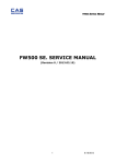
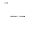
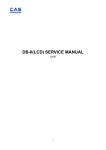
SW-1S/1C/1W Service Manual SW-1S/1C/1W SERVICE MANUAL (Revision 0.1 / 2008.06.17) 1 2/28/2011 SW-1S/1C/1W Service Manual < Table of Contents > 1. Introduction ............................................................................................................................... 3 1.1. Preface .................................................................................................................................... 3 1.2. Precaution ............................................................................................................................. 3 1.3. Specifications ...................................................................................................................... 4 1.4. Key ............................................................................................................................................. 6 1.5. Dimension.............................................................................................................................. 6 1.6. Sealing Method ................................................................................................................... 8 2. Calibration ................................................................................................................................. 10 2.1. General Calibration ........................................................................................................ 10 2.1.1. C4 Setting ........................................................................................................... 11 2.1.1.1. C4-1 Setting................................................................. 11 2.1.1.2. 3. C4-3 Setting................................................................. 11 2.1.2. SPAN Calibration Setting (C-3) .............................................................. 12 2.1.3. Gravity Constant Value Setting (C-9) ................................................ 12 2.1.4. Calibration factor Setting (C-10) .......................................................... 13 2.1.5. Displaying Real A/D Value (C-5) .......................................................... 13 2.1.6. Percent Calibration (C-7) .......................................................................... 14 2.1.7. Battery Calibration (C-8) ........................................................................... 14 The Schematics and Diagram......................................................................................... 15 3.1. System Block Diagram ................................................................................................. 15 3.2. Circuit Diagram ................................................................................................................ 16 3.2.1. Main PCB.............................................................................................................. 16 3.2.2. Power Part (Main PCB) .................................... Error! Bookmark not defined. 4. 3.2.3. Rear Display PCB ............................................................................................ 17 Exploded View ......................................................................................................................... 18 5. Load Cell drawing.................................................................................................................. 20 6. Part Location ............................................................................................................................ 21 6.1. Main PCB (Top) ................................................................................................................ 21 6.2. Main PCB (Bottom) ........................................................................................................ 22 6.3. Rear Display PCB (Top) ............................................................................................... 23 7. Error Messages & Solution............................................................................................... 24 8. Part List ....................................................................................................................................... 25 2 2/28/2011 SW-1S/1C/1W Service Manual 1. Introduction 1.1. Preface Thank you for purchasing of our CAS scale. This scale has been designed with CAS reliability, under rigid quality control and with outstanding performance. WE hope that your departments enjoy with high quality of CAS product. This manual will help you with proper operations and care of the SW-1S/1C/1W series. Please keep it handy for the future references. 1.2. Precaution Make sure that you plug your scale into the proper power outlet. Place the scale on a flat and stable surface. Plug into a power outlet 30 minutes before operations. Keep the scale away from strong EMI noises may cause incorrect weight readings. This scale must be installed in a dry and liquid free environment. Do not subject the scale to sudden temperature changes. Do not subject the platter to sudden shocks. If the scale is not properly level, please adjust the 4 legs at the bottom of the scale (turn legs clockwise or counterclockwise) so as to center the bubble of the leveling gauge inside the indicated circle. 3 2/28/2011 SW-1S/1C/1W Service Manual 1.3. Specifications SW-1S/1C/1W02 SW-1S/1C/1W05 SW-1S/1C/1W10 SW-1S/1C/1W20 SW-1S/1C/1W30 Dual Interval 1 kg / 0.0005 kg 2 kg / 0.001 kg Dual Interval 2.5 kg / 0.001 kg 5 kg / 0.002 kg Dual Interval 4 kg / 0.002 kg 10 kg / 0.005 kg Dual Interval 10 kg / 0.005 kg 20 kg / 0.01 kg Dual Interval 15 kg / 0.005 kg 30 kg/ 0.01kg 1 / 60,000 1 / 60,000 1 / 60,000 1 / 60,000 1/60,000 External 1 / 2,000 1 / 2,500 1 / 2,000 1 / 2,000 1 / 3,000 Max. Tare - 0.9995 kg - 2.449 kg - 3.998 kg - 9.995 kg - 14.995 kg Capacity / e Resolution Internal Display 110 x 35[mm]/43" x 13.8" 5 digit LCD Indicators STABLE, ZERO, TARE, g, kg, lb, oz, Low Battery HI / OK / LO & PCS (SW-1C only) Keys ZERO, TARE, HOLD(Hold Ver.), UNIT(Unit Ver.), MODE(SW1C), POWER Weighing, WaterProof level IP66(SW-1W only) Hold(Hold Ver.), Unit Conversion(Unit Ver.), Counting-Counting SampleRange : 10~100,200,300,400,500 (SW-1C only) Weight Comparison Function : hi, ok, low(SW-1C only) Sleep Mode Function 260(W) x 287(D) x 137(H)[mm] / 102(W) x 113(D) x 54(H)[inch] 278(W) x 317(D) x 141(H)[mm] / 109(W) x 125(D) x 56(H)[inch] (SW-1W : WaterProof Type) 230(W) x 190(D)[mm] / 90.55(W) x 74.80(D)[inch] 247(W) x 195(D)[mm] / 97.24(W) x 76.77(D)[inch] (SW-1W : WaterProof Type) 2.8kg 3.7kg(SW-1W : WaterProof Type) Functions Dimension Platter Size Weight Power 1.5V x 6 units (D size Battery) or 9V Adapter Op.Temperature -10°C ~ +40°C / 14°F ~ 104°F Options 9V Adapter 300mA, Rear Display, Stainless Tray (SW-1S, SW-1C) 4 2/28/2011 SW-1S/1C/1W Service Manual Minimum Voltage About 5.5V Level The Battery Approx. 500hours (Manganese battery)/ 1000hours (Alkaline at 20°C /68°F) Operation time 5 2/28/2011 SW-1S/1C/1W Service Manual 1.4. Key Key ZERO (-O-) Function To set zero point [Set] To do [SET] key in the SETUP mode. TARE To input or cancel the tare (the weight of container). HOLD To make the weight of item stable. This weight is average value. POWER To turn on or off. 1.5. Dimension 1.5.1. SW-1S/1C 6 2/28/2011 SW-1S/1C/1W Manual 1.5.2. SW-1W 7 2/28/2011 Service SW-1S/1C/1W Manual 1.6. Sealing Method 8 2/28/2011 Service SW-1S/1C/1W Manual 9 2/28/2011 Service SW-1S/1C/1W Service Manual 2. Calibration 2.1. General Calibration Pressing and holding calibration switch press [POWER] key to go to calibration mode. User can move to other mode by using [ZERO] key in the calibration mode. User also moves to other sub-modes for each mode by using [TARE] key. Please simply follow below procedure to move to other mode. Calibration Mode: Pressing and holding “Calibration Switch” press [POWER] key. It displays “CAL-0” after “CAL”, and it blinks the version of scale three times. Selecting menu: press [TARE]. ENTER(Setting) : [TARE] key MODE Function CAL 1 Display normalized AD CAL 2 Display Keypad infomationCalibration ‘Zero’ key to select ‘ZERO’ ‘Zero’ key to proceed CAL 3 ‘Midup’ (Refer to table in 2.1.2. C-3) ‘Zero’ key to proceed ‘Full’ Full weight ‘Zero’ key to proceed ‘Middn’ (Refer to table in 2.1.2. C-3), ‘Zero’ key to proceed CAL 4 Option Setting ( Refer to Table 1) CAL 5 Display filtered Raw AD CAL 7 % Calibration CAL 8 Battery calibration CAL 9 Gravity constant Set calibration factor CAL 10 CAL 11 Refer to 2. 1. 4 Set nation(00 : OIML , 01 : NTEP , 02: KOREA) 10 2/28/2011 SW-1S/1C/1W Manual < Modes > 2.1.1. 2.1.1.1. BIT 6~7 C4 Setting C4-1 Setting Initial Zero range BIT5 Last digit enable BIT4 Key zero percent BIT 2~3 BIT0~1 2.1.1.2. Successive tare Zero mark type 3 5% 2 10% 1 3% 0 2% 0 Disable 1 Enable 0 ±3% key zero percent 1 ±2% key zero percent 3 (+), (-) All Direction successive Tare 2 (+) Direction successive Tare 1 (-) Direction successive Tare 0 One Time tare 0 Gross zero indication 1 Net zero indication 2 Both(gross and net) zero indication C4-3 Setting BIT7 Dot Type BIT6 Use Preset tare BIT5 Use Back light BIT4 Use Head message BIT3 Use gram BIT2 Use oz BIT1 Use lb BIT0 Use Kg 0 "." dot 1 "," comma 0 Don't use 1 Use 0 Don't use 1 Use 0 Don't use 1 Use 0 Don't use 1 Use 0 Don't use 1 Use 0 Don't use 1 Use 0 Don't use 1 Use 11 2/28/2011 Service SW-1S/1C/1W Service Manual 2.1.2. SPAN Calibration Setting (C-3) Pressing and holding “Calibration Switch” press [POWER] key. After “CAL” message blinks three times and shows the version of scale, it displays “CAL 1” message. Press [Tare] / [Mode] to display “CAL-3”. Press [Zero] key and then it displays “zero” message. Press [Zero] key and then it displays “midup” message Load middle up weight (Refer to table below) on the platform Press [Zero] key and then it displays “FULL ” message Load full weight on the platform Press [Zero] key and then it displays “middn” message Load middle down weight (Refer to table below) on the platform Press [Zero] key and then it display “CAL 3” message Press [Power] key to save & switch off Table for Cal weights Full Half weight 20 10 10 5 5 2 2.1.3. 2 1 Gravity Constant Value Setting (C-9) Current gravitational Acceleration value is set to 9.7994 m/s2 . Pressing and holding “Calibration Switch” press [POWER] key. After “CAL” message blinks three times and shows the version of scale, it displays “CAL-1” message. Press [ZERO] to display “C-9”. Press [TARE] key, and then “ G-1“ message and “9.7994” will be shown. The first digit,”9” will blink. Input a gravitational acceleration value by using [ZERO] key. Press [TARE] key, and then “G-2“ message blinks.“9.7994” will be shown. The first digit,”9” will blink. Input a gravitational acceleration value by using [ZERO] key. Press [TARE] key to save the gravitational acceleration value, and “C-9 ” message will be shown. 12 2/28/2011 SW-1S/1C/1W Service Manual 2.1.4. Calibration factor Setting (C-10) Pressing and holding “Calibration Switch” press [POWER] key. After “CAL” message blinks three times and shows the version of scale, it displays “CAL-1” message. Press [MODE] or [TARE] to move to display “C-10”. Press [ZERO] key, and then “UNIT “message and “0” will be shown. The first digit,”0” will blink. It means calibration unit is “kg” (0 : kg, 1 : lb) Input a calibration unit by using [MODE] key. Press [ZERO] key and then “CAPA“message blinks. “0015” will be shown. The first digit,”0” will blink. It means a full-capability is “15 (calibration unit, kg or lb)” Input a capability by using [MODE] key to change value [TARE] key to move the right. Press [ZERO] key, and then “MId“message blinks. “0005” will be shown. The first digit,”0” will blink. It means a mid-capability is “05 (calibration unit, kg or lb)” Input a capability by using [MODE] key to change value [TARE] key to move the right. Press [ZERO] key, and then “W-dP “message blinks. “3” will be shown. The first digit,”3” will blink. It means a weight decimal point is “3 (will display 0.000)” Input a weight decimal point by using [MODE] key. Press [ZERO] key, and then “1d “message blinks.“0.005” will be shown. The third digit,”0” will blink. It means a division is “0.005 (calibration unit, kg or lb)” Input a division by using [MODE] key to change value [TARE] key to move the right. Press [ZERO] key, and then “dual “message blinks. “1” will be shown. The third digit,”1” will blink. It means a dual interval is disable. (0 : disable, 1 : enable)” Input a dual interval enable by using [MODE] key. Press [ZERO] key, and then “TARE “message blinks. “0” will be shown. The third digit,”1” will blink. It means a dual interval is disable. (0 : disable, 1 : enable)” Press [ZERO] key to save the calibration factor and “C-10” message will be shown. Turn off scale to save 2.1.5. Displaying Real A/D Value (C-5) Display Raw AD 13 2/28/2011 SW-1S/1C/1W Service Manual 2.1.6. Percent Calibration (C-7) (1) Pressing and holding “Calibration Switch” press [POWER] key. After “CAL” message blinks three times and shows the version of scale, it displays “CAL 1” message. (2) Press [ZERO] to display “CAL-7”. (3) Press [TARE] key and then it displays “per 0 ” message. Select the percent value using the [numeric] key. You can choose 10~90 percent. (Last digit of percent must be 0.) (4) Press [TARE] key and then it displays “zero” message (5) Press [TARE] key and then it displays “pspan ” message (6) Load choice percentage weight of full weight on the platform (7) Press [TARE] key and then it displays “CAL 7” message 2.1.7. Battery Calibration (C-8) (1) Pressing and holding “Calibration Switch” press [POWER] key. After “CAL” message blinks three times and shows the version of scale, it displays “CAL 1” message. (2) Press [ZERO] to display “CAL-8”. (3) Press [TARE] key and then it displays voltage of battery. (4) Change the jumper-pin of main PCB, ‘BAT’ to ‘+5V’. (5) Press [ZERO] key two times and then Press [-] key two times. And then it display ‘500’ (6) Change the jumper-pin of main PCB, ‘+5V’ to ‘BAT’. (7) You can see the calibrated voltage of battery. 14 2/28/2011 SW-1S/1C/1W Service Manual 3. The Schematics and Diagram 3.1. System Block Diagram 15 2/28/2011 SW-1S/1C/1W Service Manual 3.2. Circuit Diagram 3.2.1. Main PCB +5V R11 10 ONE_MODULE1 1 +3.3V ZERO 2 R4 100 S2 ZERO R1 4.7k +3.3V TARE CAL S3 TARE HOLD S4 HOLD 0 0 2 R3 100 C2 C3 C1 1nF 1nF 1nF +3.3V Rx 6 Tx 7 CAL PART JP1 8 9 BUZZER1 J2 1 KTA1298 Q1 BUZZER 0 0 R6 100 10 +3.3V 1 2 3 4 11 Tx Rx 12 0 0 RS232 CONNECTOR PART KEY & BUZZER PART PROGRAM PART HOLD 13 POWER_CHK 14 TARE 15 ZERO 16 POWER_CON 17 BUZZER 18 A_Vcc AIN+ A_GND AIN- Bat_chk 5 10K PSEN 3 4 1 2 R2 R5 100 0 J1 BAT_CHK A_GND P1.6 P1.0 P1,7 P0.0 Rx P0.1 Tx P0.2 P3.2 P0.3 P3.3 P0.4 P3.4 P0.5 P3.5 P0.6 P3.6 P0.7 P3.7 PSEN P2.0 I2C_SDA P2.1 I2C_CLK P2.2 D_Vcc P2.3 D_GND P1.1 RTC_Power 36 SIG_IN+ 35 SIG_IN- 34 33 CAL 32 LCD_CS 31 LCD_WR 30 LCD_DATA 0 29 28 27 26 25 24 PSEN 23 22 +3.3V 21 20 19 0 K C A L B J7 COM0 COM1 COM2 COM3 SEG0 SEG1 SEG2 SEG3 SEG4 SEG5 SEG6 U2 LCD1 SEG7 SEG6 SEG5 SEG4 SEG3 SEG2 SEG1 SEG0 CS RD WR DATA VSS OSCO OSCI VLCD VDD IRQ BZ BZ COM0 COM1 COM2 COM3 SEG7 SEG6 SEG5 SEG4 SEG3 SEG2 SEG1 SEG0 1 2 3 4 5 6 7 8 9 10 11 12 13 14 15 16 17 18 19 20 21 22 23 24 C0 C1 C2 C3 S2/S3/S4/HI STABLE/L/O/K 1F/1G/1E/1D 1A/1B/1C/ / /1P/1Z 2F/2G/2E/2D 2A/2B/2C/ / /2P/2Z 3F/3G/3E/3D 3A/3B/3C/ / /3P/3Z 4F/4G/4E/4D 4A/4B/4C/ / /4P/4Z 5F/5G/5E/5D 5A/5B/5C/ OZ/LB/ K/ G PCS LCD_CS LCD_WR LCD_DATA +5V R7 2.2K C7 0.1uF COM0 COM1 COM2 COM3 0 HT1621B-48 SSOP 1 2 3 4 COM0 COM1 COM2 COM3 5 SEG0 6 SEG1 7 SEG2 8 SEG3 9 SEG4 10 SEG5 11 SEG6 12 SEG7 13 SEG8 14 SEG9 15 SEG10 16 SEG11 17 SEG12 18 SEG13 19 SEG14 20 SEG15 21 SEG16 22 SEG17 MODULE CONNECTOR PART 1 2 3 4 5 6 7 8 9 10 11 SEG7 SEG8 SEG9 SEG10 SEG11 SEG12 SEG13 SEG14 SEG15 SEG16 SEG17 1 2 3 4 5 6 7 8 9 10 11 U1 +5V XC6204C502MR 5 VIN VOUT + C5 C6 0.1uF 100u/16v VSS SEG8 SEG9 SEG10 SEG11 SEG12 SEG13 SEG14 SEG15 SEG16 SEG17 SEG18 SEG19 SEG20 SEG21 SEG22 SEG23 SEG24 SEG25 SEG26 SEG27 SEG28 SEG29 SEG30 SEG31 D E R 48 47 46 45 44 43 42 41 40 39 38 37 36 35 34 33 32 31 30 29 28 27 26 25 2 SEG8 SEG9 SEG10 SEG11 SEG12 SEG13 SEG14 SEG15 SEG16 SEG17 OneModule CE 1 3 C4 0.1uF SW-II LCD J8 L1 0 1 0 2 B+ L 102S 1 2 + C11 330u/25vL2 1 LCD PART U3 +3.3V J3 2 ADAPTOR JACK J4 L 102S XC6204C332MR 1 1 5 2 L3 VOUT + C8 EX- 2 1 2 SIG+ 3 1 L4 2 0 1 SIG- 4 1 L5 2 1 FG 5 C9 0.1uF 100u/16v L6 VIN 2 SIG_IN+ L8 2 SIG_IN- VSS EX+ +5V CE 1 +5V C12 0.01uF / 3kv 0 0 +3.3V J6 JP2 BAT, +5V change R8 10k 3 : RED 2 : GREEN 1 : BLUE BAT 1 2 L7 BR9 100k D1 POWER_CHK 3 2 1 1 2 3 C10 0.1uF 3 2 J5 2 1 3 KDS184 TP2 TP1 REGULATOR PART BAT_CHK S1 ON/OFF 0 LOADCELL PART POWER_CON 0 R10 1k Title 0 Size A3 Date: 16 SW1S1C (MODULE VER.) Document Number Rev A 6100-PSW-0000 Tuesday , June 17, 2008 2/28/2011 Sheet 1 of 1 SW-1S/1C/1W Service Manual 3.2.2. Rear Display PCB K C A L B J1 LCD1 C0 C1 C2 C3 SW-II LCD COM0 COM1 COM2 COM3 5 SEG0 6 SEG1 7 SEG2 8 SEG3 9 SEG4 10 SEG5 11 SEG6 12 SEG7 13 SEG8 14 SEG9 15 SEG10 16 SEG11 17 SEG12 18 SEG13 19 SEG14 20 SEG15 21 SEG16 22 SEG17 COM0 COM1 COM2 COM3 SEG0 SEG1 SEG2 SEG3 SEG4 SEG5 SEG6 1 2 3 4 5 6 7 8 9 10 11 D E R S2/S3/S4/HI STABLE/L/O/K 1F/1G/1E/1D 1A/1B/1C/ / /1P/1Z 2F/2G/2E/2D 2A/2B/2C/ / /2P/2Z 3F/3G/3E/3D 3A/3B/3C/ / /3P/3Z 4F/4G/4E/4D 4A/4B/4C/ / /4P/4Z 5F/5G/5E/5D 5A/5B/5C/ OZ/LB/ K/ G PCS 1 2 3 4 SEG7 SEG8 SEG9 SEG10 SEG11 SEG12 SEG13 SEG14 SEG15 SEG16 SEG17 1 2 3 4 5 6 7 8 9 10 11 J2 Title SW-1S/1C/1W REAR DISPLAY PCB Size A Date: 17 Document Number 6110-PSW-0000-0 Tuesday , June 17, 2008 Rev 0 Sheet 1 of 2/28/2011 1 SW-1S/1C/1W Service Manual 4. Exploded View 4.1. SW-1S/1C 18 2/28/2011 SW-1S/1C/1W Service Manual 4.2. SW-1W 19 2/28/2011 SW-1S/1C/1W Service Manual 15 5. Load Cell drawing 25 112 112 SW (spring elem ent) 2090501 20 2/28/2011 00 SW-1S/1C/1W Service Manual 6. Part Location 6.1. Main PCB (Top) 21 2/28/2011 SW-1S/1C/1W Service Manual 6.2. Main PCB (Bottom) 22 2/28/2011 SW-1S/1C/1W Service Manual 6.3. Rear Display PCB (Top) 23 2/28/2011 SW-1S/1C/1W Manual 7. Error Messages & Solution Error Message Description on Display Solution Remove unstable facts. "Err 0" The "Err 0" occurs when scale is not stable. "Err 1" The "Err 1" occurs when a current zero point has Please call your CAS dealer. shifted from the last span calibration. "Err 2" The "Err 2" is not a real error. Only it prompts Please call your CAS return CAL switch to the normal position. dealer. "Err 3" The "Err 3" is an overload error. "Err 9" The "Err 9" is no weight error. When scale is in counting mode, you must load the weight. Please load the weight If you have no weight on your scale, you can see on your tray. this error message. “Err 11” The "Err 11" means a writing error of the internal If it still has "Err 11", nonvolatile memory. To recognize this error, be replace the digital sure to check the voltage on the circuit and do module. calibration procedures. “Err 12” Enter each condition The "Err 12" warns that the scale has lost the codes again. parameters for weighing regulations or has lost Please try a span the factors for a digital span calculation. calibration again if still not fixed. “Err 14” The "Err 14" means calibration range is not Please call your CAS correct. dealer. 24 Please remove the weight. 2/28/2011 Service SW-1S/1C/1W Service Manual 8. Part List 8.1.1 SW-1S/1C/1W (Electronic part) 1.1 MAIN PCB ASS'Y [140SW5EMAPUN0101] No Part Name Specification MAIN PCB ASS'Y Part Number Q'ty 140SW5EMAPUN0101 1 Remark MAIN PCB ASS'Y 1 PCB-MAIN 6100-PSW-0000-A(SW-1S) 6100PSW0000A 1 MAIN PCB 2 ONE MODULE ONE MODULE 6PA0A0000000 1 U4(ONE MODULE NO OPTION) 3 IC(REGULATOR) XC6204C502MR(5.0V) 6220IS0C5020 1 U1 4 IC(REGULATOR) XC6204C332MR(3.3V) 6220IS0C3320 1 U3 5 IC(LCD DRIVER) HOLTEX HT1621B 6224I0016210 1 U2 6 TRANSISTOR CHIP KTA1504 SY 6281I0015040 1 Q1 25 2/28/2011 SW-1S/1C/1W Service Manual 7 DIODE-CHIP KDS184 6294ICP01840 8 RESISTOR-CHIP 1/10W WR06X0000JT(0Ω) 6527ID00000A 9 RESISTOR-CHIP 1/10W RR1220P-100D(10Ω) 6527ID001000 1 R11 10 RESISTOR-CHIP 1/10W RR1220P-222D(2.2K) 6527ID300220 1 R7 11 RESISTOR-CHIP 1/10W RR1220P-104D(100K) 6527ID310000 4 R1,2,8,9 12 RESISTOR-CHIP 1/10W RR1220P-102D(1K) 6527ID300100 1 R10 13 RESISTOR-CHIP 1/10W RR1220P-101D(100) 6527ID010000 5 R3,4,5,6 14 INDUCTANCE HB-1M2012-102JT(TP2,LP2,DBB) 6670T0001020 8 L1,2,3,4,5,6,7,8 15 CONDENSER-CERAMIC 0.01uF/3KV 6710CAP0103B 1 C12 16 CONDENSER-ELECTRIC 330uF/25V 6704C2503300 1 C11 17 CONDENSER-ELECTRIC 100uF/16V 6704C1601000 2 C5,8 18 CONDENSER-CHIP CL21F 102KBNC 6712CHP01020 3 C1,2,3 26 1 D1 17 CON1~17 2/28/2011 SW-1S/1C/1W Service Manual 19 CONDENSER-CHIP CL21F 104KBNC 6712CHP01040 5 C4,6,7,9,10 20 CONNECTOR(WAFER) LAL0640-02 (LAW250-02) 7809CAL00020 3 J1,3,6 21 CONNECTOR(WAFER) LAL0640-03 (LAW250-03) 7809CAL00030 1 J4 22 CONNECTOR(WAFER) LAL0640-11 (LAW250-11) 7809CAL00110 2 LCD_CON 23 PIEZO BUZZER APR,ADR(CHINA) 7002Z0000000 1 BUZZER 24 TACT S/W KPT-1105B(DJTA-1102C) 7600STA1105B 4 ZERO,TARE,HOLD,ON/OFF KEY 25 JUMPER 10PIN 7821CJM00100 1 JP1(2PIN),JP2(3PIN),J2(4PIN) 26 BRACKET-LCD DTE 101754AJP 1(SW) 2000A0000660 1 LCD1 27 LCD 114.8*44.8*BLACK(SW-1) 7212D0040920 1 28 GROUND WIRE 100mm(DB-Ⅱ) 7860GND01000 1 FG 1.2 REAR DISPLAY PCB ASS'Y [140SW1MDIPUN0104] 27 2/28/2011 SW-1S/1C/1W Service Manual No Part Name Specification Part Number Q'ty Remark REAR DISPLAY PCB ASS'Y SW-1S 140SW1MDIPUN0104 1 REAR DISPLAY PCB ASS'Y 1 BRACKET-LCD DTE 101754AJP 1(SW) 2000A0000660 1 2 PCB-DISPLAY 6110-PSW-1130-0(SW) 6110PSW11300 1 3 LCD DTE 101754AJP 1(SW) 7212D0040920 1 LCD 4 FLAT CABLE CONNECTOR (10+11)P*350mm(CORE,SW 양면) 7850W0021350 1 1.3 CAL PCB ASS'Y [140SW6ECAPUN0101] No Part Name CAL PCB ASS'Y Specification SW-WR Part Number Q'ty 140SW6ECAPUN0101 28 2/28/2011 Remark 1 CAL PCB ASS'Y SW-1S/1C/1W Service Manual 1 PCB-CAL 6151-PSW-0000-0(SW1-S/1C) 6151PSW00000 1 2 TACT S/W 11902(DJTA-1102) 7600STA19020 1 3 CONNECTOR WIRE 2P*140m/m(SW) 7840W000214B 1 8.1.2 SW-1S/1C (Mechanical part) 1.1 BODY ASS'Y [140SW4SBODUN0103] SW-1S 반제품 140SW4SBODUN0103 BODY ASS'Y SW-1S BODY ASS'Y 자재 1590A000006A BATTERY SPRING B ø0.9*ø16*50*19-SUS(SW-1) 1 BODY ASS'Y 자재 1590A000007B BATTERY SPRING C ø0.9*ø16*37*8 1 BODY ASS'Y 자재 1590A000014A BATTERY SPRING A ø0.9*ø16*50*19(SW-1) 1 BODY ASS'Y 자재 1590A0000240 BATTERY SPRING D ø0.9*ø16*37*26-SWP(SW-1) 1 BODY ASS'Y 자재 7840W000219B CONNECTOR WIRE 2P*190mm SW-WP (+)BATTERY WIRE 1 BODY ASS'Y 자재 7840W0002230 CONNECTOR WIRE 2P*230mm SW-WP (-)BATTERY WIRE 1 29 2/28/2011 Q'ty SW-1S/1C/1W Service Manual BODY ASS'Y 자재 7840W0003230 CONNECTOR WIRE 3P*230mm-303(EP,SW) C/T BOX ASS'Y SW-1S 1 1.2 C/T BOX ASS'Y [140SW4MCTBUN0103] SW-1S 반제품 C/T BOX ASS'Y 자재 7510P0911220 ADAPTOR 110/220V9V/300mA(EP,PW) 1 C/T BOX ASS'Y 자재 7520P0001500 BATTERY-MN R20-1.5V-D(TP,SW) 6 C/T BOX ASS'Y 자재 9002SW300330 MANUAL SW-1S1C1W(영문) 1 C/T BOX ASS'Y 자재 9100SW00133B C/T BOX SW-1(360*297*215, 영문) 1 C/T BOX ASS'Y 자재 9100SW004300 C/T BOX 615*375*435(SW-1/4) 0.25 C/T BOX ASS'Y 자재 9203AS000070 STYROFOAM BOX 352.5*191*146(SW-1) 1 C/T BOX ASS'Y 자재 9203AS000080 STYROFOAM BOX 352.5*191*146(SW-1) 1 C/T BOX ASS'Y 자재 9300A0000020 POLY BAG 90*150*0.05T(FUSE) 1 140SW4MCTBUN0103 30 2/28/2011 SW-1S/1C/1W Service Manual C/T BOX ASS'Y 자재 9301A0000030 POLY BAG 170*250*0.05T(MANUAL) 1 C/T BOX ASS'Y 자재 9302A000005B POLY BAG 270*350*0.04T(MW,PW)(SET)HD 1 C/T BOX ASS'Y 자재 9305A000001B POLY BAG 500*650*0.04T(S2000)(SET,HD) 1 C/T BOX ASS'Y 자재 9400A0000460 SILICAGEL 10g 2 C/T BOX ASS'Y 자재 9900A0000010 봉인납 수출용 1 C/T BOX ASS'Y 자재 9900A0000020 SEALING WIRE 300M/ROLL 0.001 1.3 BODY ASS'Y [140SW4MBODUN0103] SW-1S 반제품 BODY ASS'Y SW-1S 140SW4MBODUN0103 BODY ASS'Y 자재 1000A0000790 SEALING PLATE 29*69.8*1T(SW-Ⅰ) 1 BODY ASS'Y 자재 1260A0000090 BOLT-SEALING M4*40(NI)SW-1 1 BODY ASS'Y 자재 1502A0004060 SCREW-MACHINE(PH) M4*6 1 31 2/28/2011 SW-1S/1C/1W Service Manual BODY ASS'Y 자재 1510A0003060 SCREW-TAPPING(PH)-1 M3*6 3 BODY ASS'Y 자재 1510A0003080 SCREW-TAPPING(PH)-1 M3*8 4 BODY ASS'Y 자재 1510A0004120 SCREW-TAPPING(PH)-1 M4*12 4 BODY ASS'Y 자재 1510A0004200 SCREW-TAPPING(PH)-1 M4*20 4 BODY ASS'Y 자재 2040-103-0013-0 BATTERY COVER SW Violet (비난연) 1 BODY ASS'Y 자재 2040-103-0012-0 BODY SW Violet (비난연) 1 BODY ASS'Y 자재 2008A000001B FOOT PVCø40*42(SW-1) 4 BODY ASS'Y 자재 2022A0000041 WATER LEVEL GAGE ø14.9*8(S-2000)상보 1 BODY ASS'Y 자재 7642S0000600 METAL CLAMP 6N 5 1.4 L/C BRACKET ASS'Y [140SW4MLCBUN0103] SW-1S 반제품 140SW4MLCBUN0103 32 BRACKET ASS'Y SW-1S 2/28/2011 SW-1S/1C/1W Service Manual L/C BRACKET ASS'Y 자재 1030A000039A BRACKET-L/C LOWER SPC 120*100*4T(SW-1) 1 L/C BRACKET ASS'Y 자재 1030A000040B BRACKET L/C-TOP SPC160*110*3.2T(SW-5,10K) 1 L/C BRACKET ASS'Y 자재 1130A0000020 BOLT-LIMIT M5*33.8(Zn 황)(SW-10,20,30) 2 L/C BRACKET ASS'Y 자재 1130A0000030 BOLT-LIMIT M5*34.9(Zn 백)(SW-2,5,10) 2 L/C BRACKET ASS'Y 자재 1510A0004120 SCREW-TAPPING(PH)-1 M4*12 4 L/C BRACKET ASS'Y 자재 1530MSU05150 BOLT-WRENCH M5*15-SUS 4 L/C BRACKET ASS'Y 자재 1532A0004120 BOLT-WRENCH(ST) M4*12(SP 30K,60lb 2EA) 1 L/C BRACKET ASS'Y 자재 1540A0005000 NUT(HEX) M5*0.8 4 L/C BRACKET ASS'Y 자재 1540MSU04000 NUT(HEX) M4*07-SUS 1 L/C BRACKET ASS'Y 자재 1552MSU05000 WASHER(OTO) ø5-SUS 4 L/C BRACKET ASS'Y 자재 2600A000051A TRAY RUBBER B NBRø17.4*21(SW2,5,10K)BLACK 4 33 2/28/2011 SW-1S/1C/1W Service Manual 1.5 UPPER CASE ASS'Y [140SW4MUPCUN0103] SW-1S 반제품 UPPER CASE ASS'Y SW-1S 140SW4MUPCUN0103 UPPER CASE ASS'Y 자재 1510A0004200 SCREW-TAPPING(PH)-1 M4*20 4 UPPER CASE ASS'Y 자재 1563A0003080 RIVET @3.2*8 2 UPPER CASE ASS'Y 자재 1810SW000332 SPEC PLATE SW-1(영공)(SW,SW-II 공용) 1 UPPER CASE ASS'Y 자재 2040-103-0014-0 UPPER CASE SW Violet (비난연) 1 UPPER CASE ASS'Y 자재 2040-103-0015-0 TRAY SW Violet (비난연) 1 UPPER CASE ASS'Y 자재 2000A0000750 DISPLAY COVER ABS750 124.7*53.7*3.5(SW)(R) 1 UPPER CASE ASS'Y 자재 2010A0000080 WATER LEVEL GAGE COVER ø24.8*0.5T(LP-1,Ⅱ,SW) 1 UPPER CASE ASS'Y 자재 2050SWA10222 DISPLAY COVER SW-1(10kg)유럽공용 심볼 1 UPPER CASE ASS'Y 자재 2200SW000220 KEY BOARD PAD SW-1(S)(HOLD)유럽공용심볼 1 UPPER CASE ASS'Y 자재 2632A0000160 DISPLAY COVER TAPE 124*53(SW-1) 1 34 2/28/2011 SW-1S/1C/1W Service Manual 1.6 SW-5L [LLBSW0153G000000] SW 자재 9800A0000040 LOCKING PAINT 접착제(200G)(녹색) 0.002 SW 자재 8ZSW0KK00500 LOAD CELL SW-5L(CHINA) SW 자재 9800A000001A 순간본드 ALTECO-EE(20g) 0.002 SW 자재 9800A0000030 BOND #575 180ml 0.002 1 8.1.3 SW-1W (Mechanical part) 1.1 BODY ASS'Y SW-1W 반제품 BODY ASS'Y SW-1W Q'ty BODY ASS'Y 1000A0002270 CONNECTOR RUBBER PLATE SW-1W(39.6*29.6*1.2t) 1 BODY ASS'Y 1005A0001150 SEALING WASHER ø5*10 (SW-WATERPROOF) 8 BODY ASS'Y 1030A0002030 SEALING PLATE 35.2*26*1t DB-II 1 35 2/28/2011 SW-1S/1C/1W Service Manual BODY ASS'Y 1265A0000010 BOLT-SEALING M3*9(황동,HEAD 3mm 포함) 2 BODY ASS'Y 1502MSU05120 SCREW-MACHINE(PH) M5*0.8*12-SUS 8 BODY ASS'Y 1510A0003060 SCREW-TAPPING(PH)-1 M3*6 2 BODY ASS'Y 1510A0003080 SCREW-TAPPING(PH)-1 M3*8 8 BODY ASS'Y 1510A0004060 SCREW-TAPPING(PH)-1 M4*6 1 BODY ASS'Y 1510MSU04120 SCREW-TAPPING(PH)-1 M4*12-SUS 6 BODY ASS'Y 1561MSU05000 E-RING ø5*ø11*0.6-SUS 1 BODY ASS'Y 2040-103-0016-0 BODY SW-1W Violet (비난연) 1 BODY ASS'Y 2040-103-0017-0 BATTERY COVER SW-1W Violet (비난연) 1 BODY ASS'Y 2040-103-0020-0 BATTERY COVER BOLT SW-1W Violet (비난연) 1 BODY ASS'Y 2040-103-0021-0 BATTERY COVER GUIDE SW-1W Violet (비난연) 1 BODY ASS'Y 2008A000001B FOOT PVCø40*42(SW-1) 4 36 2/28/2011 SW-1S/1C/1W Service Manual BODY ASS'Y 2022A0000041 WATER LEVEL GAGE ø14.9*8(S-2000)상보 1 BODY ASS'Y 2600A000084A BATTERY COVER GASKET SW-WATERPROOF (150.2*187.8*4) 1 BODY ASS'Y 2600A0000850 CONNECTOR RUBBER SW-WATERPROOF (39.5*45.5*15) 1 BODY ASS'Y 2630A0000030 O-RING P5(HBB) 8 C/T BOX ASS'Y SW-1W 1.2 C/T BOX ASS'Y SW-1W 반제품 C/T BOX ASS'Y 자재 7510P0911220 ADAPTOR 110/220V9V/300mA(EP,PW) 1 C/T BOX ASS'Y 자재 7520P0001500 BATTERY-MN R20-1.5V-D(TP,SW) 6 C/T BOX ASS'Y 9100SW00133B C/T BOX SW-1(360*297*215, 영문) 1 C/T BOX ASS'Y 9100SW004300 C/T BOX 615*375*435(SW-1/4) C/T BOX ASS'Y 9203AS000200 STYROFOAM BOX SW-WATERPROOF(R) 352.5*146*191 37 2/28/2011 0.25 1 SW-1S/1C/1W Service Manual C/T BOX ASS'Y 9203AS000210 STYROFOAM BOX SW-WATERPROOF(L) 352.5*146*191 1 C/T BOX ASS'Y 9300A0000020 POLY BAG 90*150*0.05T(FUSE) 1 C/T BOX ASS'Y 9301A0000030 POLY BAG 170*250*0.05T(MANUAL) 1 C/T BOX ASS'Y 9302A000005B POLY BAG 270*350*0.04T(MW,PW)(SET)HD 1 C/T BOX ASS'Y 9305A000001B POLY BAG 500*650*0.04T(S2000)(SET,HD) 1 C/T BOX ASS'Y 9400A0000460 SILICAGEL 10g 2 C/T BOX ASS'Y 9900A0000010 봉인납 수출용 1 C/T BOX ASS'Y 9900A0000020 SEALING WIRE 300M/ROLL 0.1 1.3 BODY ASS'Y SW-1W BODY ASS'Y 반제품 BODY ASS'Y 1590A000006A BATTERY SPRING B 38 SW-1W ø0.9*ø16*50*19-SUS(SW-1) 2/28/2011 1 SW-1S/1C/1W Service Manual BODY ASS'Y 1590A000007B BATTERY SPRING C ø0.9*ø16*37*8 1 BODY ASS'Y 1590A000014A BATTERY SPRING A ø0.9*ø16*50*19(SW-1) 1 BODY ASS'Y 1590A0000240 BATTERY SPRING D ø0.9*ø16*37*26-SWP(SW-1) 1 BODY ASS'Y 7840W000219B CONNECTOR WIRE 2P*190mm SW-WP (+)BATTERY WIRE 1 BODY ASS'Y 7840W0002230 CONNECTOR WIRE 2P*230mm SW-WP (-)BATTERY WIRE 1 BODY ASS'Y 7840W0003230 CONNECTOR WIRE 3P*230mm-303(EP,SW) 1 1.4 L/C BRACKET ASS'Y SW-1W 반제품 BRACKET ASS'Y SW-1W L/C BRACKET ASS'Y 1005A0001150 SEALING WASHER ø5*10 (SW-WATERPROOF) 2 L/C BRACKET ASS'Y 1030A000039A BRACKET-L/C LOWER SPC 120*100*4T(SW-1) 1 L/C BRACKET ASS'Y 1100A0000740 BRACKET-L/C TOP SW-WATERPROOF(103.9*73.9*14.5) 1 39 2/28/2011 SW-1S/1C/1W Service Manual L/C BRACKET ASS'Y 1130A0000030 BOLT-LIMIT M5*34.9(Zn 백)(SW-2,5,10) 4 L/C BRACKET ASS'Y 1510MSU04120 SCREW-TAPPING(PH)-1 M4*12-SUS 4 L/C BRACKET ASS'Y 1530MSU05100 BOLT-WRENCH M5*1.0*10-SUS 2 L/C BRACKET ASS'Y 1530MSU05150 BOLT-WRENCH M5*15-SUS 4 L/C BRACKET ASS'Y 1532A0004120 BOLT-WRENCH(ST) M4*12(SP 30K,60lb 2EA) 1 L/C BRACKET ASS'Y 1540A0005000 NUT(HEX) M5*0.8 4 L/C BRACKET ASS'Y 1540MSU04000 NUT(HEX) M4*07-SUS 1 L/C BRACKET ASS'Y 1552MSU05000 WASHER(OTO) ø5-SUS 4 L/C BRACKET ASS'Y 2040-103-0022-0 PLATFORM SW-1W Violet (비난연) 1 L/C BRACKET ASS'Y 2630A0000030 O-RING P5(HBB) 2 1.5 UPPER CASE ASS'Y 40 2/28/2011 SW-1S/1C/1W Service Manual SW-1W 반제품 UPPER CASE ASS'Y SW-1W UPPER CASE ASS'Y 1000A0002280 BELLOWS PLATE SW-1W(ø129.3*1.6t) 1 UPPER CASE ASS'Y 1000A0002290 TRAY SW-1W(253.4*202*17.8)(SUS) 1 UPPER CASE ASS'Y 1502MSU03080 SCREW-MACHINE(PH) M3*8-SUS 4 UPPER CASE ASS'Y 1510MSU04120 SCREW-TAPPING(PH)-1 M4*12-SUS 6 UPPER CASE ASS'Y 1563A0003080 RIVET @3.2*8 2 UPPER CASE ASS'Y 1575A0012100 SCREW IN VENT M12*10(EPTFE)(WATERPROOF) 1 UPPER CASE ASS'Y 2040-103-0018-0 UPPER CASE SW-1W Violet (비난연) 1 UPPER CASE ASS'Y 2040-103-0019-0 TRAY SW-1W Violet (비난연) 1 UPPER CASE ASS'Y 2015A0000300 DISPLAY FILTER SW-WATERPROOF (124.4*55.6*1t) 1 UPPER CASE ASS'Y 2021SW800331 SHEET SW-1W(TRAY SHEET),ENGLISH 1 UPPER CASE ASS'Y 2600A0000860 UPPER CASE GASKET SW-WATERPROOF (264.5*307.9*7) 1 41 2/28/2011 SW-1S/1C/1W Service Manual UPPER CASE ASS'Y 2620A0000310 BELLOWS SW-WATERPROOF (ø129.3*17) 1 1.6 UPPER CASE ASS'Y SW-1W 반제품 IMAGE ASS'Y SW-1W IMAGE ASS'Y 1810SW000332 SPEC PLATE SW-1(영공)(SW,SW-II 공용) 1 IMAGE ASS'Y 2050W5B20330 DISPLAY COVER SW-1W(20kg)(ENGLISH)(1/10000) 1 IMAGE ASS'Y 2200W5A20330 KEY BOARD PAD SW-1W(20kg)(ENGLISH)(1/10000) 1 IMAGE ASS'Y 9002SW300330 MANUAL SW-1S1C1W(영문) 1 0.002 1.7 SW-5L [LLBSW0153G000000] SW 자재 9800A0000040 LOCKING PAINT 접착제(200G)(녹색) SW 자재 8ZSW0KK00500 LOAD CELL SW-5L(CHINA) 42 2/28/2011 1 SW-1S/1C/1W Service Manual SW 자재 9800A000001A 순간본드 ALTECO-EE(20g) 0.002 SW 자재 9800A0000030 BOND #575 180ml 0.002 43 2/28/2011