1
'HOO/DWLWXGH&63RUWDEOH&RPSXWHUV
6(59,&(0$18$/
ZZZGHOOFRP
'HOO/DWLWXGH&63RUWDEOH&RPSXWHUV
6(59,&(0$18$/
ZZZGHOOFRP
____________________
Information in this document is subject to change without notice.
© 1999 Dell Computer Corporation. All rights reserved.
Reproduction in any manner whatsoever without the written permission of Dell Computer Corporation is strictly forbidden.
Trademarks used in this text: Dell, the DELL logo, and Latitude are trademarks of Dell Computer Corporation.
Other trademarks and trade names may be used in this document to refer to either the entities claiming the marks and names or their products.
Dell Computer Corporation disclaims any proprietary interest in trademarks and trade names other than its own.
November 1999
P/N 0708R Rev. A01
&RQWHQWV
Recommended Tools. . . . . . . . . . . . . . . . . . . . . . . . . . . . . . . . . . . . . . . . . . . .2
Preparing to Work Inside Your Computer . . . . . . . . . . . . . . . . . . . . . . . . . . . .2
Screw Identification and Tightening . . . . . . . . . . . . . . . . . . . . . . . . . . . . . . . .3
ZIF Connectors . . . . . . . . . . . . . . . . . . . . . . . . . . . . . . . . . . . . . . . . . . . . . . . .5
Removing Field-Replaceable Parts and Assemblies . . . . . . . . . . . . . . . . . . . .6
Hard-Disk Drive Assembly. . . . . . . . . . . . . . . . . . . . . . . . . . . . . . . . . . . . .7
Memory Module Cover . . . . . . . . . . . . . . . . . . . . . . . . . . . . . . . . . . . . . . .7
Bottom Memory Module. . . . . . . . . . . . . . . . . . . . . . . . . . . . . . . . . . . . . .8
Top Memory Module. . . . . . . . . . . . . . . . . . . . . . . . . . . . . . . . . . . . . . . . .9
Display Assembly . . . . . . . . . . . . . . . . . . . . . . . . . . . . . . . . . . . . . . . . . .11
Display-Assembly Bezel. . . . . . . . . . . . . . . . . . . . . . . . . . . . . . . . . . . . . .13
Display-Assembly Latch. . . . . . . . . . . . . . . . . . . . . . . . . . . . . . . . . . . . . .15
LCD Panel . . . . . . . . . . . . . . . . . . . . . . . . . . . . . . . . . . . . . . . . . . . . . . .15
Replacing a Sharp LCD panel with a Sharp LCD panel or Replacing a
Samsung LCD panel with a Samsung LCD panel . . . . . . . . . . . . . . . . . .15
Replacing a Sharp LCD Panel with a Samsung LCD Panel or Replacing a
Samsung LCD Panel with a Sharp LCD Panel. . . . . . . . . . . . . . . . . . . . .16
Removing the Packing Bezel on a New Sharp LCD Panel. . . . . . . . .17
Packing a Defective Sharp LCD Panel for Return Shipping. . . . . . . .17
Keyboard Assembly. . . . . . . . . . . . . . . . . . . . . . . . . . . . . . . . . . . . . . . . .18
Palmrest Assembly . . . . . . . . . . . . . . . . . . . . . . . . . . . . . . . . . . . . . . . . .19
Bottom Assembly . . . . . . . . . . . . . . . . . . . . . . . . . . . . . . . . . . . . . . . . . .22
Reserve Battery . . . . . . . . . . . . . . . . . . . . . . . . . . . . . . . . . . . . . . . .22
Main Battery . . . . . . . . . . . . . . . . . . . . . . . . . . . . . . . . . . . . . . . . . . .23
Main Battery Release Latch. . . . . . . . . . . . . . . . . . . . . . . . . . . . . . . .23
Thermal Cooling Solution. . . . . . . . . . . . . . . . . . . . . . . . . . . . . . . . . .24
System Board Assembly . . . . . . . . . . . . . . . . . . . . . . . . . . . . . . . . . .26
Touch Pad . . . . . . . . . . . . . . . . . . . . . . . . . . . . . . . . . . . . . . . . . . . .29
Fan Assembly . . . . . . . . . . . . . . . . . . . . . . . . . . . . . . . . . . . . . . . . . .29
,QGH[
)LJXUHV
Figure 1. Computer Orientation. . . . . . . . . . . . . . . . . . . . . . . . . . . . . . . . .1
Figure 2. Main Battery Assembly Removal. . . . . . . . . . . . . . . . . . . . . . . .3
i
Figure 3. Screw Identification . . . . . . . . . . . . . . . . . . . . . . . . . . . . . . . . . .3
Figure 4. Disconnecting an Interface Cable. . . . . . . . . . . . . . . . . . . . . . . .5
Figure 5. Exploded ViewComputer . . . . . . . . . . . . . . . . . . . . . . . . . . . .6
Figure 6. Hard-Disk Drive Assembly Removal. . . . . . . . . . . . . . . . . . . . . .7
Figure 7. Bottom Memory Module Removal. . . . . . . . . . . . . . . . . . . . . . .8
Figure 8. Top Memory Module Removal . . . . . . . . . . . . . . . . . . . . . . . . .9
Figure 9. Status Indicator Panel Removal . . . . . . . . . . . . . . . . . . . . . . . .10
Figure 10. Display Assembly Removal . . . . . . . . . . . . . . . . . . . . . . . . . .11
Figure 11. Sharp Display-Assembly Bezel Removal . . . . . . . . . . . . . . . .13
Figure 12. Samsung Display-Assembly Bezel Removal. . . . . . . . . . . . . .14
Figure 13. Removing the Keyboard-Assembly Screws. . . . . . . . . . . . . .18
Figure 14. Removing the Palmrest-Assembly Screws . . . . . . . . . . . . . .19
Figure 15. Palmrest Assembly Removal . . . . . . . . . . . . . . . . . . . . . . . . .21
Figure 16. Bottom Assembly. . . . . . . . . . . . . . . . . . . . . . . . . . . . . . . . . .22
Figure 17. Main Battery Release Latch . . . . . . . . . . . . . . . . . . . . . . . . . .23
Figure 18. Thermal Cooling Solution Removal. . . . . . . . . . . . . . . . . . . . .24
Figure 19. System Board Assembly Removal. . . . . . . . . . . . . . . . . . . . .26
Figure 20. Microprocessor Removal . . . . . . . . . . . . . . . . . . . . . . . . . . . .29
7DEOHV
ii
Table 1. Screw Placement Mat with Component Screw Counts and Sizes. . 4
iii
5HDG7KLV)LUVW
A prerequisite for using this manual to service Dell computer systems is a basic
knowledge of PCs and prior training in PC troubleshooting techniques. In addition
to information provided in this manual, Dell provides theUsers Guide for troubleshooting procedures and instructions on using the Dell Diagnostics to test
the computer system.
1RWHV1RWLFHVDQG&DXWLRQV
Throughout this guide, blocks of text may be accompanied by an icon and printed
in bold type or in italic type. These blocks are notes, notices, and cautions, and
they are used as follows:
NOTE: A NOTE indicates important information that helps you make better use
of your computer system.
127,&($127,&(LQGLFDWHVHLWKHUSRWHQWLDOGDPDJHWRKDUGZDUHRU
ORVVRIGDWDDQGWHOOV\RXKRZWRDYRLGWKHSUREOHP
&$87,21$&$87,21LQGLFDWHVDSRWHQWLDOO\KD]DUGRXVVLWXDWLRQ
ZKLFKLIQRWDYRLGHGPD\UHVXOWLQPLQRURUPRGHUDWHLQMXU\
iv
'HOO/DWLWXGH&63RUWDEOH
&RPSXWHUV6HUYLFH0DQXDO
This manual provides instructions for removing and replacing field-replaceable
components, assemblies, and subassemblies in your Dell Latitude portable
computer. Unless otherwise noted, each procedure in this manual assumes
the following conditions:
The computer and any attached peripherals are turned off, and the
peripherals are disconnected from the I/O panel on the back and right side
of the computer.
A part can be replaced by performing the removal procedure in reverse
order.
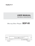
When the display assembly is open nearly 180 degrees, use a book or
something similar to support it. The angle of the display assembly with
respect to the bottom case should never exceed 180 degrees. Also, when
performing the procedures in this manual, the locations or directions relative to
the computer are as shown in Figure 1 unless otherwise specified.
back of computer
right side
left side
front of computer
)LJXUH&RPSXWHU2ULHQWDWLRQ
Dell Latitude CS Portable Computers Service Manual
1
5HFRPPHQGHG7RROV
Most of the procedures in this manual require the use of one or more of the
following tools:
#0 and #1 magnetized Phillips-head screwdrivers
Small flat-blade screwdriver
5-mm socket wrench
7-mm socket wrench
Small plastic scribe
3UHSDULQJWR:RUN,QVLGH<RXU&RPSXWHU
Before you start to work on the computer, perform the following steps:
1. Save any work in progress and close all open application programs.
2. Turn off the computer and any attached peripherals.
NOTE: Make sure that the computer is turned off and not in suspend-todisk mode (S2D). If you cannot shut down the computer using its operating
system, press the power button for 4 seconds.
3. If the computer is docked in a C/Dock Expansion Station or C/Port
Advanced Port Replicator (APR), undock the computer.
4. Disconnect the computer and any attached peripherals from their electrical
outlets to reduce the potential for personal injury or shock. Also disconnect
any telephone or telecommunications lines from the computer.
5. Remove the power cable.
6. Disconnect all other external cables from the computer.
7.
Remove any installed PC Cards.
127,&(0DNHVXUHWKDWWKHZRUNVXUIDFHLVFOHDQWRSUHYHQWVFUDWFK
LQJWKHFRPSXWHUFRYHU
127,&(7RDYRLGGDPDJLQJWKHV\VWHPERDUG\RXPXVWUHPRYHWKH
PDLQEDWWHU\EHIRUH\RXVHUYLFHWKHFRPSXWHU
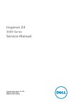
8. Turn the computer over so the battery is on the lower right corner of the
computer, and remove the main battery assembly from the battery bay.
Slide the battery bay latch toward the right side of the computer to push
the back side of the battery up out of the battery bay (seeFigure 2).
2
Dell Latitude CS Portable Computers Service Manual
battery
battery latch
)LJXUH0DLQ%DWWHU\$VVHPEO\5HPRYDO
9. Ground yourself by touching the unpainted metal surface of the I/O panel
on the back of the computer.
While you work, periodically touch the I/O panel to dissipate any static
electricity that might harm components.
6FUHZ,GHQWLILFDWLRQDQG7LJKWHQLQJ
The illustrations in the following removal procedures provide lengths of the
correct screws for each procedure. Figure 3 shows examples. Match the actual
screw to the illustration to check for correct length.
)LJXUH6FUHZ,GHQWLILFDWLRQ
127,&(:KHQUHLQVWDOOLQJDVFUHZ\RXPXVWXVHDVFUHZRIWKHFRU
UHFWOHQJWK2WKHUZLVH\RXFRXOGGDPDJHWKHKDUGZDUH0DNHVXUH
WKDWWKHVFUHZLVSURSHUO\DOLJQHGZLWKLWVFRUUHVSRQGLQJKROHDQG
DYRLGRYHUWLJKWHQLQJ
Dell Latitude CS Portable Computers Service Manual
3
When you are removing and replacing components, photocopy the Table 1
placement mat as a tool to lay out and keep track of the component screws.
7DEOH6FUHZ3ODFHPHQW0DWZLWK&RPSRQHQW6FUHZ&RXQWV
DQG6L]HV
Hard-Disk Drive
Assembly:
Memory Module
Cover:
M2 x 4 mm (2 each)
M2.6 x 3 mm (2 each)
Display Assembly,
including Bezel:
4
M2.6 x 6 mm (4 each)
Palmrest Assembly:
M2 x 4 mm (6 each
[Sharp LCD] and 8 each
[Samsung LCD])
Rubber Screw
Covers (2 each [large]
and 4 each [small])
M2 x 16 mm (2 each)
Thermal Cooling
Solution:
System Board
Assembly:
M2 x 13 mm (4 each)
M2 x 4 mm (3 each)
M2 x 4 mm (8 each)
M2.6 x 6 mm (2 each)
Media Bay Port:
Touch Pad:
M2 x 2.5 mm (2 each)
Display Assembly
Hinge to Bottom
Case Assembly:
Keyboard
Assembly:
M2 x 2.5 mm (2 each)
Dell Latitude CS Portable Computers Service Manual
M2 x 2.5 mm (2 each
[palmrest top])
M2 x 4 mm (7 each
[computer bottom])
M2 x 2.5 mm (5 each
[battery bay])
PC Card Cover:
M2 x 4 mm (4 each)
(part of system
board screws)
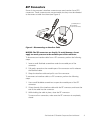
=,)&RQQHFWRUV
Some of the computers interface connectors are zero insertion force (ZIF)
connectors. These connectors are not removable, but they must be released
to disconnect a cable from them (see Figure 4).
movable part of
connector
(do not remove)
)LJXUH'LVFRQQHFWLQJDQ,QWHUIDFH&DEOH
127,&(7KH=,)FRQQHFWRUVDUHIUDJLOH7RDYRLGGDPDJHGRQRW
DSSO\WRRPXFKSUHVVXUHWRWKHPRYDEOHSDUWRIWKHFRQQHFWRU
To disconnect an interface cable from a ZIF connector, perform the following
steps:
1. Insert a small flat-blade screwdriver under the movable part of the
connector.
2. Pull gently upward on the movable part of the connector until it releases
the interface cable.
3. Grasp the interface cable and pull it out of the connector.
To reconnect an interface cable to a ZIF connector, perform the following
steps:
1. Use a small flat-blade screwdriver to open the movable part of the ZIF
connector.
2. Orient the end of the interface cable with the ZIF connector, and insert the
end of the cable into the connector.
3. While holding the cable in place, close the ZIF connector.
To ensure a firm connection, make sure the ZIF connector is completely
closed.
Dell Latitude CS Portable Computers Service Manual
5
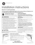
5HPRYLQJ)LHOG5HSODFHDEOH3DUWV
DQG $VVHPEOLHV
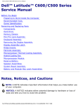
display
assembly
keyboard
left hinge cover
status indicator panel
palmrest
assembly
right hinge cover
thermal cooling
solution
system board
bottom case assembly
hard-disk drive
media-bay port cover
main battery
)LJXUH([SORGHG9LHZ³&RPSXWHU
The following subsections provide instructions for removing and replacing
field-replaceable parts and assemblies.
6
Dell Latitude CS Portable Computers Service Manual
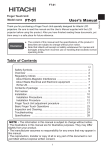
+DUG'LVN'ULYH$VVHPEO\
bottom of computer
M2 x 4-mm screw(2)
hard-disk drive door
)LJXUH+DUG'LVN'ULYH$VVHPEO\5HPRYDO
127,&(7RDYRLGGDPDJLQJWKHV\VWHPERDUG\RXPXVWUHPRYHWKH
PDLQEDWWHU\EHIRUH\RXVHUYLFHWKHFRPSXWHU
127,&(7KHKDUGGLVNGULYHLVYHU\VHQVLWLYHWRVKRFN+DQGOHWKH
DVVHPEO\E\LWVHGJHVGRQRWVTXHH]HWKHWRSRIWKHKDUGGLVNGULYH
FDVHDQGDYRLGGURSSLQJLW
127,&(0DNHVXUHWKDWWKHZRUNVXUIDFHLVFOHDQWRSUHYHQWVFUDWFK
LQJWKHFRPSXWHUFRYHU
1. Turn the computer over, and remove the two M2 x 4-mm screws from the
bottom of the hard-disk drive door (see Figure 6).
The drive is located on the left side of the computer when the computer is
turned over.
2. Grasp the drive door, slide it up, and pull the drive out of the computer.
0HPRU\0RGXOH&RYHU
127,&(7RDYRLGGDPDJLQJWKHV\VWHPERDUG\RXPXVWUHPRYHWKH
PDLQEDWWHU\EHIRUH\RXVHUYLFHWKHFRPSXWHU
127,&(0DNHVXUHWKDWWKHZRUNVXUIDFHLVFOHDQWRSUHYHQWVFUDWFK
LQJWKHFRPSXWHUFRYHU
1. Close the display, and turn the computer upside down on a flat work
surface.
2. Remove the two M2.6 x 3-mm screws from the memory module cover,
and lift the cover up and out (two tabs are located on the opposite side of
the screw holes on the cover).
Dell Latitude CS Portable Computers Service Manual
7
%RWWRP0HPRU\0RGXOH
memory module
memory
module
socket
inner tabs (2)
)LJXUH%RWWRP0HPRU\0RGXOH5HPRYDO
To remove the bottom memory module, perform the following steps.
127,&(7RDYRLGGDPDJLQJWKHV\VWHPERDUG\RXPXVWUHPRYHWKH
PDLQEDWWHU\EHIRUH\RXVHUYLFHWKHFRPSXWHU
127,&(7KH0%PHPRU\PRGXOHGRHVQRWILWLQWKHERWWRP
PHPRU\PRGXOHVRFNHW
1. Remove the memory module cover.
2. Ground yourself by touching the unpainted metal surface of an I/O
connector on the computers back panel.
3. To release the memory module from its socket, carefully spread apart
the inner tabs of the memory module socket just far enough for the
memory module to disengage from the socket (it should pop up slightly)
(see Figure 7).
4. Lift the memory module out of its socket.
To replace a memory module, perform the following steps:
1. Align the memory modules edge connector with the slot in the center of
the memory module socket.
Memory modules are keyed, or designed to fit into their sockets in only
one direction. The slots on the system board are notched so that the
memory module can be firmly seated only one way.
2. With the module at a 45-degree angle, press the memory modules edge
connector firmly into the memory module socket.
3. Pivot the memory module down until it clicks into place.
4. If you do not hear a click as each end of the memory module snaps into the
tabs, remove the memory module and reinstall it.
8
Dell Latitude CS Portable Computers Service Manual
7RS0HPRU\0RGXOH
memory module
inner tabs (2)
)LJXUH7RS0HPRU\0RGXOH5HPRYDO
127,&(7RDYRLGGDPDJLQJWKHV\VWHPERDUG\RXPXVWUHPRYHWKH
PDLQEDWWHU\EHIRUH\RXVHUYLFHWKHFRPSXWHU
1. Remove the status indicator panel.
Use a flat-blade screwdriver to press in on the three tabs that secure the
status indicator panel to the back panel of the computer (see Figure 9).
2. Remove the keyboard (see Figure 13).
3. Remove the thermal cooling solution (see Figure 18).
4. Ground yourself by touching the unpainted metal surface of an I/O
connector on the computers back panel.
5. To release the memory module from its socket, carefully spread apart
the inner tabs of the memory module socket just far enough for the
memory module to disengage from the socket (it should pop up slightly)
(see Figure 8).
Dell Latitude CS Portable Computers Service Manual
9
6. Lift the memory module out of its socket.
tabs (3)
)LJXUH6WDWXV,QGLFDWRU3DQHO5HPRYDO
To replace a memory module, perform the following steps.
127,&(7KH0%PHPRU\PRGXOHILWVWKHWRSPHPRU\PRGXOH
VRFNHWRQO\
1. Align the memory modules edge connector with the slot in the center of
the memory module socket.
Memory modules are keyed, or designed to fit into their sockets in only
one direction. The slots on the system board are notched so that the
memory module can be firmly seated only one way.
2. With the module at a 45-degree angle, press the memory modules edge
connector firmly into the memory module socket.
3. Pivot the memory module down until it clicks into place.
4. If you do not hear a click as each end of the memory module snaps into the
tabs, remove the memory module and reinstall it.
10
Dell Latitude CS Portable Computers Service Manual
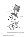
'LVSOD\$VVHPEO\
display assembly
M2.6 x 6-mm
screws (4)
display-assembly
interface wire
left hinge cover
display-assembly
inverter wire
status indicator
panel
right hinge cove
)LJXUH'LVSOD\$VVHPEO\5HPRYDO
127,&(7RDYRLGGDPDJLQJWKHV\VWHPERDUG\RXPXVWUHPRYHWKH
EDWWHU\EHIRUH\RXVHUYLFHWKHFRPSXWHU
1. Remove the status indicator panel.
2. Remove the right plastic hinge cover by sliding it to the right of the display
assembly.
3. Remove the two M2.6 x 6-mm hinge screws that secure the right hinge to
the bottom case (see Figure 10).
4. Remove the left plastic hinge cover by sliding it to the left of the display
assembly.
Dell Latitude CS Portable Computers Service Manual
11
5. Remove the two M2.6 x 6-mm hinge screws that secure the left hinge to
the bottom case.
6. Carefully disconnect the display-assembly interface wire connector,
located on the left side of the display assembly, from the system board.
The female connector attached to the display-assembly interface wire is
keyed to fit into the male connector one way only.
On some models, the interface wire is routed under the left hinge. To
remove the wire from under the hinge, remove all three M2 X 4-mm
screws attaching the left hinge to the display-assembly top cover (see Figure 11). For models that do not route the interface wire under the left
hinge, the wire is removed without removing the left hinge.
7.
Carefully disconnect the display-assembly inverter wire connector, located
on the right side of the display assembly, from the system board.
The female connector attached to the display-assembly inverter wire is
keyed to fit into the male connector one way only.
8. Lift the display assembly from the bottom assembly.
12
Dell Latitude CS Portable Computers Service Manual
'LVSOD\$VVHPEO\%H]HO
O
large rubber screw covers (2)
M2 x 4-mm screws (6)
display-assembly bezel
small rubber screw
covers (4)
latch
LCD panel
M2 x 4-mm
screws (6)
left hinge
inverter
display-assembly
interface wire
display-assembly top cover
display-assembly
inverter wire
right hinge
)LJXUH6KDUS'LVSOD\$VVHPEO\%H]HO5HPRYDO
127,&(7RDYRLGGDPDJLQJWKHV\VWHPERDUG\RXPXVWUHPRYHWKH
PDLQEDWWHU\EHIRUH\RXVHUYLFHWKHFRPSXWHU
1. Use a scribe to carefully pry the six rubber screw covers out of the six
screw holes located along the top and bottom of the bezel on the front of
the display assembly.
2. For a Sharp display-assembly bezel, remove the six M2 x 4-mm screws
located at the top and bottom of the bezel on the front of the display
assembly (see Figure 11). For a Samsung display-assembly bezel, remove
Dell Latitude CS Portable Computers Service Manual
13
O
large rubber screw covers (2)
M2 x 4-mm screws (8)
display-assembly bezel
LCD panel
small rubber screw
covers (4)
tabs (2)
Samsung
identification
notch
latch
notches (2)
M2 x 4-mm
screws (6)
left hinge
inverter
display-assembly
interface wire
display-assembly top cover
display-assembly
inverter wire
right hinge
)LJXUH6DPVXQJ'LVSOD\$VVHPEO\%H]HO5HPRYDO
the six M2 x 4-mm screws located at the top and bottom of the bezel on
the front of the display assembly (see Figure 12).
3. Separate the bezel from the display-assembly top cover.
The bezel is secured by slot openings that snap into the display-assembly
top cover. Lift the inside edge of the bezel, working your way around the
inside perimeter, to unsnap and remove it from the display assembly.
14
Dell Latitude CS Portable Computers Service Manual
127,&($PDJQHWLVPRXQWHGRQWKHEDFNVLGHRIWKHEH]HOEHKLQG
WKHOHIWKLQJHH[WHQVLRQFRYHU.HHSGLVNHWWHVDQGRWKHUPDJQHWLF
VWRUDJHPHGLDDZD\IURPWKLVDUHDWRDYRLGWKHSRWHQWLDOIRUGDWD
ORVV
'LVSOD\$VVHPEO\/DWFK
127,&(7RDYRLGGDPDJLQJWKHV\VWHPERDUG\RXPXVWUHPRYHWKH
PDLQEDWWHU\EHIRUH\RXVHUYLFHWKHFRPSXWHU
1. Remove the Sharp display-assembly bezel (seeFigure 11), or the Samsung
display-assembly bezel (see Figure 12).
2. Remove the display-assembly latch by sliding the latch from the inside of
the display-assembly bezel (see Figure 11).
/&'3DQHO
127,&(7RDYRLGGDPDJLQJWKHV\VWHPERDUG\RXPXVWUHPRYHWKH
PDLQEDWWHU\EHIRUH\RXVHUYLFHWKHFRPSXWHU
NOTE: This computer contains an LCD panel manufactured by Sharp or Samsung. The display-assembly bezel and the display-assembly top cover are
unique for each manufacturers LCD panel. When viewed from the back of the
computer, there is a notch on the lower-right corner of the hinged edge of the
Samsung display assembly (see Figure 12). Close the LCD display assembly
and view the back of the computer to identify the Samsung notch.
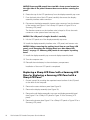
5HSODFLQJD6KDUS/&'SDQHOZLWKD6KDUS/&'
SDQHORU5HSODFLQJD6DPVXQJ/&'SDQHOZLWKD
6DPVXQJ/&'SDQHO
1. Ground yourself by touching the unpainted metal surface of the I/O panel
on the back of the computer.
2. Remove the status indicator panel (see Figure 9).
3. Remove the display assembly (see Figure 10).
4. Remove the display assembly bezel (see Figure 11 for a Sharp LCD panel or
Figure 12 for a Samsung LCD panel).
5. Remove the inverter (see Figure 11 for a Sharp LCD panel or Figure 12 for a
Samsung LCD panel).
If you have a Sharp or Samsung LCD panel, the inverter is held in place by
two plastic clips located at the top and bottom of the inverter. Press down
on the top of the inverter, and then rotating the top up and slide the
inverter out of the bottom clip.
Dell Latitude CS Portable Computers Service Manual
15
127,&(6DPVXQJ/&'SDQHOVKDYHWZR0[PPVFUHZVORFDWHGRQ
WKHULJKWVLGHRIWKHSDQHO5HPRYHWKHVHVFUHZVEHIRUHURWDWLQJWKH
SDQHO
6. Rotate the top of the LCD panel away from the display-assembly top cover.
7.
From the back side of the LCD panel, carefully disconnect the displayassembly interface cable connector.
8. Disconnect the display-assembly inverter wire connector from the bottom
of the inverter (see Figure 11 for a Sharp LCD panel or Figure 12 for a
Samsung LCD panel).
The female connector on the interface wire is keyed to fit into the male
connector on the system board one way only.
127,&(7KH/&'SDQHOLVIUDJLOH+DQGOHLWFDUHIXOO\
9. Lift the LCD panel out of the display-assembly top cover.
10. Install the display-assembly interface wire, LCD panel, and inverter wire.
127,&(%HIRUHUHPRYLQJWKHSDFNLQJEH]HOIURPDQHZ6KDUS/&'
SDQHOUHDG´5HPRYLQJWKH3DFNLQJ%H]HORQD1HZ6KDUS/&'
3DQHOµRQSDJH 6DPVXQJ/&'SDQHOVGRQRWUHTXLUHDSDFNLQJ
EH]HO
11. Install the display-assembly top cover and display-assembly bezel.
12. Turn the computer over.
13. Reinstall the main battery in the main battery compartment.
Installation of the new LCD panel is completed.
5HSODFLQJD6KDUS/&'3DQHOZLWKD6DPVXQJ/&'
3DQHORU5HSODFLQJD6DPVXQJ/&'3DQHOZLWKD
6KDUS/&'3DQHO
1. Ground yourself by touching the unpainted metal surface of the I/O panel
on the back of the computer.
2. Remove the status indicator panel (see Figure 9).
3. Remove the display assembly (see Figure 10).
4. Remove the old display-assembly top cover and display-assembly bezel
(see Figure 11 for a Sharp LCD panel or Figure 12 for a Samsung LCD
panel).
5. Remove the inverter (see Figure 11 for a Sharp LCD panel or Figure 12 for a
Samsung LCD panel).
16
Dell Latitude CS Portable Computers Service Manual
If you have a Sharp or Samsung LCD panel, the inverter is held in place by
two plastic clips located at the top and bottom of the inverter. Press down
on the top of the inverter, and then rotating the top up and slide the
inverter out of the bottom clip.
6. Remove the old display-assembly interface wire, LCD panel, and displayassembly inverter wire.
127,&(7KH/&'SDQHOLVIUDJLOH+DQGOHLWFDUHIXOO\
NOTE: A new display-assembly top cover, inverter, inverter wire, and bezel are
supplied in the service kit.
127,&(%HIRUHUHPRYLQJWKHSDFNLQJEH]HOIURPDQHZ6KDUS/&'
SDQHOUHDG´5HPRYLQJWKH3DFNLQJ%H]HORQD1HZ6KDUS/&'
3DQHOµ6DPVXQJ/&'SDQHOVGRQRWUHTXLUHDSDFNLQJEH]HO
7.
Install the new display-assembly interface wire, LCD panel, and inverter
wire into the new top cover provided in the service kit.
8. Attach the new bezel to the display assembly.
9. Turn the computer over.
10. Reinstall the main battery in the main battery compartment.
Installation of the new LCD panel is completed.
5HPRYLQJWKH3DFNLQJ%H]HORQD1HZ6KDUS/&'3DQHO
New Sharp LCD panels are shipped with a packing bezel to provide support
and prevent damage. Prepare the new Sharp LCD panel for installation in the
display assembly by performing the following steps:
1. Carefully peel the protective laminate film off of the LCD panel.
2. Remove the top-half of the packing bezel.
127,&(7KH/&'SDQHOLVIUDJLOH+DQGOHLWFDUHIXOO\
3. Pull the bezel out from the LCD panel near the hook locations to release
the LCD panel from the bottom half of the packing bezel.
The bottom-half of the packing bezel holds the LCD panel in place with six
hooks (two located on the top left, two located on the top right, and one
located on each side approximately two-thirds up the length of each side).
3DFNLQJD'HIHFWLYH6KDUS/&'3DQHOIRU5HWXUQ6KLSSLQJ
To assemble the Sharp LCD panel and packing bezel for return shipment,
perform the following steps:
1. Place the LCD panel in to the bottom-half of the packing bezel.
2. Place the top-half of the packing bezel on the LCD panel.
Dell Latitude CS Portable Computers Service Manual
17
3. Make sure that the six hooks on the shipping bezel hold the LCD panel
firmly in place behind.
.H\ERDUG$VVHPEO\
M2 x 16-mm black screws 2)
(
keyboard
assembly
)LJXUH5HPRYLQJWKH.H\ERDUG$VVHPEO\6FUHZV
To remove the keyboard assembly, perform the following steps.
127,&(7RDYRLGGDPDJLQJWKHV\VWHPERDUG\RXPXVWUHPRYHWKH
PDLQEDWWHU\EHIRUH\RXVHUYLFHWKHFRPSXWHU
127,&(0DNHVXUHWKDWWKHZRUNVXUIDFHLVFOHDQWRSUHYHQW
VFUDWFKLQJWKHFRPSXWHUFRYHU
1. Remove the status indicator panel (see Figure 9).
2. Remove the two black M2 x 16-mm screws located at the top of the
keyboard (see Figure 13).
3. Carefully disconnect the keyboard cable connector from the system board.
127,&(7KHNH\FDSVRQWKHNH\ERDUGDUHIUDJLOHHDVLO\GLVORGJHG
DQGWLPHFRQVXPLQJWRUHSODFH%HFDUHIXOZKHQUHPRYLQJDQG
KDQGOLQJWKHNH\ERDUG
4. Release the keyboard from the palmrest assembly by lifting the top edge
of the keyboard up and sliding it toward the back of the computer.
18
Dell Latitude CS Portable Computers Service Manual
NOTE: Five metal tabs retain the bottom of the keyboard in the palmrest
assembly.
5. Remove the keyboard assembly (see Figure 13).
To replace the keyboard assembly, perform the following steps.
127,&(3RVLWLRQWKHNH\ERDUGFDEOHVRLWLVQRWWZLVWHGZKHQFRQ
QHFWHGWRWKHV\VWHPERDUG
1. Connect the keyboard cable to the connector on the system board.
2. Fit the keyboard into place by sliding the five tabs on the bottom of the
keyboard into the palmrest assembly.
3. Press on the upper left and right edges of the keyboard to snap the upper
tabs into the palmrest.
4. Verify that the keyboard is correctly installed.
The keys should be flush with the left and right surfaces of the palmrest.
5. Reinstall the two black M2 x 16-mm screws.
6. Snap the status indicator panel in place.
3DOPUHVW$VVHPEO\
M2 x 4-mm screws (7)
M2 x 2.5-mm screws (5)
)LJXUH5HPRYLQJWKH3DOPUHVW$VVHPEO\6FUHZV
The palmrest assembly consists of the palmrest, speaker, microphone, and
power button with spring.
Dell Latitude CS Portable Computers Service Manual
19
127,&(7RDYRLGGDPDJLQJWKHV\VWHPERDUG\RXPXVWUHPRYHWKH
PDLQEDWWHU\EHIRUH\RXVHUYLFHWKHFRPSXWHU
1. Remove the display assembly (see Figure 10).
2. Remove the keyboard (see Figure 13).
3. Remove the two M2 x 2.5-mm screws located at the top of the palmrest
assembly (see Figure 15).
127,&(0DNHVXUHWKDWWKHZRUNVXUIDFHLVFOHDQWRSUHYHQW
VFUDWFKLQJWKHFRPSXWHUFRYHU
4. Turn the computer upside down on a flat work surface.
5. Remove the seven M2 x 4-mm screws that secure the palmrest to the
computer.
These screws are located along the left and right sides on the bottom of
the computer (see Figure 14).
6. Remove the five M2 x 2.5-mm screws located in the main battery
compartment (see Figure 14).
7.
Turn the computer right-side up on the work surface.
8. Lift the front of the palmrest assembly up and rotate it to a 90-degree angle
from the bottom assembly.
9. Carefully disconnect the microphone and speaker connectors from the
system board (the microphone and speaker connections are located on the
back right-hand corner of the system board).
NOTE: The female connectors are keyed to fit into the male connectors one
way only. Also, the microphone and speaker connectors are keyed to fit their
specific connectors only.
10. Carefully remove the palmrest assembly from the bottom assembly (see
Figure 15).
20
Dell Latitude CS Portable Computers Service Manual
M2 x 2.5-mm screws (2
palmrest assembly
)LJXUH3DOPUHVW$VVHPEO\5HPRYDO
Dell Latitude CS Portable Computers Service Manual
21
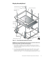
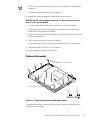
%RWWRP$VVHPEO\
thermal cooling
solution
fan
assembly
main battery release
latch location
system board
assembly
main battery
compartment
reserve
battery
touch pad
bottom
case cover
)LJXUH%RWWRP$VVHPEO\
The bottom assembly consists of the following field-replaceable components:
Reserve battery
Main battery
Main battery release latch
Thermal cooling solution
System board assembly
Fan assembly
Touch pad
Bottom case cover
5HVHUYH%DWWHU\
127,&(7KHUHVHUYHEDWWHU\SURYLGHVSRZHUWRWKHFRPSXWHU·VUHDO
WLPHFORFN57&DQGQRQYRODWLOHUDQGRPDFFHVVPHPRU\195$0
ZKHQWKHFRPSXWHULVWXUQHGRII5HPRYLQJWKHEDWWHU\FDXVHVWKH
FRPSXWHUWRORVHLWVGDWHDQGWLPHLQIRUPDWLRQDVZHOODVDOOXVHU
VHWWDEOHSDUDPHWHUVLQ195$0,ISRVVLEOHPDNHDFRS\RIWKLV
LQIRUPDWLRQEHIRUH\RXUHPRYHWKHUHVHUYHEDWWHU\
1. Remove the status indicator panel (see Figure 9).
2. Remove the keyboard (see Figure 13).
22
Dell Latitude CS Portable Computers Service Manual
3. Disconnect the reserve battery cable from the connector on the system
board and lift the reserve battery (see Figure 16).
The reserve battery is located behind the hard-disk drive, and is attached to
the system board with an adhesive foam pad.
4. Tear the reserve battery free from the foam pad.
5. Remove the remnants of the foam pad from the system board.
0DLQ%DWWHU\
See the Preparing to Work Inside Your Computer section found earlier in this
manual for detailed instructions for removing the battery.
0DLQ%DWWHU\5HOHDVH/DWFK
touch pad cable
tension spring
release button assembly
main battery release latch
)LJXUH 0DLQ%DWWHU\5HOHDVH/DWFK
1. Remove the status indicator panel (see Figure 9).
2. Remove the display assembly (see Figure 10).
3. Remove the keyboard assembly (see Figure 13).
4. Remove the palmrest assembly (see Figure 14).
5. Remove the thermal cooling solution (see Figure 18).
6. Carefully disconnect the touch pad cable from the ZIF connector on the
system board (see Figure 4 and Figure 17).
Dell Latitude CS Portable Computers Service Manual
23
7.
Grasp the top of the battery release latch and gently pull up to free it from
the release button assembly, which is located underneath the system
board (see Figure 17).
The battery release latch is mounted on the back side of the battery
compartment next to the system board assembly.
127,&(:KHQUHLQVWDOOLQJWKHEDWWHU\UHOHDVHODWFKFRQQHFWWKH
WRXFKSDGFDEOHWRWKH=,)FRQQHFWRURQWKHV\VWHPERDUGDIWHU
LQVWDOOLQJWKHEDWWHU\UHOHDVHODWFK
8. Unhook the small tension spring from the metal post to remove the battery
release latch.
The spring attaches the right end of the battery release latch to a small
metal post located next to the hard-disk drive.
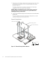
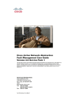
7KHUPDO&RROLQJ6ROXWLRQ
M2 X 13-mm screws (4)
thermal cooling solution
M2 X 4-mm screws (3)
)LJXUH7KHUPDO&RROLQJ6ROXWLRQ5HPRYDO
24
Dell Latitude CS Portable Computers Service Manual
127,&(7RDYRLGGDPDJLQJWKHV\VWHPERDUG\RXPXVWUHPRYHWKH
PDLQEDWWHU\EHIRUH\RXVHUYLFHWKHFRPSXWHU
NOTE: The thermal cooling solution screw holes are labeled with screw sizes
and numbered for the order that the screws should be removed or installed.
1. Remove the keyboard assembly (see Figure 13).
2. Remove the four M2 x 13-mm screws grouped around the section of the
thermal cooling solution that covers the microprocessor (see Figure 18).
The screw holes are labeled on the thermal cooling solution in the order
that the screws should be removed (1 through 4).
3. Remove the three M2 x 4-mm screws in the corners of the thermal cooling
solution.
The screw holes are labeled on the thermal cooling solution in the order
that the screws should be removed (5 through 7).
127,&(7RHQVXUHPD[LPXPFRROLQJIRUWKHPLFURSURFHVVRUGRQRW
WRXFKWKHKHDWWUDQVIHUDUHDVRQWKHWKHUPDOFRROLQJVROXWLRQ7KH
RLOVLQ\RXUVNLQUHGXFHWKHKHDWWUDQVIHUFDSDELOLW\RIWKHWKHUPDO
SDGV
Dell Latitude CS Portable Computers Service Manual
25
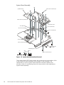
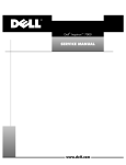
6\VWHP%RDUG$VVHPEO\
system board
M2 X 4-mm screws (8)
M2.6 X 6-mm screws (2)
PC Card cover
fan assembly
7-mm sockets (2)
fan wire connector
5-mm sockets (4)
touch pad
M2 X 2.5 screws (2)
media-bay port cover
media-bay port
screws (2)
M2 X 2.5 screws (2)
)LJXUH6\VWHP%RDUG$VVHPEO\5HPRYDO
The system boards BIOS chip contains the system service tag number, which
is also visible on a bar-code label on the bottom of the computer. The
replacement kit for the system board assembly includes a diskette that
provides a utility for transferring the service tag number to the replacement
system board assembly.
26
Dell Latitude CS Portable Computers Service Manual
To remove the system board assembly, perform the following steps.
127,&(7RDYRLGGDPDJLQJWKHV\VWHPERDUG\RXPXVWUHPRYHWKH
PDLQEDWWHU\EHIRUH\RXVHUYLFHWKHFRPSXWHU
1. Remove the palmrest assembly (see Figure 15).
2. Remove the thermal cooling solution (see Figure 18).
127,&(7RHQVXUHPD[LPXPFRROLQJIRUWKHPLFURSURFHVVRUGRQRW
WRXFKWKHKHDWWUDQVIHUDUHDVRQWKHWKHUPDOFRROLQJDVVHPEO\7KH
RLOVLQ\RXUVNLQUHGXFHWKHKHDWWUDQVIHUFDSDELOLW\RIWKHWKHUPDO
SDGV
3. Remove the media-bay port cover from the bottom assembly by removing
the two M2 x 2.5 screws from the bottom of the media-bay port cover and
removing the two media-bay port screws (see Figure 19).
4. Remove the main battery release latch (see Figure 17).
5. Use a 5-mm socket wrench to remove the four 5-mm sockets for the VGA
and parallel ports located on the back of the bottom assembly.
6. Use a 7-mm socket wrench to remove the two 7-mm sockets for the
docking connector located on the back of the bottom assembly (or use a
flat-blade screwdriver to remove these 7-mm sockets).
7.
Remove the eight M2 x 4-mm screws connecting the system board to the
bottom assembly.
These eight M2 x 4-mm screws are marked with white circles around the
screw head on the system board.
8. Remove the two M2.6 x 6-mm screws connecting the system board to the
bottom assembly.
These two M2.6 x 6-mm screws are marked with white circles around the
screw head on the system board.
9. Remove any PC Cards or plastic blanks from the PC Card slot.
10. Verify that the PC Card ejectors do not extend from the PC Card slot.
11. Carefully disconnect the fan wire connector from the system board (see
Figure 19).
The female connector on the fan wire is keyed to fit into the male
connector one way only.
12. Lift the system board assembly out of the bottom assembly.
13. Transfer the memory module(s) to the replacement system board
assembly.
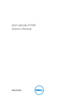
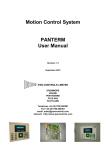
14. Remove the microprocessor. The microprocessor socket is either type A or
type B (see Figure 20).
Dell Latitude CS Portable Computers Service Manual
27
If the socket is type A, use a flat-blade screwdriver to turn the cam
180 degrees counterclockwise. When the cam is in the open position, the
triangular-shaped pointer on the cam points toward the O (open
position), and a view window, on the lower right-hand side of the cam,
displays a full circle (see Figure 20, type-A socket). Grasp the edges of the
microprocessor to lift it out of the socket.
If the socket is type B, use a Phillips-head or a flat-blade screwdriver to turn
the cam 180 degrees counterclockwise. When the cam is in the open
position, a tab on the cam points toward the O (open position) (see
Figure 20, type-B socket). Grasp the edges of the microprocessor to lift it
out of the socket.
127,&(7KHPLFURSURFHVVRUGLHWKHSXUSOHUHFWDQJXODUDUHDPXVW
UHPDLQIUHHRIDQ\VFUDWFKHVGXVWUHVLGXHDQGILQJHUSULQWV
127,&('RQRWWRXFKWKHPLFURSURFHVVRUGLHRUWKHPLFURSURFHVVRU
SLQV3LFNXSWKHPLFURSURFHVVRUE\WKHHGJHVWRXFKLQJRQO\WKH
EURZQSHULPHWHUDUHDVXUURXQGLQJWKHGLH
127,&('RQRWGURSWKHPLFURSURFHVVRUIURPDGLVWDQFHRIPRUH
WKDQLQFKHVDQGGRQRWEHQGWKHPLFURSURFHVVRUSLQV5HSODFHWKH
PLFURSURFHVVRULILWLVGURSSHGIURPDGLVWDQFHRIPRUHWKDQLQFKHV
RULIWKHSLQVDUHEHQWPRUHWKDQGHJUHHV
15. Remove the two M2 x 4-mm screws located on the back corners of the
hard-disk drive bay that attach the hard-disk drive electromagnetic
interference (EMI) clips to the system board.
16. Install a new microprocessor.
To install a microprocessor in a type-A socket, place the microprocessor in
the socket and use a flat-blade screwdriver to turn the triangular-shaped
pointer on the cam clockwise 180 degrees toward the L (locked
position). The view window displays a half circle when the cam is in the
locked position (see Figure 20, type-A socket).
To install a microprocessor in a type-B socket, place the microprocessor in
the socket and use a Phillips-head or flat-blade screwdriver to turn the cam
clockwise 180 degrees so that the tab on the cam points toward the C
(closed position) (see Figure 20, type-B socket).
NOTE: When replacing the microprocessor, save the package material from
the new microprocessor to repackage the old microprocessor for transport.
17. Attach the hard-disk drive EMI clips and the PC Card cover to the new
system board assembly.
After replacing the system board assembly, be sure to enter the systems
service tag number into the BIOS of the replacement system board assembly.
Insert the diskette that accompanied the replacement system board assembly
into the diskette drive, and turn on the computer. Follow the instructions on the
display screen.
28
Dell Latitude CS Portable Computers Service Manual
open position
microprocessor
view window
socket
type-A socket
open position
microprocessor
socket
type-B socket
)LJXUH0LFURSURFHVVRU5HPRYDO
7RXFK3DG
1. Remove the palmrest assembly (see Figure 15).
2. Remove the two M2 x 2.5-mm screws from the top of the touch pad (see
Figure 19).
3. Carefully disconnect the ZIF connector to release the touch pad cable from
the system board (refer to Figure 4).
4. Remove the touch pad.
)DQ$VVHPEO\
1. Remove the palmrest assembly (see Figure 15).
2. Remove the thermal cooling solution (see Figure 18).
3. Carefully disconnect the fan wire connector from the system board (see
Figure 19).
Dell Latitude CS Portable Computers Service Manual
29
The female connector on the fan wire is keyed to fit into the male
connector one way only.
4. Remove the two M2 x 4-mm screws that secure the fan assembly to the
bottom assembly.
30
Dell Latitude CS Portable Computers Service Manual
,QGH[
%
/
bottom assembly
components, 22
illustrated, 22
LCD panel removal, 15
0
'
display assembly
bezel removal, 13, 14
removal, 11
)
fan removal, 29
field-replaceable parts and
assemblies illustrated, 6
*
grounding to dissipate static
electricity, 3
main battery
release latch removal, 23
removal, 3, 23
memory module
cover removal, 8
removal, 8
microprocessor removal, 29
3
palmrest assembly
removal, 21
screws removal, 19
5
reserve battery removal, 22
+
hard-disk drive assembly removal, 7
6
screw identification and tightening, 3
.
sockets
memory module, 8
keyboard assembly removal, 18
status indicator panel removal, 10
system board assembly
Index
31
illustration, 26
removal, 26
7
thermal cooling solution removal, 24
tools, 2
top memory module removal, 9
touch pad removal, 29
32
Dell Latitude CS Portable Computers Service Manual
=
ZIF connectors, 5
3ULQWHGLQ,UHODQG
(
ZZZGHOOFRP
3155HY$
3ULQWHGLQWKH86$
(
ZZZGHOOFRP
3155HY$