1
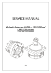
SERVICE MANUAL
Hydraulic Brakes type LB/288…, LBS[V]/289 and
LBS[V]/290 - series 4
Euro and SAE versions
2008
Service Manual
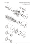
Hydraulic Brake type LB/288…
-2-
Service Manual
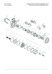
Hydraulic Brake type LBS[V]/289…
-3-
Service Manual
Hydraulic Brake type LBS[V]/290…
-4-
Service Manual
Disassembly
Hydraulic Brake type LB/288…,
LBS[V]/289… and LBS[V]/290…
Instructions in this manual are for brakes type
LB…
Cleanliness is extremely important when
repairing these brakes. Work in clean area!
Before disassembly, drain oil from brake.
If there is castellated nut, washer or key, they
have to be removed from the shaft.
Although not all drawings show the brakes in
disassembly devise, we recommend that you
keep brake clamped during disassembly.
For LBS[V]/289 and LBS[V]/290:
Fig. 2
1. Unscrew plugs (3 pcs. for LB/288 and
LBS, 4 pcs. for LBV) using S6 Allen head
spanner and set them in order aside incl. seals.
4. Remove piston from housing. Use special
tool with two screws M5x20 screwed in M5
holes to rest in advance and using a puller. Take
the O-rings and the Back up rings out of piston
and bushing grooves. The piston will come out
with inner rim of bearing, adjustment washer and
dick springs (see Fig.2).
5. Remove from housing groove O-ring
114,2х1,78.
Fig.1
2. Place the brake in disassembly devise
(plate with central hole ø83 for LB/288, 289 or
ø125 (ø127) for LBS(LBV)/290 with two pins
opposite staved into it) with the output shaft
directed downwards. Unscrew screws (8 pcs.)
using Allen head spanner.
Fig. 3
6. Take the O-ring 109,5х3 and the Back up
ring 109х114,2х1,4 out of housing groove (see
Fig.3).
Note: Unscrew the screws uniformly,
diametrically, successively to prevent breaking
the screw heads in result of the spring pressure.
Remove flange incl. shaft seal and outer rim
of bearing (see Fig. 1).
7. Remove bushing carefully out of the brake
housing using a puller with slight swivelling
motions. Remove from bushing groove O-ring
71х3 and Back up ring 71х76,2х1,4.
3. Remove from flange shaft seal. Do not
dismount outer rim of bearing from flange.
8. Take the O-ring 109,5х3 and the Back up
ring 109х114,2х1,4 out of housing groove (see
Fig.3).
-5-
Service Manual
Disassembly
Hydraulic Brake type LB/288…,
LBS[V]/289… and LBS[V]/290…
9. Remove from housing whole assembly
contained shaft, inner rims of front ant rear
bearings, steel disks, sinter disks and support
rings (see Fig.4). Separate the rims from shaft.
Check the friction elements for defects
(availability of wearing marks and checking the
weight) and replace with new ones.
1. CLEANING:
Wash all parts (except seals) in a weak
solvent on carbon base and then degrease.
2. MEASURING AND REPLACEMENT:
Measure all parts and compare their actual
dimensions with the nominal ones given in the
technical documentation. Replace any parts
with scratches or burrs that could cause leakage
or damage with new ones. Use new seals and
washers when reassembling the motor.
3. LUBRICATION:
Lubricate all friction parts, which should
be reassembled with light film of petroleum
jelly.
Fig.4
10. With a small screwdriver remove dust
seal from housing.
Knock the shaft seal out of housing using a
soft bushing and a plastic hammer (see Fig. 5).
Do not remove ftom housing outer bearing rim!
Fig. 5
Seal Kits:
Euro version
SK 41 5127 8032 for LB/288-series 4
SK 41 5127 8000 for LBS[V]/289 and LBS[V]/290
- series 4
SAE version
SK 41 5128 9500 for LB/288 - series 4
SK 41 5128 9544 for LBS/289 and LBS/290 series 4
SK 41 5128 9619 for LBV/289 and LBV/290 series 4
-6-
Service Manual
Reassembly
1. Place lubricated shaft seal (5 bar) in the
housing and firmly push with Seal driver (see
Fig.6).
Hydraulic Brake type LB/288…,
LBS[V]/289… and LBS[V]/290…
9. Mount lubricated O-ring 71х3 with back up
ring 71х76,2х1,4 into bushing grooves. (see
Fig.7)
Fig.6
2. If dismounted, stave the outer bearing
rim of the front tapered bearing into the housing
(with the bigger diameter orientated to the
housing) using a bushing made from nonferrous metal (bronze, brass) and sizes
ø55xø61x50 and a 2000daN press. Fix the
housing in reassembly devise (plate with an ø83
hole for LBS[V]/289 or ø125 (ø127) for
LBS[V]/290 and two pins on ø106).
Fig.7
10. Assemble together the lubricated piston
and bushing. Mount assembly in brake housing
using a hand-power press with guaranteed
rectilinear movement.
3. Stave to the rest over the front part of
shaft the inner bearing race and the roller
retaining ring of the front tapered roller bearing.
Use a small press and an ø36xø42x90 bushing.
Arrange correct the sinter disks beginning and
finishing with the steel disk and engaging the
sinter disks inner teeth with the shaft outer teeth.
Place support disks over friction pack. See
Table 1 for correct number of disks.
Place a slightly oiled safety metal cap (for
protecting the shaft seal ring lips) on the
assembled shaft. Mount carefully the shaft
assembly into the housing to the rest!
ATTENTION: Before mounting grease
well each friction dick. The external 3 teeth of
all steel disks should coincide with the grooves
milled in the housing!
4. Mount lubricated O-ring 109х114,2х1,4
(2 pcs.) with back up ring 109,5х3 (2 pcs.) into
housing grooves. (see fig.7)
ATTENTION: Orient O-ring to the arch
sector of back-up ring.
Fig.8
11. Install adjustment washer and disk springs
(see Fig. 8).
IMPORTANT! The size of adjustment washer
should ensure opening pressure as shown in Table
1 (after mounting of flange the dimension over
disk springs should be 9±0,1 mm) (see Fig.8).
12. On rear part of shaft stave the inner
bearing race of the rear bearing incl. the roller
retaining ring. Outer rim is staved in flange.
13. Lubricate and install O-ring 114,2х1,78 in
the housing seal groove.
-7-
Service Manual
Reassembly
Hydraulic Brake type LB/288…,
LBS[V]/289… and LBS[V]/290…
14. Lubricate slightly the internal surface of
the flange and orient it as follows:
2. Separate O-ring 82x2 from flange (see
Fig.9). There are no rear bearing and shaft seal.
- drain port in flange should be rotated 110
left of release port in housing (see Fig.1).
- line up the bolt holes of housing and
flange.
3. After dismounting of piston and bushing
turn the brake unit with open side downwards.
Shake it slightly on soft surface. Support rings,
sinter disks and steel disks will drop out.
15. Mount flange to housing with 8 screws
М8 and alternately torque them to 2,5÷3,0
daNm using S6 Allen head spanner (see Fig.1).
4. Reposition brake with output shaft up.
ATTENTION: The axial clearance
between front and rear tapered bearing should
be 0,04±0,1 mm. It can be realized by
decreasing the flange thickness.
16. Install seal on plug and torque to 2,5÷3,0
daNm using S6 Allen head spanner (see Fig.1).
For LBS plugs are 3 pcs. and for LBV – 4 pcs.
17. Lubricate flange seal groove and
external surface of shaft. Place lubricated shaft
seal (high pressure) in the flange and firmly
push with Seal driver.
18. Reposition brake assembly with output
shaft up. Lubricate dust seal and install in
housing seal groove.
19. Install key in shaft key groove. For cone
shafts install washer and screw castellated nut.
Fig. 10
Remove from housing shaft seal (see Fig.10).
Remove the retaining rings using utility pliers
for holes and shaft.
5. Place the brake in disassembly devise
(plate with central hole ø83 with two pins
opposite staved into it) with the output shaft
directed downwards. Separate shaft from housing
using a small press. Remove bearing from shaft.
Disassembly and reassembly of LB/288:
Follow the same disassembly and
reassembly procedures as for LBS[V]/289 and
LBS[V]/290 except following:
Disassembly:
1. The plugs are mounted in housing, not in
flange.
Reassembly:
6. Using a small press and bushing made from
non-ferrous metal (bronze, brass) stave to rest the
radial bearing over the front part of shaft.
Mount the retaining ring in shaft in front of
the bearing (see Fig.10).
7. With a small press sstave the assembled
shaft in front part of the housing. Mount the
retaining ring in housing (in front of the bearing).
Note: The retaining rings are correct mounted
when could be rotated over shaft axes.
Fig. 9
8. Place a safety cap over the shaft journal to
protect the seal lips against breaking. With seal
driver stave in the housing shaft seal (see Fig.11).
-8-
Service Manual
Reassembly
Hydraulic Brake type LB/288…,
LBS[V]/289… and LBS[V]/290…
9. Turn the housing and place it in an
assembling fixture (plate with a central hole ø83
and two pins of ø106 diametrically). Arrange the
steel and sinter disks successively in the housing
along the shaft teeth.
10. After mounting the flange to housing
insert lubricated O-ring 82х2 into flange seal
groove and place face seal to protect flange
surface.
Fig. 11
ATTENTION:
1. ** In all brakes, friction disks and separators should be lubricated. Space is filled with 50 ÷
120 cm3 mineral oil HLP (DIN 51524) or HM (ISO 6743/4).
2. Hydraulic brake is delivered without oil (it is lubricated only).
** For LB/288 fill oil after hydraulic motor assembly.
Table 1
Brake type
Steel
disk
Sinter
disk
Support
ring
Opening Pressure
Static torque
min
max
PSI [bar]
in.-lb. [daNm]
58÷116
4350
531÷708
[4÷8]
[300]
[6÷8]
116÷232 4350
1150÷1327
[8÷16]
[300]
[13÷15]
LB/288-7
3
2
4
LB/288-14
3
2
4
3
2
4
246÷333
[17÷23]
4350
[300]
1770÷1947
[20÷22]
4
3
3
246÷333
[17÷23]
4350
[300]
2743÷3009
[31÷34]
5
4
2
246÷333
[17÷23]
4350
[300]
3628÷3982
[41÷45]
7
6
-
246÷333
[17÷23]
4350
[300]
5310÷5753
[60÷65]
LB/288-21
LBS/289-21
LBS/290-21
LB/288-32
LBS/289-32
LBS/290-32
LB/288-43
LBS/289-43
LBS/290-43
LB/288-63
LBS/289-63
LBS/290-63
-9-