1
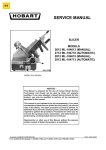
SERVICE MANUAL
SUPPLEMENT
MODEL 2912SC (AUTOMATIC)
SLICE COUNT SLICER
ML-104832
This Service Manual Supplement should be used with
Service Manual Form 24569 02-98.
- NOTICE This Manual is prepared for the use of trained Hobart Service
Technicians and should not be used by those not properly
qualified. If you have attended a Hobart Service School for this
product, you may be qualified to perform all the procedures
described in this manual.
This manual is not intended to be all encompassing. If you have
not attended a Hobart Service School for this product, you should
read, in its entirety, the repair procedure you wish to perform to
determine if you have the necessary tools, instruments and skills
required to perform the procedure. Procedures for which you do
not have the necessary tools, instruments and skills should be
performed by a trained Hobart Service Technician.
Reproduction or other use of this Manual, without the express
written consent of Hobart Corporation, is prohibited.
A product of Hobart Corporation
Form 24642 (MARCH 1999)
Troy, Ohio 45374
MODEL 2912SC SLICER GENERAL
TABLE OF CONTENTS
GENERAL . . . . . . . . . . . . . . . . . . . . . . . . . . . . . . . . . . . . . . . . . . . . . . . . . . . . . . . . . . . . . . . . . . . . . . . . . . . . .
Operation . . . . . . . . . . . . . . . . . . . . . . . . . . . . . . . . . . . . . . . . . . . . . . . . . . . . . . . . . . . . . . . . . . . . .
Service Information . . . . . . . . . . . . . . . . . . . . . . . . . . . . . . . . . . . . . . . . . . . . . . . . . . . . . . . . . . . . . .
Tools . . . . . . . . . . . . . . . . . . . . . . . . . . . . . . . . . . . . . . . . . . . . . . . . . . . . . . . . . . . . . . . . . . . . . . . . .
3
3
3
3
REMOVAL AND REPLACEMENT OF PARTS . . . . . . . . . . . . . . . . . . . . . . . . . . . . . . . . . . . . . . . . . . . . . . . . .
Slice Count Keypad or Bezel . . . . . . . . . . . . . . . . . . . . . . . . . . . . . . . . . . . . . . . . . . . . . . . . . . . . . . .
Slice Switch (3LS) . . . . . . . . . . . . . . . . . . . . . . . . . . . . . . . . . . . . . . . . . . . . . . . . . . . . . . . . . . . . . . .
Slicer Control Board . . . . . . . . . . . . . . . . . . . . . . . . . . . . . . . . . . . . . . . . . . . . . . . . . . . . . . . . . . . . .
Motor Control Board . . . . . . . . . . . . . . . . . . . . . . . . . . . . . . . . . . . . . . . . . . . . . . . . . . . . . . . . . . . . .
4
4
5
6
6
SERVICE PROCEDURES AND ADJUSTMENTS . . . . . . . . . . . . . . . . . . . . . . . . . . . . . . . . . . . . . . . . . . . . . . .
The Motor Control Board and Automatic Drive Motor Test . . . . . . . . . . . . . . . . . . . . . . . . . . . . . . .
Automatic Low/High Speed Adjustment . . . . . . . . . . . . . . . . . . . . . . . . . . . . . . . . . . . . . . . . . . . . . . .
Testing the Slicer Control Board . . . . . . . . . . . . . . . . . . . . . . . . . . . . . . . . . . . . . . . . . . . . . . . . . . . .
7
7
8
8
ELECTRICAL OPERATION . . . . . . . . . . . . . . . . . . . . . . . . . . . . . . . . . . . . . . . . . . . . . . . . . . . . . . . . . . . . . . . 9
Component Function . . . . . . . . . . . . . . . . . . . . . . . . . . . . . . . . . . . . . . . . . . . . . . . . . . . . . . . . . . . . . 9
Manual Sequence of Operation (Counting Up) . . . . . . . . . . . . . . . . . . . . . . . . . . . . . . . . . . . . . . . . . . 9
Automatic Sequence of Operation . . . . . . . . . . . . . . . . . . . . . . . . . . . . . . . . . . . . . . . . . . . . . . . . . . 9
Wiring Diagram . . . . . . . . . . . . . . . . . . . . . . . . . . . . . . . . . . . . . . . . . . . . . . . . . . . . . . . . . . . . . . . . 11
TROUBLESHOOTING . . . . . . . . . . . . . . . . . . . . . . . . . . . . . . . . . . . . . . . . . . . . . . . . . . . . . . . . . . . . . . . . . . 12
© HOBART CORPORATION 1999
Page 2 of 12
MODEL 2912SC SLICER GENERAL
GENERAL
The model 2912SC, ML-104832 is an automatic slicer that displays the Slicer Count. Six preset values can be
user programmed for the slice count.
OPERATION
Refer to 2912SC Instructions Manual F-34213 (2/99).
SERVICE INFORMATION
This model can be serviced using 2000 Series Service Manual F-24569 02-98 and this manual.
TOOLS
Loctite Number 242, part number 520228, used on automatic motor mounting screws.
Trimpot tool part number 539123 for adjustment of automatic low/high speeds.
Page 3 of 12
MODEL 2912SC SLICER REMOVAL AND REPLACEMENT OF PARTS
REMOVAL AND REPLACEMENT OF PARTS
CAUTION: CERTAIN COMPONENTS IN THIS SYSTEM ARE SUBJECT TO DAMAGE BY ELECTROSTATIC
DISCHARGE DURING FIELD REPAIRS. A FIELD SERVICE GROUNDING KIT IS AVAILABLE TO PREVENT
DAMAGE. THE FIELD SERVICE GROUNDING KIT MUST BE USED ANYTIME THE COMPONENTS ARE
HANDLED.
6.
SLICE COUNT KEYPAD OR
BEZEL
7.
WARNING: UNPLUG UNIT BEFORE SERVICING.
8.
1.
Remove “CARRIAGE TRAY ASSEMBLY”.
2.
Remove “KNIFE SHARPENER”.
3.
Turn the slicer up and resting on the sharpener
side of the automatic base.
4.
Remove the bottom cover by removing nine
screws and pull cover upward from behind feet.
Unscrew the upper right hand foot.
A. Remove four screws to free automatic
base from upper base and position
automatic base as shown.
5.
9.
Disconnect motor wires in speed selector
switch cavity and pull them from half grommet.
Loosen screw in motor crank link assembly.
When reinstalling, place the motor crank link
flush with the end of the output shaft and
tighten the bolt to 90 inch pounds.
Remove retaining ring where motor drive link
assembly is attached to the main link
assembly.
A. Pull motor crank link/motor drive link
assemblies from main link assembly and
automatic motor shaft.
Remove four Allen screws and pull automatic
motor from base. When installing the automatic
motor mounting screws, use Loctite No. 242
and torque to 25 ± 3 inch pounds.
10. Remove two screws holding automatic/manual
switch mounting bracket to automatic base and
move out of the way to access slice count
bezel mounting screws.
11. Remove six screws holding bezel and gasket to
automatic base and carefully pull outward to
access keypad cable.
A. Disconnect cable from keypad.
Page 4 of 12
MODEL 2912SC SLICER REMOVAL AND REPLACEMENT OF PARTS
12. Remove six nuts and lockwashers holding
keypad to bezel.
13. Press keypad from bezel using your hands.
14. Clean keypad mounting surface of bezel with
alcohol using a soft clean cloth prior to
installation of keypad.
15. If installing a new keypad, remove protective
paper from over buzzer and backing from
perimeter of keypad.
16. Reassemble in reverse order.
17. Check unit for proper operation.
4.
Remove four screws to free automatic base
from upper base and position automatic base
as shown.
5.
Remove the upper electrical cover, by
removing five screws.
A. Pull cover on an angle away from the
on/off switch outward and upward for
removal.
6.
Remove three screws to free switch bracket
from base.
SLICE SWITCH (3LS)
WARNING: UNPLUG UNIT BEFORE SERVICING.
1. Remove “CARRIAGE TRAY ASSEMBLY”.
2. Remove “KNIFE SHARPENER”.
3. Turn the slicer up and resting on the sharpener
side of the automatic base.
7.
Remove two screws, nuts and lockwashers to
free switch from switch bracket.
8. Remove P clamp.
9. Note location of switch wires, cut wire tie(s) and
disconnect wires.
10. Reassemble in reverse order.
11. Check unit for proper operation.
Page 5 of 12
MODEL 2912SC SLICER REMOVAL AND REPLACEMENT OF PARTS
SLICER CONTROL BOARD
MOTOR CONTROL BOARD
WARNING: UNPLUG UNIT BEFORE SERVICING.
1. Remove “CARRIAGE TRAY ASSEMBLY”.
2. Remove “KNIFE SHARPENER”.
3. Turn the slicer up and resting on the sharpener
side of the automatic base.
WARNING: UNPLUG UNIT BEFORE SERVICING.
1. Remove “CARRIAGE TRAY ASSEMBLY”.
2. Remove “KNIFE SHARPENER”.
3. Turn the slicer up and resting on the sharpener
side of the automatic base.
4.
Remove the electrical cover assembly by
removing eight screws and carefully pull
assembly outward to access wiring
connections.
4.
Remove the electrical cover assembly by
removing eight screws and carefully pull
assembly outward to access wiring
connections.
5.
Note the location of the wires and disconnect
them.
Remove the mounting hardware to free the
board from the electrical cover assembly.
Reassemble in reverse order.
Check unit for proper operation.
5.
Note the location of the wires and disconnect
them.
6.
Remove the mounting hardware to free the
board from the electrical cover assembly.
7.
Reinstall the board and connect the wires.
8.
Perform “AUTOMATIC LOW/HIGH SPEED
ADJUSTMENT”, beginning at Step 5.
6.
7.
8.
Page 6 of 12
MODEL 2912SC SLICER SERVICE PROCEDURES AND ADJUSTMENTS
SERVICE PROCEDURES AND ADJUSTMENTS
WARNING: CERTAIN PROCEDURES IN THIS SECTION REQUIRE ELECTRICAL TESTS OR
MEASUREMENTS WHILE POWER IS APPLIED TO THE MACHINE. EXERCISE EXTREME CAUTION AT ALL
TIMES. IF TEST POINTS ARE NOT EASILY ACCESSIBLE, DISCONNECT POWER, ATTACH TEST
EQUIPMENT AND REAPPLY POWER TO TEST.
THE MOTOR CONTROL BOARD AND AUTOMATIC DRIVE MOTOR TEST
NOTE: DUE TO THE OPERATING CHARACTERISTICS OF THE MOTOR CONTROL BOARD, AN OPEN
CIRCUIT OR A NO LOAD CONDITION AT J6 AND J7 MAY RESULT IN VOLTAGE READINGS WHICH
COULD LEAD THE SERVICE TECHNICIAN TO AN INCORRECT CONCLUSION.
1.
Remove “CARRIAGE TRAY ASSEMBLY”.
Disconnect the motor wires from J6 and J7 and
continuity check the motor and motor wiring
including the brushes.
2.
Remove “KNIFE SHARPENER”.
A.
4 to 8 ohms is the normal range.
3.
Turn the slicer up and resting on the sharpener
side of the automatic base.
B.
Reconnect motor after continuity has been
verified.
WARNING: UNPLUG UNIT BEFORE SERVICING.
8.
9.
Check for correct voltage to the slicer.
10. Turn the Index knob above “0".
11. Turn on the Slicer.
12. Place Lever in automatic position.
13. Press and release the SLICE/PAUSE switch.
14. Check for 120 VAC input at J2 and J1 of motor
control board.
4.
Remove the electrical cover assembly by
removing eight screws and carefully pull
assembly outward to access wiring
connections.
5.
Remove the bottom cover by removing nine
screws and pull cover upward from behind feet.
6.
Place the connected electrical cover assembly
in front of the automatic base.
7.
Carefully return the slicer to the upright position
taking care to leave clearance between the
automatic base and the electrical cover
assembly.
A.
If incorrect, trace back to find the source
of voltage loss.
B.
If voltage is present:
1)
Disconnect J3 from motor control
board. The automatic drive motor
should run in low speed.
2)
Disconnect J3 and J4, short the
connectors on the board. The motor
should run in high speed.
15. If the motor does not run as stated above,
replace motor control board, and adjust as
outlined in “AUTOMATIC LOW/HIGH SPEED
ADJUSTMENT”.
16. Reassemble and check for proper operation.
Page 7 of 12
MODEL 2912SC SLICER SERVICE PROCEDURES AND ADJUSTMENTS
8.
9.
10.
11.
AUTOMATIC LOW/HIGH SPEED
ADJUSTMENT
WARNING: UNPLUG UNIT BEFORE SERVICING
UNIT.
NOTE: The speed adjustment should be made with
a cold automatic motor. Use the trimpot tool to
make potentiometer adjustments. After each
potentiometer adjustment on the motor control
board the carriage assembly must cycle three
complete strokes before the accurate adjusted
strokes per minute are displayed. Turn the
potentiometer clockwise for higher number of
strokes, counterclockwise for a lower number.
12.
13.
14.
15.
16.
17.
18.
19.
20.
21.
22.
23.
24.
1.
2.
3.
Remove “CARRIAGE TRAY ASSEMBLY”.
Remove “KNIFE SHARPENER”.
Turn the slicer up and resting on the sharpener
side of the automatic base.
25.
Reinstall the “CARRIAGE TRAY ASSEMBLY”.
Plug unit in.
Turn unit on and place in automatic.
Press tortoise key until only one LED is lit (low
speed).
Press slice/pause switch. If motor is not
running, adjust low speed potentiometer
clockwise until automatic motor runs.
Press and hold tortoise key for two seconds to
access carriage strokes per minute mode (all
LEDS off).
Adjust low speed potentiometer until 16 + or - 2
is displayed.
Press hare key until carriage speed is on high
(all speed LEDS lit).
Adjust high speed potentiometer until 50 + or
- 2 is displayed.
Press slice/pause switch to halt carriage at
home.
Place unit in manual and turn off.
Unplug unit.
Remove “CARRIAGE TRAY ASSEMBLY”.
Turn the slicer up and resting on the sharpener
side of the automatic base.
Install the electrical cover assembly.
Install the bottom cover.
Place slicer on the feet and perform Steps 2
and 1 in this procedure.
Check unit for proper operation.
TESTING THE SLICER CONTROL
BOARD
WARNING: UNPLUG UNIT BEFORE SERVICING.
1.
4.
5.
6.
7.
Remove the electrical cover assembly by
removing eight screws and carefully pull
assembly outward to access wiring
connections.
Remove the bottom cover by removing nine
screws and pull cover upward from behind feet.
Place the connected electrical cover assembly
in front of the automatic base.
Carefully return the slicer to the upright position
taking care to leave clearance between the
automatic base and the electrical cover
assembly.
Perform steps 1-7 and 9-13 of the “THE
MOTOR CONTROL BOARD AND
AUTOMATIC DRIVE MOTOR TEST”.
NOTE: 120 VAC REFERS TO THE HOT SIDE OF
THE LINE VOLTAGE (BLACK WIRE).
2. Check for 120 VAC at slicer control board J3-4,
J3-5, J3-6, J3-7, J3-8, J3-9 and J3-12.
NOTE: J3-5, 6, 9 and J3-10 are inputs.
3. If voltages are not present, check the circuits
associated with these terminals.
4. If other components check “OK”, replace slicer
control board.
5. Reassemble and check for proper operation.
Page 8 of 12
MODEL 2912SC SLICER ELECTRICAL OPERATIONS
ELECTRICAL OPERATION
COMPONENT FUNCTION
Slice Switch (3LS) . . . . . . . . . . . . . Monitors carriage tray movement for slice count and auto shutoff feature.
Slice Count Keypad . . . . . . . . . . . . Indicates slice count. Six LEDS indicate carriage speed selected.
Displays information in the service mode.
Slicer Control Board . . . . . . . . . . . Monitors conditions and controls operation of components.
Automatic/Manual Switch (3S) . . . Controls mode of operation.
NOTE: 120 VAC REFERS TO THE HOT SIDE OF THE LINE VOLTAGE (BLACK WIRE).
The following examples are based on a model 2912SC, 120/60/1 with Home Start, Wiring Diagram F-34151A.
MANUAL SEQUENCE OF
OPERATION (COUNTING UP)
1.
2.
3.
4.
5.
6.
7.
AUTOMATIC SEQUENCE OF
OPERATION
Conditions:
A. Correct voltage is supplied to slicer.
B. Index knob is turned to “0" or above
(Carriage Interlock Switch 1LS closed).
C. Carriage Tray Assembly in the home
position (Home Start Switch 2LS closed).
D. On/off Switch 1SW in OFF position.
E. Automatic/Manual 2S/3S Switch in manual
position (2S contacts C-NC closed).
F. Slicer plugged in 120VAC applied to 1SW4, J3-10, 1CR-2 and 2CR-2. Neutral
applied to J3-11, 1CR-0, 2CR-0 and
Motor Control Board J2.
Operator pulls On-Off switch 1SW to start
position. 120VAC applied to J3-9, J3-12, J3-8,
J3-7, 1CR energizes through pin J3-7 on slicer
control board.
A. 1PL lights and 1MTR (knife motor) is
energized through 1CR-2/4.
1CR locks through 1SW-4/1, 1LS and slicer
control board.
Display shows “0” slices and speed LED(S) are
lit.
Operator releases 1SW, 1SW-2/3 open, 1SW4/1 stay closed.
Operator manually moves carriage transport
assembly through one complete stroke, passing
slice count switch 3LS and returns to home
position.
Slice count display increases by one slice per
each complete carriage stroke.
NOTE: This sequence begins with conditions as
stated in Steps 1A thru 1F under “MANUAL
SEQUENCE OF OPERATION (COUNTING UP)” in
this manual.
1.
Operator pulls On-Off switch 1SW to start
position. 120VAC applied to J3-9, J3-12, J3-8,
J3-7. 1CR energizes through pin J3-7 on slicer
control board.
A.
1PL lights and 1MTR (knife motor) is
energized through 1CR-2/4.
2.
1CR locks through 1SW-4/1, 1LS and slicer
control board.
3.
Display shows “0” slices and speed LED(S) are
lit.
4.
Operator releases 1SW, 1SW-2/3 open, 1SW4/1 stay closed.
5.
Operator makes speed selection.
6.
Operator turns manual/automatic lever to
automatic position. Normally open contacts of
2S and 3S close. 120VAC applied to J3-5 thru
2S.
A.
120 VAC Neutral at J3-3 from slicer
control board.
7.
Enter a slice count, if desired. The PRESET
LED lights.
8.
Operator presses slice/pause switch. Slicer
Control Board switches to the automatic mode.
9.
2CR energized through 1SW, 2LS, 2S, J3-5,
J3-3 and 3S.
A.
Page 9 of 12
2CR -2/4 close, 120VAC through 2CB-A/B
to J1 on motor control board.
MODEL 2912SC SLICER ELECTRICAL OPERATIONS
10. Motor control board energizes 2MTR
(Automatic Drive Motor). Automatic Carrier
Assembly moves and engages pawl on
Carriage Transport Assembly.
A.
11. Carriage Transport Assembly passes the slice
count switch 3LS, on the forward stroke.
A.
If a slice count other than zero was
selected, the count decreases by one.
B.
If a slice count was not selected, count
display increases by one. If the slice
count reaches 99, it returns to zero on the
next stroke, and a beep will sound.
12. Carriage begins the return stroke.
When the unit counts DOWN to zero, the
motor speed is reduced as the carriage
returns HOME. Display returns to
preselected number and the PRESET LED
remains lit.
NOTE: The motor speed is reduced as the carriage
returns HOME to ensure the carriage does not coast
beyond the home position.
13. If the Slice/Pause switch is operated anytime
during the carriage stroke, the carriage returns
home and stops.
NOTE: The motor speed is reduced as the carriage
returns HOME to ensure the carriage does not coast
beyond the home position.
Page 10 of 12
MODEL 2912SC SLICER ELECTRICAL OPERATIONS
WIRING DIAGRAM
Page 11 of 12
MODEL 2912SC SLICER - TROUBLESHOOTING
TROUBLESHOOTING
NOTE: This troubleshooting covers those symptoms unique to the model 2912SC.
SYMPTOM
Automatic drive motor (2MTR) will not start, knife
motor running.
POSSIBLE CAUSES
1.
Circuit breaker (2CB) tripped.
2.
Automatic/Manual switch 2S/3S inoperative.
3.
Relay (2CR) malfunction.
4.
Motor control board malfunction.
5.
Slicer control board malfunction.
6.
Slice count keypad malfunction.
7.
Automatic drive motor (2MTR) inoperative.
1.
2CR inoperative.
2.
Slicer Control Board malfunction.
1.
Slice switch (3LS) malfunction.
2.
Slicer control board malfunction
No counting of slices, automatic drive motor won’t
stop when slice/pause switch pressed (automatic
operation).
1.
Slice switch (3LS) malfunction.
2.
Slicer control board malfunction
Up/Down arrow for speed selection pressed, next led
does not light.
1.
Slice count keypad malfunction.
2.
Slicer control board malfunction.
Beeper on continuously.
1.
Slicer Control Board malfunction.
Auto Starts, then stops when it leaves home position.
No counting of slices.
Form 24642 (MARCH 1999)
Printed in U.S.A.