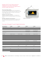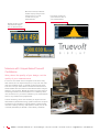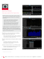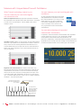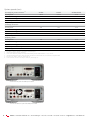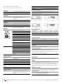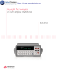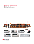
1
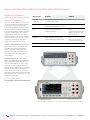
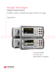
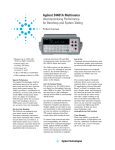
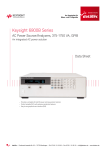
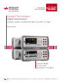
Ihr Spezialist für
Mess- und Prüfgeräte
Keysight Technologies
Digital Multimeters
34460A, 34461A, 34465A (6½ digit), 34470A (7½ digit)
Data Sheet
Truevolt DMMs
for your next
generation of insights
dataTec ▪ Ferdinand-Lassalle-Str. 52 ▪ 72770 Reutlingen ▪ Tel. 07121 / 51 50 50 ▪ Fax 07121 / 51 50 10 ▪ [email protected] ▪ www.datatec.de
02 | Keysight | Digital Multimeters: 34460/61/65/70A - Data Sheet
Keysight’s NEW Truevolt Digital Multimeters
(DMMs) offer a full range of measurement
capabilities and price points with higher levels of
accuracy, speed, and resolution.
Get more insight quickly
Truevolt DMM's graphical capabilities such as trend and histogram charts offer more insights quickly. Both models also provide
a data logging mode for easier trend analysis and a digitizing
mode for capturing transients.
Measure low-power devices
The ability to measure very low current, 1 µA range with pA
resolution, allows you to make measurements on very low power
devices.
Maintain calibrated measurements
Auto calibration allows you to compensate for temperature drift
so you can maintain measurement accuracy throughout your
workday.
The bright, 4.3” high-resolution monitor is a prominent feature of
Keysight’s Truevolt DMM family.
Overview of Keysight Truevolt Digital Multimeters
Key specifications
34460A
34461A
34465A
34470A
Digits of resolution
6½
6½
6½
7½
Basic DCV accuracy
75 ppm
35 ppm
30 ppm
16 ppm
Max reading rate
300 rdgs/s
1,000 rdgs/s
5,000 rdgs/s std
50,000 rdgs/s opt
5,000 rdgs/s std
50,000 rdgs/s opt
Memory
1,000 rdgs
10,000 rdgs
50,000 rdgs std
2 million rdgs opt
50,000 rdgs std
2 million rdgs opt
DCV, ACV
100 mV to 1,000 V
100 mV to 1,000 V
100 mV to 1,000 V
100 mV to 1,000 V
DCI
100 μA to 3 A
100 μA to 10 A
1 μA to 10 A
1 μA to 10 A
ACI
100 μA to 3 A
100 μA to 10 A
100 μA to 10 A
100 μA to 10 A
2- and 4-wire resistance
100 Ω to 100 MΩ
100 Ω to 100 MΩ
100 Ω to 1,000 MΩ
100 Ω to 1,000 MΩ
Continuity, diode
Y, 5 V
Y, 5 V
Y, 5 V
Y, 5 V
Frequency, period
3 Hz to 300 kHz
3 Hz to 300 kHz
3 Hz to 300 kHz
3 Hz to 300 kHz
Temperature
RTD/PT100, thermistor
RTD/PT100, thermistor
RTD/PT100, thermistor,
thermocouples
RTD/PT100, thermistor,
thermocouples
Capacitance
1.0 nF to 100.0 µF
1.0 nF to 100.0 µF
1.0 nF to 100.0 μF
1.0 nF to 100.0 μF
Dual line display
Yes
Yes
Yes
Yes
Display
Color, graphical
Color, graphical
Color, graphical
Color, graphical
Statistical graphics
Histogram, bar chart
Histogram, bar chart, trend
chart
Histogram, bar chart, trend
chart
Histogram, bar chart, trend
chart
Rear input terminals
No
Yes
Yes
Yes
USB
Yes
Yes
Yes
Yes
LAN/LXI Core
Optional
Yes
Yes
Yes
GPIB
Optional
Optional
Optional
Optional
Measurements
IO interface
2
dataTec ▪ Ferdinand-Lassalle-Str. 52 ▪ 72770 Reutlingen ▪ Tel. 07121 / 51 50 50 ▪ Fax 07121 / 51 50 10 ▪ [email protected] ▪ www.datatec.de
03 | Keysight | Digital Multimeters: 34460/61/65/70A - Data Sheet
Bar meter mode provides the
number display along with an
analog meter to provide
a visual view of your
measurements.
Histogram mode gives
you a statistical view of
your measurements.
Number mode provides
the traditional “digits”
view of measurements.
Measure with Unquestioned Truevolt
Confidence
Worry about the quality of your design, not the
quality of your measurements
In a rack or on a bench real-world signals are never flat. They
have some level of AC signal riding on top from power line noise,
other environmental noise, or injected current from the meter
itself. How well your meter deals with these extraneous factors
and eliminates them from the true measurement makes a big difference to your accuracy. Behind the scenes, Keysight’s Truevolt
technology accounts for measurement errors created by these
real-world factors so you can be confident in your measurements
and it is only available on Keysight DMMs.
Truevolt technology starts with an analog-to-digital converter
that enables a patented metrology-grade architecture. Using this
architecture, Keysight delivers a good balance of measurement
resolution, linearity, accuracy, and speed at a value price, all derived and guaranteed per ISO/IEC 17025 industry standards.
3
dataTec ▪ Ferdinand-Lassalle-Str. 52 ▪ 72770 Reutlingen ▪ Tel. 07121 / 51 50 50 ▪ Fax 07121 / 51 50 10 ▪ [email protected] ▪ www.datatec.de
04 | Keysight | Digital Multimeters: 34460/61/65/70A - Data Sheet
BenchVue Software
Data capture simplied. Click. Capture. Done.
BenchVue software for the PC makes it simple to connect,
control, capture and view Keysight's DMMs simultaneously
with other Keysight bench instruments with no additional
programming.
–
–
–
–
–
–
–
Figure 1. See your measurements across instruments in one place to quickly
correlate measurement activities and obtain actionable insights.
Visualize multiple measurements simultaneously
Easily log data, screen shots and system state
Rapidly prototype custom test sequences
Recall past state of your bench to replicate results
Export measurement data in desired format fast
Quickly access manuals, drivers, FAQs and videos
Monitor and control bench from mobile devices
The Digital Multimeter App within BenchVue enables control
of digital multimeters to visualize measurements, perform
data logging 1 and annotate captured data (included in model
BV0000A). Upgrading to the Pro version (model #BV0001A)
provides histograms, digitizer capability and unrestricted data
logging with limit checking and alerts.
Benefit from a new perspective by visualizing
multiple DMM’s at the same time
– Display single measurements, charts, tables, or histograms
from a single instrument or multiple DMMs simultaneously to
correlate trends you might otherwise miss.
Record measurements and export results in a few
clicks
– Log and export data quickly to popular tools such
as Microsoft Excel, Microsoft Word and MATLAB for
documentation or further analysis.
Access and control tests on your DMM remotely
– With the companion BenchVue Mobile app, monitor and
respond to long-running tests from anywhere.
Download BenchVue software at no cost today
www.keysight.com/find/benchvue
Figure 2. BenchVue enables control of your DMM to data log and visualize
measurements in a wide array of display options.
1. One hour limit in no-cost version.
4
dataTec ▪ Ferdinand-Lassalle-Str. 52 ▪ 72770 Reutlingen ▪ Tel. 07121 / 51 50 50 ▪ Fax 07121 / 51 50 10 ▪ [email protected] ▪ www.datatec.de
05 | Keysight | Digital Multimeters: 34460/61/65/70A - Data Sheet
Measure with Unquestioned Truevolt Confidence
What Truevolt technology means to you:
You can measure your real-world signals,
not instrument error
Noise and injected current: Keysight Truevolt DMMs contribute
less than 30% of the injected current than alternatives. Compared
to some lower cost alternatives, Truevolt DMMs offer almost
100% less noise.
800
700
You can measure your real-world signals with
confidence
All Truevolt DMM specifications are tested
and guaranteed for compliance with ISO/
IEC 17025 standards so you can prove the
effectiveness of your lab or production
line’s quality management system. Many
lower-cost DMMs in this class do not
carry a guarantee of their measurement
specifications.
600
You can take advantage of expanded
measurement functionality
nA
500
400
300
200
100
0
Truevolt
Brand A
Brand B
Brand C
Input bias current: Ideally, no current flows into the measurement
terminals of your DMM. In real measurement situations, there are
always input currents creating additional measurement errors.
Truevolt DMMs take care of input bias current. Some alternative
DMMs offer 20% to infinitely poorer performance (some are too
noisy to measure).
Compared to the 34401A DMM, Truevolt DMMs offer expanded
current ranges from 100 µA to 10 A. We have also added
a temperature measurement function (RTD/PT100, 5 kΩ
thermistor). Additionally, diode measurement capability has been
expanded to allow a larger full-scale voltage to be measured (5 V)
to enable the measurement of more diode types such as LEDs.
60
50
Input
bias
current
too
noisy
to
measure
pA
40
30
20
10
0
Truevolt
Brand A
Brand B
Brand C
Digital AC rms measurements: For meters in this class, only
Keysight uses digital direct sampling techniques to make AC rms
measurements. This results in a true rms calculation technique
that avoids the slower response of analog RMS converters used
in all other vendor’s 6½ digit DMMs. This allows for crest factors
up to 10 without additional error terms. This is a unique, patented
technique – only used by Keysight.
Crest factor: the ratio of the
peak value to the RMS value
of a waveform
Peak value
RMS value
AC measurement
accuracy is degraded
when signals have
energy contained in
higher frequencies
than a typical sine
wave.
5
dataTec ▪ Ferdinand-Lassalle-Str. 52 ▪ 72770 Reutlingen ▪ Tel. 07121 / 51 50 50 ▪ Fax 07121 / 51 50 10 ▪ [email protected] ▪ www.datatec.de
06 | Keysight | Digital Multimeters: 34460/61/65/70A - Data Sheet
Move to The Next-Generation 34401A DMM with 100% Assurance
Migrate with confidence:
Everything you depend on with
the 34401A and more
Like most 34401A DMM owners, you rely
on your DMM and you trust the answers
it gives you. Now, with the Keysight
Truevolt 34461A DMM, you can get all of
the advantages of the 34401A and more.
Now you can get faster answers and have
even more confidence in your results.
The best news of all? You can migrate
from the 34401A to the 34461A without a
hassle. No need to rewrite your software
programs or spend hours learning a
brand-new, complicated interface.
Use your existing programs: The 34461A
DMM is the industry’s only 100% dropin, SCPI-compatible replacement for
the 34401A DMM. Other DMMs may
claim 34401A SCPI compatibility, but
only a subset of SCPI commands are
implemented.
Migration Q&A
QUESTION
ANSWER
Program
compatibility
Will my existing programs still work
if I switch to the 34461A?
YES
Measurements
Will I have the same performance so it
doesn’t affect the results on my line?
YES
Cost
Will it cost the same to buy, use,
maintain, and repair?
YES
(and potentially less since the
DMMs now include a 3-year
standard warranty)
Reliability
My 34401A never breaks. Are the
Truevolt DMMs going to be as good?
YES
That’s why we can offer
a 3-year standard warranty
Use
Will we be able to use it easily? Quickly?
YES
No long learning curve: The Truevolt
DMMs were designed by the same team
that created the 34401A. The team kept
34401A measurements, reliability and
familiarity in mind as they created the
Truevolt family of DMMs. So you can use it
without spending hours learning how.
The 34461A represents everything you
have known and trusted with your Keysight
DMM measurements for decades – it just
keeps getting stronger.
For more information visit:
www.keysight.com/find/34401Amigration
34461A: The industry’s only 100% drop-in, SCPI-compatible replacement for the 34401A DMM
6
dataTec ▪ Ferdinand-Lassalle-Str. 52 ▪ 72770 Reutlingen ▪ Tel. 07121 / 51 50 50 ▪ Fax 07121 / 51 50 10 ▪ [email protected] ▪ www.datatec.de
07 | Keysight | Digital Multimeters: 34460/61/65/70A - Data Sheet
Specifications 34460A
34460A accuracy specifications: ± (% of reading + % of range) 1
These specification are compliant to ISO/IEC 17025 for K = 2
Range 2 /frequency
24 hours 3
TCAL ± 1 °C
90 days
TCAL ± 5 °C
1 year
TCAL ± 5 °C
2 years
TCAL ± 5 °C
Temperature
coefficient/°C 4
0.0040 + 0.0060
0.0070 + 0.0065
0.0090 + 0.0065
0.0115 + 0.0065
0.0005 + 0.0005
DC voltage
100 mV
1V
0.0030 + 0.0009
0.0060 + 0.0010
0.0080 + 0.0010
0.0105 + 0.0010
0.0005 + 0.0001
10 V
0.0025 + 0.0004
0.0050 + 0.0005
0.0075 + 0.0005
0.0100 + 0.0005
0.0005 + 0.0001
100 V
0.0030 + 0.0006
0.0065 + 0.0006
0.0085 + 0.0006
0.0110 + 0.0006
0.0005 + 0.0001
0.0030 + 0.0006
0.0065 + 0.0010
0.0085 + 0.0010
0.0110 + 0.0010
0.0005 + 0.0001
1000 V
True RMS AC voltage
2, 5, 6
100 mV, 1 V, 10 V, 100 V, and 750 V ranges
3 – 5 Hz
1.00 + 0.02
1.00 + 0.03
1.00 + 0.03
1.00 + 0.03
0.100 + 0.003
5 – 10 Hz
0.38 + 0.02
0.38 + 0.03
0.38 + 0.03
0.38 + 0.03
0.035 + 0.003
10 Hz – 20 kHz
0.07 + 0.02
0.08 + 0.03
0.09 + 0.03
0.10 + 0.03
0.005 + 0.003
20 – 50 kHz
0.13 + 0.04
0.14 + 0.05
0.15 + 0.05
0.16 + 0.05
0.011 + 0.005
50 – 100 kHz
0.58 + 0.08
0.63 + 0.08
0.63 + 0.08
0.63 + 0.08
0.060 + 0.008
100 – 300 kHz
4.00 + 0.50
4.00 + 0.50
4.00 + 0.50
4.00 + 0.50
0.200 + 0.020
Resistance
Test current
7
100 Ω
1 mA
0.0040 + 0.0060
0.011 + 0.007
0.014 + 0.007
0.017 + 0.007
0.0006 + 0.0005
1 kΩ
1 mA
0.0030 + 0.0008
0.011 + 0.001
0.014 + 0.001
0.017 + 0.001
0.0006 + 0.0001
10 kΩ
100 µA
0.0030 + 0.0005
0.011 + 0.001
0.014 + 0.001
0.017 + 0.001
0.0006 + 0.0001
100 kΩ
10 µA
0.0030 + 0.0005
0.011 + 0.001
0.014 + 0.001
0.017 + 0.001
0.0006 + 0.0001
1 MΩ
5 µA
0.0030 + 0.0010
0.011 + 0.001
0.014 + 0.001
0.017 + 0.001
0.0010 + 0.0002
10 MΩ
500 nA
0.015 + 0.001
0.020 + 0.001
0.040 + 0.001
0.060 + 0.001
0.0030 + 0.0004
100 MΩ
500 nA || 10 MΩ
0.300 + 0.010
0.800 + 0.010
0.800 + 0.010
0.800 + 0.010
0.1500 + 0.0002
DC current
Burden voltage
100 µA
<0.011 V
0.010 + 0.020
0.040 + 0.025
0.050 + 0.025
0.060 + 0.025
0.0020 + 0.0030
1 mA
<0.11 V
0.007 + 0.006
0.030 + 0.006
0.050 + 0.006
0.060 + 0.006
0.0020 + 0.0005
10 mA
<0.05 V
0.007 + 0.020
0.030 + 0.020
0.050 + 0.020
0.060 + 0.020
0.0020 + 0.0020
100 mA
<0.5 V
0.010 + 0.004
0.030 + 0.005
0.050 + 0.005
0.060 + 0.005
0.0020 + 0.0005
1A
<0.7 V
0.050 + 0.006
0.080 + 0.010
0.100 + 0.010
0.120 + 0.010
0.0050 + 0.0010
<2.0 V
0.180 + 0.020
0.200 + 0.020
0.200 + 0.020
0.230 + 0.020
0.0050 + 0.0020
1.0000 nF
0.50 + 0.50
0.50 + 0.50
0.50 + 0.50
0.50 + 0.50
0.05 + 0.05
10.000 nF
0.40 + 0.10
0.40 + 0.10
0.40 + 0.10
0.40 + 0.10
0.05 + 0.01
3A
Capacitance
7
15
100.00 nF
0.40 + 0.10
0.40 + 0.10
0.40 + 0.10
0.40 + 0.10
0.05 + 0.01
1.0000 µF
0.40 + 0.10
0.40 + 0.10
0.40 + 0.10
0.40 + 0.10
0.05 + 0.01
10.000 µF
0.40 + 0.10
0.40 + 0.10
0.40 + 0.10
0.40 + 0.10
0.05 + 0.01
100.00 µF
0.40 + 0.10
0.40 + 0.10
0.40 + 0.10
0.40 + 0.10
0.05 + 0.01
dataTec ▪ Ferdinand-Lassalle-Str. 52 ▪ 72770 Reutlingen ▪ Tel. 07121 / 51 50 50 ▪ Fax 07121 / 51 50 10 ▪ [email protected] ▪ www.datatec.de
08 | Keysight | Digital Multimeters: 34460/61/65/70A - Data Sheet
Specifications 34460A
24 hours 3
TCAL ± 1 °C
90 days
TCAL ± 5 °C
1 year
TCAL ± 5 °C
2 years
TCAL ± 5 °C
Temperature
coefficient/°C 4
0.10 + 0.04
0.10 + 0.04
0.10 + 0.04
0.10 + 0.04
0.015 + 0.006
0.10 + 0.04
0.10 + 0.04
0.10 + 0.04
0.10 + 0.04
0.030 + 0.006
3 Hz – 5 kHz
0.10 + 0.04
0.10 + 0.04
0.10 + 0.04
0.10 + 0.04
0.015 + 0.006
5 – 10 kHz (typ)
0.10 + 0.04
0.10 + 0.04
0.10 + 0.04
0.10 + 0.04
0.030 + 0.006
3 Hz – 5 kHz
0.23 + 0.04
0.23 + 0.04
0.23 + 0.04
0.23 + 0.04
0.015 + 0.006
5 – 10 kHz (typ)
0.23 + 0.04
0.23 + 0.04
0.23 + 0.04
0.23 + 0.04
0.030 + 0.006
0.002 + 0.030
0.008 + 0.030
0.010 + 0.030
0.012 + 0.030
0.0010 + 0.0020
0.002 + 0.030
0.008 + 0.030
0.010 + 0.030
0.012 + 0.030
0.0010 + 0.0020
Range 2 /frequency
True RMS AC current 2, 6, 8
Burden voltage
100 µA, 1 mA, 10 mA, and
100 mA ranges
< 0.011, < 0.11, < 0.05, < 0.5 V
3 Hz – 5 kHz
5 – 10 kHz (typ)
1 A range
< 0.7 V
3 A range
< 2.0 V
Continuity
1 kΩ
Diode test 9
5V
DC ratio (typ)
(normalized input accuracy) + (normalized reference accuracy)
Temperature
10
PT100 (DIN/ IEC 751)
Probe accuracy + 0.05 °C
5 kΩ thermistor
Probe accuracy + 0.1 °C
Frequency: specification ± (% of reading) 11, 12
100 mV, 1 V, 10 V, 100 V, and 750 V ranges 13
3 – 10 Hz
0.100
0.100
0.100
0.100
0.0002
10 – 100 Hz
0.030
0.030
0.030
0.035
0.0002
100 Hz – 1 kHz
0.030
0.010
0.012
0.017
0.0002
1 – 300 kHz
0.002
0.008
0.012
0.017
0.0002
0.001
0.008
0.012
0.017
0.0002
Frequency
1 second
0.1 second
0.01 second
3 – 40 Hz
0
0.200
0.200
40 – 100 Hz
0
0.060
0.200
100 Hz – 1 kHz
0
0.020
0.200
1 – 300 kHz
0
0.004
0.030
0
0
0
Square wave
14
Additional gate time errors ± ( % of reading )
Square wave
1.
2.
3.
4.
5.
6.
7.
8.
9.
10.
11.
12.
13.
14.
15.
8
14
12, 10
For DC: Specifications are for 60-minute warm-up, aperture of 10 or 100 NPLC, and auto zero on. For AC: Specifications are for 60-minute warm-up, slow AC filter, sine wave.
20% overrange on all ranges, except 1,000 V DCV, 750 ACV, 3 A AC, and diode test.
Relative to calibration standards.
Add this for each °C outside TCAL ± 5 °C.
Specifications are for sine wave input > 0.3% of range and > 1 mVrms. 750 ACV range limited to 8 x 10⁷ Volt–Hz.
Low-frequency performance: three filter settings are available: 3 Hz, 20 Hz, 200 Hz. Frequencies greater than these filter settings are specified with no additional errors.
Specifications are for 4–wire ohms function or 2–wire ohms using math null for offset. Without math null, add 0.2 Ω additional error in 2-wire ohms function.
Specifications are for sinewave input > 1% of range and > 10 µA AC.
Specifications are for the voltage measured at the input terminals. The 1 mA test current is typical. Variation in the current source will create some variation in the voltage
drop across a diode junction.
Actual measurement range and probe errors will be limited by the selected probe. Probe accuracy adder includes all measurement and ITS-90 temperature conversion errors
PT100 Ro settable to 100 Ω ± 5 Ω to remove the initial probe error.
Specifications are for 60-minute warm-up and sine wave input unless stated otherwise. Specifications are for 1-second gate time (7 digits).
Applies to sine and square inputs ≥ 100 mV. For 10 mV to < 100 mV inputs, multiply % of reading error x10.
Amplitude 10% – 120% of range and less than 750 ACV.
Square wave input specified for 10 – 300 kHz.
Specifications are for using Math Null zeroing. High dissapation factor capacitors may show different results than a single frequency measurement. Film capacitors usually
have lower dissapation factors than other dielectrics.
dataTec ▪ Ferdinand-Lassalle-Str. 52 ▪ 72770 Reutlingen ▪ Tel. 07121 / 51 50 50 ▪ Fax 07121 / 51 50 10 ▪ [email protected] ▪ www.datatec.de
09 | Keysight | Digital Multimeters: 34460/61/65/70A - Data Sheet
Specifications 34461A
34461A accuracy specifications: ± (% of reading + % of range) 1
These specification are compliant to ISO/IEC 17025 for K = 2
Range 2 /frequency
24 hours 3
TCAL ± 1 °C
90 days
TCAL ± 5 °C
1 year
TCAL ± 5 °C
2 years
TCAL ± 5 °C
Temperature
coefficient/°C 4
DC voltage
100 mV
0.0030 + 0.0030
0.0040 + 0.0035
0.0050 + 0.0035
0.0065 + 0.0035
0.0005 + 0.0005
1V
0.0020 + 0.0006
0.0030 + 0.0007
0.0040 + 0.0007
0.0055 + 0.0007
0.0005 + 0.0001
10 V
0.0015 + 0.0004
0.0020 + 0.0005
0.0035 + 0.0005
0.0050 + 0.0005
0.0005 + 0.0001
100 V
0.0020 + 0.0006
0.0035 + 0.0006
0.0045 + 0.0006
0.0060 + 0.0006
0.0005 + 0.0001
1000 V
0.0020 + 0.0006
0.0035 + 0.0010
0.0045 + 0.0010
0.0060 + 0.0010
0.0005 + 0.0001
1.00 + 0.02
1.00 + 0.03
1.00 + 0.03
1.00 + 0.03
0.100 + 0.003
True RMS AC voltage 2, 5, 6
100 mV, 1 V, 10 V, 100 V, and 750 V ranges
3 – 5 Hz
5 – 10 Hz
0.35 + 0.02
0.35 + 0.03
0.35 + 0.03
0.35 + 0.03
0.035 + 0.003
10 Hz – 20 kHz
0.04 + 0.02
0.05 + 0.03
0.06 + 0.03
0.07 + 0.03
0.005 + 0.003
20 – 50 kHz
0.10 + 0.04
0.11 + 0.05
0.12 + 0.05
0.13 + 0.05
0.011 + 0.005
50 – 100 kHz
0.55 + 0.08
0.60 + 0.08
0.60 + 0.08
0.60 + 0.08
0.060 + 0.008
4.00 + 0.50
4.00 + 0.50
4.00 + 0.50
4.00 + 0.50
0.200 + 0.020
0.0030 + 0.0030
0.008 + 0.004
0.010 + 0.004
0.012 + 0.004
0.0006 + 0.0005
100 – 300 kHz
Resistance
Test current
7
100 Ω
1 mA
1 kΩ
1 mA
0.0020 + 0.0005
0.008 + 0.001
0.010 + 0.001
0.012 + 0.001
0.0006 + 0.0001
10 kΩ
100 µA
0.0020 + 0.0005
0.008 + 0.001
0.010 + 0.001
0.012 + 0.001
0.0006 + 0.0001
100 kΩ
10 µA
0.0020 + 0.0005
0.008 + 0.001
0.010 + 0.001
0.012 + 0.001
0.0006 + 0.0001
1 MΩ
5 µA
0.002 + 0.001
0.008 + 0.001
0.010 + 0.001
0.012 + 0.001
0.0010 + 0.0002
10 MΩ
500 nA
0.015 + 0.001
0.020 + 0.001
0.040 + 0.001
0.060 + 0.001
0.0030 + 0.0004
100 MΩ
500 nA || 10 MΩ
0.300 + 0.010
0.800 + 0.010
0.800 + 0.010
0.800 + 0.010
0.1500 + 0.0002
DC current
Burden voltage
100 µA
<0.011 V
0.010 + 0.020
0.040 + 0.025
0.050 + 0.025
0.060 + 0.025
0.0020 + 0.0030
1 mA
<0.11 V
0.007 + 0.006
0.030 + 0.006
0.050 + 0.006
0.060 + 0.006
0.0020 + 0.0005
10 mA
<0.05 V
0.007 + 0.020
0.030 + 0.020
0.050 + 0.020
0.060 + 0.020
0.0020 + 0.0020
100 mA
<0.5 V
0.010 + 0.004
0.030 + 0.005
0.050 + 0.005
0.060 + 0.005
0.0020 + 0.0005
1A
<0.7 V
0.050 + 0.006
0.080 + 0.010
0.100 + 0.010
0.120 + 0.010
0.0050 + 0.0010
3A
<2.0 V
0.180 + 0.020
0.200 + 0.020
0.200 + 0.020
0.230 + 0.020
0.0050 + 0.0020
10 A 8
<0.5 V
0.050 + 0.010
0.120 + 0.010
0.120 + 0.010
0.150 + 0.010
0.0050 + 0.0010
Capacitance
9
15
1.0000 nF
0.50 + 0.50
0.50 + 0.50
0.50 + 0.50
0.50 + 0.50
0.05 + 0.05
10.000 nF
0.40 + 0.10
0.40 + 0.10
0.40 + 0.10
0.40 + 0.10
0.05 + 0.01
100.00 nF
0.40 + 0.10
0.40 + 0.10
0.40 + 0.10
0.40 + 0.10
0.05 + 0.01
1.0000 µF
0.40 + 0.10
0.40 + 0.10
0.40 + 0.10
0.40 + 0.10
0.05 + 0.01
10.000 µF
0.40 + 0.10
0.40 + 0.10
0.40 + 0.10
0.40 + 0.10
0.05 + 0.01
100.00 µF
0.40 + 0.10
0.40 + 0.10
0.40 + 0.10
0.40 + 0.10
0.05 + 0.01
dataTec ▪ Ferdinand-Lassalle-Str. 52 ▪ 72770 Reutlingen ▪ Tel. 07121 / 51 50 50 ▪ Fax 07121 / 51 50 10 ▪ [email protected] ▪ www.datatec.de
10 | Keysight | Digital Multimeters: 34460/61/65/70A - Data Sheet
Specifications 34461A
Range 2 /frequency
True RMS AC current 2, 6, 9
100 µA, 1 mA, 10 mA, and
100 mA ranges
3 Hz – 5 kHz
5 – 10 kHz (typ)
1 A range
3 Hz – 5 kHz
5 – 10 kHz (typ)
3 A range
3 Hz – 5 kHz
5 – 10 kHz (typ)
10 A range 8
3 Hz – 5 kHz
5 – 10 kHz (typ)
Continuity
1 kΩ
24 hours 3
TCAL ± 1 °C
90 days
TCAL ± 5 °C
1 year
TCAL ± 5 °C
2 years
TCAL ± 5 °C
Temperature
coefficient/°C 4
0.10 + 0.04
0.10 + 0.04
0.10 + 0.04
0.10 + 0.04
0.10 + 0.04
0.10 + 0.04
0.10 + 0.04
0.10 + 0.04
0.015 + 0.006
0.030 + 0.006
0.10 + 0.04
0.10 + 0.04
0.10 + 0.04
0.10 + 0.04
0.10 + 0.04
0.10 + 0.04
0.10 + 0.04
0.10 + 0.04
0.015 + 0.006
0.030 + 0.006
0.23 + 0.04
0.23 + 0.04
0.23 + 0.04
0.23 + 0.04
0.23 + 0.04
0.23 + 0.04
0.23 + 0.04
0.23 + 0.04
0.015 + 0.006
0.030 + 0.006
0.15 + 0.04
0.15 + 0.04
0.15 + 0.04
0.15 + 0.04
0.15 + 0.04
0.15 + 0.04
0.15 + 0.04
0.15 + 0.04
0.015 + 0.006
0.030 + 0.006
0.002 + 0.030
0.008 + 0.030
0.010 + 0.030
0.012 + 0.030
0.0010 + 0.0020
0.002 + 0.030
0.008 + 0.030
0.010 + 0.030
0.012 + 0.030
0.0010 + 0.0020
Burden voltage
< 0.011, < 0.11, < 0.05, < 0.5 V
< 0.7 V
< 2.0 V
< 0.5 V
10
Diode test
5V
DC ratio (typ)
(normalized input accuracy) + (normalized reference accuracy)
11
Temperature
PT100 (DIN/ IEC 751)
5 kΩ thermistor
Probe accuracy + 0.05 °C
Probe accuracy + 0.1 °C
Frequency: specification ± (% of reading) 12, 13
100 mV, 1 V, 10 V, 100 V, and 750 V ranges 14
3 – 10 Hz
10 – 100 Hz
100 Hz – 1 kHz
1 – 300 kHz
Square wave 15
0.100
0.030
0.003
0.002
0.001
0.100
0.030
0.008
0.006
0.006
0.100
0.030
0.010
0.010
0.010
Additional gate time errors ± (% of reading) 13
Frequency
3 – 40 Hz
1 second
0
0.1 second
0.200
0.01 second
0.200
40 – 100 Hz
100 Hz – 1 kHz
1 – 300 kHz
Square wave 15
0
0
0
0
0.060
0.020
0.004
0
0.200
0.200
0.030
0
1.
2.
3.
4.
5.
6.
7.
8.
9.
10.
11.
12.
13.
14.
15.
10
0.100
0.030
0.010
0.010
0.010
0.100
0.035
0.015
0.015
0.015
For DC: Specifications are for 60-minute warm-up, aperture of 10 or 100 NPLC, and auto zero on. For AC: Specifications are for 60-minute warm-up, slow AC filter,
sine wave.
20% over range on all ranges, except 1,000 V DCV, 750 ACV, 10 A DC, 3 A AC, 10 A AC, and diode test.
Relative to calibration standards.
Add this for each °C outside TCAL ± 5 °C.
Specifications are for sinewave input >0.3% of range and > 1 mVrms. 750 ACV range limited to 8 x 10 7 Volt–Hz.
Low-frequency performance: three filter settings are available: 3 Hz, 20 Hz, 200 Hz. Frequencies greater than these filter settings are specified with no additional
errors.
Specifications are for 4-wire ohms function or 2-wire ohms using math null for offset. Without math null, add 0.2 Ω additional error in 2-wire ohms function.
The 10 A range is only available on a separate front-panel connector. Add 2 mA base per amp or inputs > 5 A rms.
Specifications are for sinewave input > 1% of range and > 10 µA AC.
Specifications are for the voltage measured at the input terminals. The 1 mA test current is typical. Variation in the current source will create some variation in the
voltage drop across a diode junction.
Actual measurement range and probe errors will be limited by the selected probe. Probe accuracy adder includes all measurement and ITS-90 temperature
conversion errors. PT100 Ro settable to 100 Ω ± 5 Ω to remove the initial probe error.
Specifications are for 60-minute warm-up and sine wave input unless stated otherwise. Specifications are for 1-second gate time (7-digits).
Applies to sine and square inputs ≥ 100 mV. For 10 mV to < 100 mV inputs, multiply % of reading error x10.
Amplitude 10% – 120% of range and less than 750 ACV.
Square wave input specified for 10 – 300 kHz.
dataTec ▪ Ferdinand-Lassalle-Str. 52 ▪ 72770 Reutlingen ▪ Tel. 07121 / 51 50 50 ▪ Fax 07121 / 51 50 10 ▪ [email protected] ▪ www.datatec.de
11 | Keysight | Digital Multimeters: 34460/61/65/70A - Data Sheet
Specifications 34465A
34465A accuracy specifications: ± (% of reading + % of range) 1
DC voltage and resistance. Automatic calibration (ACAL) capable.
24 hours 3
TACAL ± 1 °C
90 days
TACAL ± 2 °C
1 year
TACAL ± 2 °C
2 years
TACAL ± 2 °C
Non ACAL 7
Temperature
coefficient/°C
With ACAL 8
Temperature
coefficient/°C
100 mV
0.0030 + 0.0030
0.0040 + 0.0035
0.0050 + 0.0035
0.0065 + 0.0035
0.0005 + 0.0005
0.0002 + 0.0005
1V
0.0015 + 0.0004
0.0025 + 0.0004
0.0035 + 0.0004
0.0050 + 0.0004
0.0005 + 0.0001
0.0002 + 0.0001
Range 2
DC voltage
10 V
0.0010 + 0.0003
0.0020 + 0.0004
0.0030 + 0.0004
0.0045 + 0.0004
0.0005 + 0.0001
0.0002 + 0.0001
100 V
0.0020 + 0.0006
0.0035 + 0.0006
0.0040 + 0.0006
0.0055 + 0.0006
0.0005 + 0.0001
0.0002 + 0.0001
0.0020 + 0.0006
0.0035 + 0.0006
0.0040 + 0.0006
0.0055 + 0.0006
0.0005 + 0.0001
0.0002 + 0.0001
1000 V 10
Resistance
9
100 Ω
0.0030 + 0.0030
0.0050 + 0.0040
0.0060 + 0.0040
0.0070 + 0.0040
0.0006 + 0.0005
0.0002 + 0.0005
1 KΩ
0.0020 + 0.0005
0.0030 + 0.0005
0.0040 + 0.0005
0.0050 + 0.0005
0.0006 + 0.0001
0.0002 + 0.0001
10 KΩ
0.0020 + 0.0005
0.0030 + 0.0005
0.0040 + 0.0005
0.0050 + 0.0005
0.0006 + 0.0001
0.0002 + 0.0001
100 KΩ
0.0020 + 0.0005
0.0030 + 0.0005
0.0040 + 0.0005
0.0050 + 0.0005
0.0006 + 0.0001
0.0002 + 0.0001
1 MΩ
0.0020 + 0.0005
0.0060 + 0.0005
0.0070 + 0.0005
0.0080 + 0.0005
0.0010 + 0.0002
0.0002 + 0.0002
10 MΩ
0.010 + 0.001
0.020 + 0.001
0.025 + 0.001
0.030 + 0.001
0.0030 + 0.0004
0.0030 + 0.0004
100 MΩ
0.100 + 0.001
0.200 + 0.001
0.300 + 0.001
0.400 + 0.001
0.1000 + 0.0001
0.0100 + 0.0001
1000 MΩ
2.000 + 0.001
2.000 + 0.001
3.000 + 0.001
4.000 + 0.001
1.0000 + 0.0001
0.1000 + 0.0001
24 hours 3
TCAL ± 1 °C
90 days
TCAL ± 5 °C
1 year
TCAL ± 5 °C
2 years
TCAL ± 5 °C
Temperature
coefficient/°C 6
1 µA (typ)
0.007 + 0.005
0.030 + 0.005
0.050 + 0.005
0.060 + 0.005
0.0020 + 0.0010
10 µA (typ)
0.007 + 0.002
0.030 + 0.002
0.050 + 0.002
0.060 + 0.002
0.0015 + 0.0006
100 µA (typ)
0.007 + 0.001
0.030 + 0.001
0.050 + 0.001
0.060 + 0.001
0.0015 + 0.0004
Range 2
DC current
1 mA
0.007 + 0.003
0.030 + 0.005
0.050 + 0.005
0.060 + 0.005
0.0015 + 0.0005
10 mA
0.007 + 0.020
0.030 + 0.020
0.050 + 0.020
0.060 + 0.020
0.0020 + 0.0020
100 mA
0.010 + 0.004
0.030 + 0.005
0.050 + 0.005
0.060 + 0.005
0.0020 + 0.0005
1A
0.050 + 0.006
0.070 + 0.010
0.080 + 0.010
0.100 + 0.010
0.0050 + 0.0010
3A
0.180 + 0.020
0.200 + 0.020
0.200 + 0.020
0.230 + 0.020
0.0050 + 0.0020
10 A 5
0.050 + 0.010
0.120 + 0.010
0.120 + 0.010
0.150 + 0.010
0.0050 + 0.0010
0.002 + 0.010
0.008 + 0.020
0.010 + 0.020
0.012 + 0.020
0.0010 + 0.0020
0.002 + 0.010
0.008 + 0.010
0.010 + 0.010
0.012 + 0.020
0.0010 + 0.0010
Continuity
1 KΩ
Diode test 11
5V
DC:DC ratio (typ)
12
(normalized input accuracy) + (normalized reference accuracy)
11
dataTec ▪ Ferdinand-Lassalle-Str. 52 ▪ 72770 Reutlingen ▪ Tel. 07121 / 51 50 50 ▪ Fax 07121 / 51 50 10 ▪ [email protected] ▪ www.datatec.de
12 | Keysight | Digital Multimeters: 34460/61/65/70A - Data Sheet
Specifications 34465A
Temperature
Probe accuracy + 0.05 °C
PT100 (DIN/ IEC 751) 13
5 kΩ thermistor
Probe accuracy + 0.1 °C
K,J,T,E,N thermocouples
R thermocouples
14
14
(250 - 1760 °C)
Probe accuracy + reference junction accuracy + 0.3 °C
Probe accuracy + reference junction accuracy + 0.5 °C
24 hours 3
TCAL ± 1 °C
90 days
TCAL ± 5 °C
1 year
TCAL ± 5 °C
2 years
TCAL ± 5 °C
Temperature
coefficient/°C 6
3 – 5 Hz
0.50 + 0.02
0.50 + 0.02
0.50 + 0.02
0.50 + 0.02
0.010 + 0.003
5 – 10 Hz
0.10 + 0.02
0.10 + 0.02
0.10 + 0.02
0.11 + 0.02
0.008 + 0.003
10 Hz – 20 kHz
0.02 + 0.02
0.04 + 0.02
0.05 + 0.02
0.06 + 0.02
0.007 + 0.003
True RMS AC voltage
15, 16
100 mV, 1 V, 10 V, 100 V, and 750 V ranges
20 – 50 kHz
0.05 + 0.03
0.06 + 0.03
0.07 + 0.03
0.08+ 0.03
0.010 + 0.005
50 – 100 kHz
0.15 + 0.05
0.15 + 0.05
0.15 + 0.05
0.15 + 0.05
0.060 + 0.008
1.00 + 0.1
1.00 + 0.1
1.00 + 0.1
1.00 + 0.1
0.200 + 0.020
5 kHz – 10 kHz (typ)
3 A range
3 Hz – 5 kHz
5 kHz – 10 kHz (typ)
0.07 + 0.04
0.10 + 0.04
0.09 + 0.04
0.10 + 0.04
0.10 + 0.04
0.10 + 0.04
0.10 + 0.04
0.10 + 0.04
0.015 + 0.006
0.030 + 0.006
0.23 + 0.04
0.23 + 0.04
0.23 + 0.04
0.23 + 0.04
0.23 + 0.04
0.23 + 0.04
0.23 + 0.04
0.23 + 0.04
0.015 + 0.006
0.030 + 0.006
10 A range 5
3 Hz – 5 kHz
5 kHz – 10 kHz (typ)
0.10 + 0.04
0.15 + 0.04
0.15 + 0.04
0.15 + 0.04
0.15 + 0.04
0.15 + 0.04
0.15 + 0.04
0.15 + 0.04
0.015 + 0.006
0.030 + 0.006
0.50 + 0.50
0.40 + 0.10
0.40 + 0.10
0.40 + 0.10
0.40 + 0.10
0.40 + 0.10
0.50 + 0.50
0.40 + 0.10
0.40 + 0.10
0.40 + 0.10
0.40 + 0.10
0.40 + 0.10
0.50 + 0.50
0.40 + 0.10
0.40 + 0.10
0.40 + 0.10
0.40 + 0.10
0.40 + 0.10
0.50 + 0.50
0.40 + 0.10
0.40 + 0.10
0.40 + 0.10
0.40 + 0.10
0.40 + 0.10
0.05 + 0.05
0.05 + 0.01
0.05 + 0.01
0.05 + 0.01
0.05 + 0.01
0.05 + 0.01
0.070
0.030
0.003
0.002
0.001
0.070
0.030
0.006
0.005
0.004
0.070
0.030
0.007
0.007
0.006
0.070
0.030
0.010
0.009
0.008
0.0002
0.0002
0.0002
0.0002
0.0002
Aperture (resolution/range)
1 second
(0.1 ppm)
0.1 second
(1 ppm)
0.01 second
(10 ppm)
0.001 second
(100 ppm)
3 – 40 Hz
40 – 100 Hz
100 Hz – 1 kHz
1 – 300 kHz
0
0
0
0
0
0.100
0.030
0.020
0.004
0.000
0.160
0.160
0.200
0.030
0.000
0.160
0.160
0.200
0.240
0.003
100 – 300 kHz
True RMS AC current
16, 17
100 µA, 1 mA, 10 mA, 100 mA, 1 A ranges
3 Hz – 5 kHz
Capacitance 21
1.0000 nF
10.000 nF
100.00 nF
1.0000 µF
10.000 µF
100.00 µF
Frequency 18, 20
100 mV, 1 V, 10 V, 100 V, and 750 V ranges 20
3 – 10 Hz
10 – 100 Hz
100 Hz – 1 kHz
1 – 300 kHz
Square wave 19
Additional frequency errors ± ( % of reading ) 18
Square wave 19
12
dataTec ▪ Ferdinand-Lassalle-Str. 52 ▪ 72770 Reutlingen ▪ Tel. 07121 / 51 50 50 ▪ Fax 07121 / 51 50 10 ▪ [email protected] ▪ www.datatec.de
13 | Keysight | Digital Multimeters: 34460/61/65/70A - Data Sheet
Specifications 34465A
DC and AC current burden voltage at full scale
DC current range
Burden voltage
1 µA
10 µA
100 µA
1 mA
10 mA
100 mA
1A
< 0.0011 V
< 0.011 V
< 0.11 V
< 0.11 V
< 0.027 V
< 0.27 V
3A
< 2.0 V/0.15 V 22
< 0.5 V
< 0.7 V/0.05 V 22
10 A
Digitizing
Typical performance for these conditions: Sample rate: 50 kHz (Aperture = 20 µS); Sine wave input: Vpeak = Full scale of range; Input frequency: 1 kHz/10 kHz
Function: range
Spur-free range
SFDR
THD + noise
SNDR
BW (-3 db)
DCV: 0.1, 1 V
DCV: 10 V
DCV: 100, 1000 V
DCI: 0.1, 1 mA
DCI: 10, 100 mA
DCI: 1-10 A
79/60
86/59
64/42
78/62
78/62
65/49
75/57
82/58
60/42
75/60
67/60
63/48
15 kHz
15 kHz
15 kHz
10 kHz
10 kHz
10 kHz
1.
2.
3.
5.
6.
7.
8.
9.
10.
11.
12.
13.
14.
15.
16.
17.
18.
19.
20.
21.
22.
13
Specifications are for 60-minute warm-up, integration setting of 10 or 100 NPLC, auto-zero on, AC slow filter. ACAL run within the last 2 days.
20% over range on all ranges, except 1000 DCV, 750 ACV, 10 DCA, 3 DCA, 10 ACA, 3 ACA, and diode test have 0%.
Relative to calibration standards.
The 10 A range is only available on a separate front panel connector. Add 2 mA per amp for inputs greater than 5 Arms.
Add this for each °C outside TCAL ± 5 °C.
Add this for each °C outside the last ACAL ± 2 °C.
Add this for each °C outside TCAL ± 2 °C.
Specifications are for 4-wire ohms function or 2-wire ohms using math null for offset. Without math null, add 0.2 Ω additional error in 2-wire ohms function.
The 100 M and 1 G ohm ranges are 2-wire only. See the manual for low power ohms specification and measurement currents
For each additional volt over ± 500 V add 0.02 mV of error.
Specifications are for the voltage measured at the input terminals. The 1 mA test current is typical. Variation in the current source will create some variation
in the voltage drop across a diode junction.
See user manual for details.
Actual measurement range and probe errors will be limited by the selected probe. Probe accuracy adder includes all measurement and ITS-90 temperature
conversion errors. PT100 Ro settable to 100 Ω ± 5 Ω to remove the initial probe error.
The internal reference junction uses the U1180A or equivalent adapter. This has a typical performance of ± 1.0 °C.
This internal reference junction can be adjusted for better accuracy. An external reference junction can also be used.
Specifications are for sinewave input > 0.3% of range and > 1 mVrms. 750 ACV range limited to 8 x 10 7 Volt–Hz.
For each additional volt over 300 Vrms add 1 mVrms of error.
Low-frequency performance: three filter settings are available: 3 Hz, 20 Hz, 200 Hz. Frequencies greater than these filter settings are specified with no
additional errors.
Specifications are for sinewave input > 1% of range and > 10 µArms.
Specifications are for sine wave input unless stated otherwise.
Square wave input specified for 10 – 300 kHz for 1 second aperature. For shorter aperatures the minimun frequency requires > 2 cycles.
Input > 100 mV. For 10 mV to 100 mV inputs, multiply % of reading error x10. Amplitude 10 – 120% of range except 14 – 100% for the 750 ACV range.
Specifications are for 1-second gate time (7-digits).
Specifications are for using Math Null zeroing. High dissapation factor capacitors may show different results than a single frequency measurement. Film
capacitors usually have lower dissapation factors than other dielectrics.
The second burden voltage can be obtained by using the 10 A input range.
dataTec ▪ Ferdinand-Lassalle-Str. 52 ▪ 72770 Reutlingen ▪ Tel. 07121 / 51 50 50 ▪ Fax 07121 / 51 50 10 ▪ [email protected] ▪ www.datatec.de
14 | Keysight | Digital Multimeters: 34460/61/65/70A - Data Sheet
Specifications 34470A
34470A accuracy specifications: ± (% of reading + % of range) 1
DC voltage and resistance. Automatic calibration (ACAL) capable.
Range 2
24 hours 3
TACAL ± 1 °C
90 days
TACAL ± 5 °C
1 year
TACAL ± 5 °C
2 years
TACAL ± 5 °C
Non ACAL 11
Temperature
coefficient/°C
With ACAL 12
Temperature
coefficient/°C
DC voltage
100 mV
0.0030 + 0.0030
0.0040 + 0.0035
0.0040 + 0.0035
0.0045 + 0.0035
0.0005 + 0.0005
0.0001 + 0.0005
1V
0.0010 + 0.0004
0.0015 + 0.0004
0.0020 + 0.0004
0.0025 + 0.0004
0.0005 + 0.0001
0.0001 + 0.0001
10 V
0.0008 + 0.0002
0.0013 + 0.0002
0.0016 + 0.0002
0.0020 + 0.0002
0.0005 + 0.0001
0.0001 + 0.0001
100 V
0.0020 + 0.0006
0.0032 + 0.0006
0.0038 + 0.0006
0.0040 + 0.0006
0.0005 + 0.0001
0.0001 + 0.0001
1000 V 14
0.0020 + 0.0006
0.0032 + 0.0006
0.0038 + 0.0006
0.0040 + 0.0006
0.0005 + 0.0001
0.0001 + 0.0001
0.0030 + 0.0030
0.0050 + 0.0040
0.0060 + 0.0040
0.0070 + 0.0040
0.0006 + 0.0005
0.0002 + 0.0005
Resistance
9
100 Ω
1 KΩ
0.0020 + 0.0005
0.0030 + 0.0005
0.0040 + 0.0005
0.0050 + 0.0005
0.0006 + 0.0001
0.0002 + 0.0001
10 KΩ
0.0020 + 0.0005
0.0030 + 0.0005
0.0040 + 0.0005
0.0050 + 0.0005
0.0006 + 0.0001
0.0002 + 0.0001
100 KΩ
0.0020 + 0.0005
0.0030 + 0.0005
0.0040 + 0.0005
0.0050 + 0.0005
0.0006 + 0.0001
0.0002 + 0.0001
1 MΩ
0.0020 + 0.0005
0.0060 + 0.0005
0.0070 + 0.0005
0.0080 + 0.0005
0.0010 + 0.0002
0.0002 + 0.0002
10 MΩ
0.010 + 0.001
0.020 + 0.001
0.025 + 0.001
0.030 + 0.001
0.0030 + 0.0004
0.0030 + 0.0004
100 MΩ
0.100 + 0.001
0.200 + 0.001
0.300 + 0.001
0.400 + 0.001
0.1000 + 0.0001
0.0100 + 0.0001
1000 MΩ
2.000 + 0.001
2.000 + 0.001
3.000 + 0.001
4.000 + 0.001
1.0000 + 0.0001
0.1000 + 0.0001
24 hours 3
TCAL ± 1 °C
90 days
TCAL ± 5 °C
1 year
TCAL ± 5 °C
2 years
TCAL ± 5 °C
Temperature
coefficient/°C 6
Range 2
DC current
1 µA (typ)
0.007 + 0.005
0.030 + 0.005
0.050 + 0.005
0.060 + 0.005
0.0020 + 0.0010
10 µA (typ)
0.007 + 0.002
0.030 + 0.002
0.050 + 0.002
0.060 + 0.002
0.0015 + 0.0006
100 µA (typ)
0.007 + 0.001
0.030 + 0.001
0.050 + 0.001
0.060 + 0.001
0.0015 + 0.0004
1 mA
0.007 + 0.003
0.030 + 0.005
0.050 + 0.005
0.060 + 0.005
0.0015 + 0.0005
10 mA
0.007 + 0.020
0.030 + 0.020
0.050 + 0.020
0.060 + 0.020
0.0020 + 0.0020
100 mA
0.010 + 0.004
0.030 + 0.005
0.050 + 0.005
0.060 + 0.005
0.0020 + 0.0005
1A
0.050 + 0.006
0.070 + 0.010
0.080 + 0.010
0.100 + 0.010
0.0050 + 0.0010
3A
0.180 + 0.020
0.200 + 0.020
0.200 + 0.020
0.230 + 0.020
0.0050 + 0.0020
10 A 5
0.050 + 0.010
0.120 + 0.010
0.120 + 0.010
0.150 + 0.010
0.0050 + 0.0010
0.002 + 0.010
0.008 + 0.020
0.010 + 0.020
0.012 + 0.020
0.0010 + 0.0020
0.002 + 0.010
0.008 + 0.010
0.010 + 0.010
0.012 + 0.020
0.0010 + 0.0010
Continuity
1 KΩ
Diode test
11
5V
DC:DC ratio (typ)
12
(normalized input accuracy) + (normalized reference accuracy)
14
dataTec ▪ Ferdinand-Lassalle-Str. 52 ▪ 72770 Reutlingen ▪ Tel. 07121 / 51 50 50 ▪ Fax 07121 / 51 50 10 ▪ [email protected] ▪ www.datatec.de
15 | Keysight | Digital Multimeters: 34460/61/65/70A - Data Sheet
Specifications 34470A
Temperature
Probe accuracy + 0.05 °C
PT100 (DIN/ IEC 751) 13
5 kΩ thermistor
Probe accuracy + 0.1 °C
K,J,T,E,N thermocouples
R thermocouples
14
14
(250 - 1760 °C)
Probe accuracy + reference junction accuracy + 0.3 °C
Probe accuracy + reference junction accuracy + 0.5 °C
24 hours 3
TCAL ± 1 °C
90 days
TCAL ± 5 °C
1 year
TCAL ± 5 °C
2 years
TCAL ± 5 °C
Temperature
coefficient/°C 6
3 – 5 Hz
0.50 + 0.02
0.50 + 0.02
0.50 + 0.02
0.50 + 0.02
0.010 + 0.003
5 – 10 Hz
0.10 + 0.02
0.10 + 0.02
0.10 + 0.02
0.11 + 0.02
0.008 + 0.003
10 Hz – 20 kHz
0.02 + 0.02
0.04 + 0.02
0.05 + 0.02
0.06 + 0.02
0.007 + 0.003
True RMS AC voltage
15, 16
100 mV, 1 V, 10 V, 100 V, and 750 V ranges
20 – 50 kHz
0.05 + 0.03
0.06 + 0.03
0.07 + 0.03
0.08+ 0.03
0.010 + 0.005
50 – 100 kHz
0.15 + 0.05
0.15 + 0.05
0.15 + 0.05
0.15 + 0.05
0.060 + 0.008
1.00 + 0.1
1.00 + 0.1
1.00 + 0.1
1.00 + 0.1
0.200 + 0.020
100 – 300 kHz
True RMS AC current
16, 17
100 µA, 1 mA, 10 mA, 100 mA, 1 A ranges
3 Hz – 5 kHz
0.07 + 0.04
0.09 + 0.04
0.10 + 0.04
0.10 + 0.04
0.015 + 0.006
5 – 10 kHz (typ)
0.10 + 0.04
0.10 + 0.04
0.10 + 0.04
0.10 + 0.04
0.030 + 0.006
3 A range
3 Hz – 5 kHz
0.23 + 0.04
0.23 + 0.04
0.23 + 0.04
0.23 + 0.04
0.015 + 0.006
5 – 10 kHz (typ)
0.23 + 0.04
0.23 + 0.04
0.23 + 0.04
0.23 + 0.04
0.030 + 0.006
10 A range 5
3 Hz – 5 kHz
0.10 + 0.04
0.15 + 0.04
0.15 + 0.04
0.15 + 0.04
0.015 + 0.006
5 – 10 kHz (typ)
0.15 + 0.04
0.15 + 0.04
0.15 + 0.04
0.15 + 0.04
0.030 + 0.006
0.50 + 0.50
0.40 + 0.10
0.40 + 0.10
0.40 + 0.10
0.40 + 0.10
0.40 + 0.10
0.50 + 0.50
0.40 + 0.10
0.40 + 0.10
0.40 + 0.10
0.40 + 0.10
0.40 + 0.10
0.50 + 0.50
0.40 + 0.10
0.40 + 0.10
0.40 + 0.10
0.40 + 0.10
0.40 + 0.10
0.50 + 0.50
0.40 + 0.10
0.40 + 0.10
0.40 + 0.10
0.40 + 0.10
0.40 + 0.10
0.05 + 0.05
0.05 + 0.01
0.05 + 0.01
0.05 + 0.01
0.05 + 0.01
0.05 + 0.01
0.070
0.030
0.003
0.002
0.001
0.070
0.030
0.006
0.005
0.004
0.070
0.030
0.007
0.007
0.006
0.070
0.030
0.010
0.009
0.008
0.0002
0.0002
0.0002
0.0002
0.0002
Aperture (resolution/range)
1 second
(0.1 ppm)
0.1 second
(1 ppm)
0.01 second
(10 ppm)
0.001 second
(100 ppm)
3 – 40 Hz
40 – 100 Hz
100 Hz – 1 kHz
1 – 300 kHz
0
0
0
0
0
0.100
0.030
0.020
0.004
0.000
0.160
0.160
0.200
0.030
0.000
0.160
0.160
0.200
0.240
0.003
Capacitance 21
1.0000 nF
10.000 nF
100.00 nF
1.0000 µF
10.000 µF
100.00 µF
Frequency 18, 20
100 mV, 1 V, 10 V, 100 V, and 750 V ranges 20
3 – 40 Hz
40 – 100 Hz
100 Hz – 1 kHz
1 – 300 kHz
Square wave 19
Additional frequency errors ± ( % of reading ) 18
Square wave 19
15
dataTec ▪ Ferdinand-Lassalle-Str. 52 ▪ 72770 Reutlingen ▪ Tel. 07121 / 51 50 50 ▪ Fax 07121 / 51 50 10 ▪ [email protected] ▪ www.datatec.de
16 | Keysight | Digital Multimeters: 34460/61/65/70A - Data Sheet
Specifications 34470A
DC and AC current burden voltage at full scale
DC current range
Burden voltage
1 µA
< 0.0011 V
10 µA
< 0.011 V
100 µA
< 0.11 V
1 mA
< 0.11 V
10 mA
< 0.027 V
100 mA
< 0.27 V
1A
< 0.7 V/0.05 V 22
3A
< 2.0 V/0.15 V 22
10 A
< 0.5 V
Digitizing
Typical performance for these conditions: Sample rate: 50 kHz (Aperture = 20 µS);
Sine wave input: Vpeak = Full scale of range; Input frequency: 1 kHz/10 kHz
Function: range
Spur-free range
SFDR
THD + noise
SNDR
BW (-3 db)
DCV: 0.1, 1 V
79/60
75/57
15 kHz
DCV: 10 V
86/59
82/58
15 kHz
DCV: 100, 1000 V
64/42
60/42
15 kHz
DCI: 0.1, 1 mA
78/62
75/60
10 kHz
DCI: 10, 100 mA
78/62
67/60
10 kHz
DCI: 1-10 A
65/49
63/48
10 kHz
1.
2.
3.
5.
6.
7.
8.
9.
10.
11.
12.
13.
14.
15.
16.
17.
18.
19.
20.
21.
22.
16
Specifications are for 60-minute warm-up, integration setting of 10 or 100 NPLC, auto-zero on, AC slow filter. ACAL run within the last 2 days.
20% over range on all ranges, except 1000 DCV, 750 ACV, 10 DCA, 3 DCA, 10 ACA, 3 ACA, and diode test have 0%.
Relative to calibration standards.
The 10 A range is only available on a separate front panel connector. Add 2 mA per amp for inputs greater than 5 Arms.
Add this for each °C outside TCAL ± 5 °C.
Add this for each °C outside the last ACAL ± 2 °C.
Add this for each °C outside TCAL ± 2 °C.
Specifications are for 4-wire ohms function or 2-wire ohms using math null for offset. Without math null, add 0.2 Ω additional error in 2-wire ohms function.
The 100 M and 1 G ohm ranges are 2-wire only. See the manual for low power ohms specification and measurement currents
For each additional volt over ± 500 V add 0.02 mV of error.
Specifications are for the voltage measured at the input terminals. The 1 mA test current is typical. Variation in the current source will create some variation
in the voltage drop across a diode junction.
See user manual for details.
Actual measurement range and probe errors will be limited by the selected probe. Probe accuracy adder includes all measurement and ITS-90 temperature
conversion errors. PT100 Ro settable to 100 Ω ± 5 Ω to remove the initial probe error.
The internal reference junction uses the U1180A or equivalent adapter. This has a typical performance of ± 1.0 °C. This internal reference junction can be
adjusted for better accuracy. An external reference junction can also be used.
Specifications are for sinewave input > 0.3% of range and > 1 mVrms. 750 ACV range limited to 8 x 10 7 Volt–Hz. For each additional volt over 300 Vrms add
1 mVrms of error.
Low-frequency performance: three filter settings are available: 3 Hz, 20 Hz, 200 Hz. Frequencies greater than these filter settings are specified with no
additional errors.
Specifications are for sinewave input > 1% of range and > 10 µArms.
Specifications are for sine wave input unless stated otherwise.
Square wave input specified for 10 – 300 kHz for 1 second aperature. For shorter aperatures the minimun frequency requires > 2 cycles.
Input > 100 mV. For 10 mV to 100 mV inputs, multiply % of reading error x10. Amplitude 10 – 120% of range except 14 – 100% for the 750 ACV range.
Specifications are for 1-second gate time (7-digits).
Specifications are for using Math Null zeroing. High dissapation factor capacitors may show different results than a single frequency measurement.
Film capacitors usually have lower dissapation factors than other dielectrics.
The second burden voltage can be obtained by using the 10 A input range.
dataTec ▪ Ferdinand-Lassalle-Str. 52 ▪ 72770 Reutlingen ▪ Tel. 07121 / 51 50 50 ▪ Fax 07121 / 51 50 10 ▪ [email protected] ▪ www.datatec.de
17 | Keysight | Digital Multimeters: 34460/61/65/70A - Data Sheet
Measurement Characteristics
(for all models except where noted)
DC voltage
Measurement method:
A/D Linearity:
34460/61A
34465A
34470A
Input resistance:
0.1 V, 1 V, 10 V range
100 V, 1,000 V range
Input bias current:
Input terminals:
Input protection:
True RMS AC voltage
Measurement type:
Keysight patented continuously integrating
multi-slope IV A/D converter
0.0002% of reading + 0.0001% of range
0.0001% of reading + 0.0001% of range
0.00005% of reading + 0.0001% of range
Selectable 10 MΩ or >10 GΩ
10 MΩ ± 1%
< 30 pA at 25 °C
Copper alloy
1,000 V on all ranges
AC–coupled True RMS.
Measures the AC component of the input.
Measurement method:
Digital sampling with anti-alias filter
Maximum input:
400 DCV, 1,100 Vpeak
Input impedance:
1 MΩ ± 1%, in parallel with < 100 pF
Input protection:
750 Vrms all ranges
DC and True RMS AC current
AC measurement type:
Directly coupled to the fuse and shunt.
AC True RMS measurement (measures the AC
component only).
AC measurement
Digital sampling with anti-alias filter
method:
Input protection 3 A:
Externally accessible 3.15 A, 500 V fuse
(Replacement part number 2110-1547 3.15 A
external fuse)
Internal 11 A, 1,000 V fuse
(Replacement part number 2110-1402 11 A
external fuse)
Input protection 10 A:
Internal 11 A, 1000 V fuse
(34461/65/70A only)
(Replacement part number 2110-1402 11 A
external fuse)
AC crest factor and peak input
Crest factor:
10:1 maximum crest factor, (3:1 at full-scale).
Measurement bandwidth limited to 300 kHz for
signal plus harmonics.
Peak input:
300% of range or maximum input
Overload ranging:
Will select higher range if peak input overload is
detected during auto range. Overload is reported
in manual ranging.
Resistance
Measurement method:
Selectable 4-wire or 2-wire ohms.
Current source referenced to LO input.
Maximum lead resistance 10% of range per lead for 100 Ω, 1 kΩ ranges.
(4-wire ohms):
1 kΩ per lead on all other ranges.
Input protection:
1,000 V on all ranges
Continuity/diode test
Response time:
300 samples/s with audible tone
Continuity threshold:
Fixed at 10 Ω
17
DC ratio
Measurement method:
Input HI-LO/reference (sense) HI-LO
Input HI-LO:
100 mV to 1000 V ranges
Reference (sense)
HI-Input LO: 100 mV to 10 V ranges (autoranged)
Input to reference
HI and LO reference (sense) terminals reference
(sense):
to LO input <12 V
Temperature
PT100 platinum RTD sensor, a = 0.00385Ω/Ω/°C; DIN/IEC 751.
Measurement conversions limited to –200 to 600 °C.
5 kΩ thermistor b = 3891; YSI 44007 or equivalent.
Measurement conversions limited to –80 to 150 °C.
Measurement noise rejection
60 Hz (50 Hz ) for 1 kΩ LO lead unbalance ( ± 500 V peak maximum)
DCV CMRR: 140 dB
ACV CMRR: 70 dB
Integration time
Normal mode rejection 1
≥ to 1 PLC
< 1 PLC
Frequency and period
Measurement method:
Voltage ranges:
Gate time:
Measurement
considerations
60 dB 2
0 db
Reciprocal-counting technique. Measurement is
AC-coupled using AC measurement functions.
100 mVrms full scale to 750 Vrms. Auto or
manual ranging.
1 ms (34465/70A), 10 ms, 100 ms, or 1 s
All frequency counters are susceptible to error
when measuring low-voltage, low-frequency
signals. Shielding inputs from external noise
pickup is critical for minimizing measurement
errors.
Autozero OFF operation
Following instrument warm–up at a stable ambient temperature ± 1 °C and
< 10 minutes.
Add 0.0002% of range + 5 µV for DCV or + 5 mΩ for resistance.
Measurement settling considerations
High-power settling
Applying high-power signals (more than 300 Vrms, 500 VDC, 1A DC or
1 Arms) can cause self-heating in the signal-conditioning components.
These errors are included in the instrument specifications. Internal
temperature changes due to self-heating may cause additional error on
other functions or ranges. The additional error will generally dissipate within
a few minutes.
DC blocking capacitor
Errors will occur in ACV and Frequency functions when attempting to
measure an input following a DC offset voltage change. The input blocking
RC time constant must be allowed to fully settle (up to 1 second) before the
most accurate measurements are possible.
External connections
Reading settling times are affected by source impedance, cable dielectric
characteristics, and thermal EMF of connections. Keysight recommends
the use of PTFE or other high-impedance, low-dielectric absorption
wire insulation for these measurements. To maintain low thermal EMF,
connectors and wires made of copper are recommended.
1.
2.
For power-line frequency ± 0.1%
For power-line frequency ± 1%, the NMR is 40 dB
For ± 3%, use 30 dB
dataTec ▪ Ferdinand-Lassalle-Str. 52 ▪ 72770 Reutlingen ▪ Tel. 07121 / 51 50 50 ▪ Fax 07121 / 51 50 10 ▪ [email protected] ▪ www.datatec.de
18 | Keysight | Digital Multimeters: 34460/61/65/70A - Data Sheet
Operating Characteristics
(for all models except where noted)
Performance versus measurement speed
For DC voltage, DC current, and resistance 1 (34460A & 34461A)
34460A
Integration time
34461A
Digits
Readings/s
Digits
Readings/s
100 PLC/1.67 s (2 s)
6½
0.6 (0.5)
6½
0.6 (0.5)
0% of range
10 PLC/167 ms (200 ms)
6½
6 (5)
6½
6 (5)
0% of range
1 PLC/16.7 ms (20 ms)
5½
60 (50)
5½
60 (50)
0.001% of range 2
0.2 PLC/3 ms (3 ms)
5½
100
5½
300
0.001% of range 3
0.02 PLC/300 µs (300 µs)
3½
300
4½
1000
0.01% of range 3
AC voltage, AC current 4, 5
Digits
ACV
ACI
6½
.4/s
.6/s
Slow
6½
1.6/s
4/s
Medium
6½
40/s
40/s
Frequency, period
1.
2.
3.
4.
5.
6.
AC filter
6½
50/s
Aperture
Digits
Readings
1 second
7
1
0.1 second
6
10
0.01 second
5
80
6
50/s
Additional noise error
6
Fast
Fast
Reading speeds for 60 Hz (and 50 Hz) operation, autozero off, fixed range.
Add 5 nA for the 100 µA range, add 0.2 µA for the 10 mA range.
Add 20 µV for DCV and 20 mΩ for resistance. Add 0.2 µA for DC current + 10x the above range error for the 10 mA range. For 0.2 PLC multiply the above
range error by 5x on the 1 A and 10 A ranges, and by 10x for the 10 mA range.
Maximum reading rates for 0.01% of AC step additional error. Additional settling delay required when input DC level varies.
For external trigger or remote operation using default settling delay (Delay Auto).
Maximum useful limit with default settling delays defeated.
Noise performance for DC voltage, DC current, and resistance (34465A & 34470A)
Integration time
Digits 1
34465/34470
DC volts
Ohms
DC current 3
100 PLC/1.67 s (2 s)
6½ / 7½
0
0
0
10 PLC/167 ms (200 ms)
6½ / 7½
0
0
0
6½ / 7
0.0001 + 0.5 µV
0.0001 + 0.5 mΩ
0.0006 + 0 .01 nA
6½ / 6½
0.0005 + 3 µV
0.0010 +10 mΩ
0.0050 + 5 nA
1 PLC/16.7 ms (20 ms)
0.2 PLC/3 ms (3 ms)
0.06 PLC/1 ms (1 ms)
6/6
0.0020 + 3 µV
0.0020 + 10 mΩ
0.0070 + 10 nA
0.02 PLC/400 µs (300 µs)
6/6
0.0020 + 3 µV
0.0020 + 10 mΩ
0.0070 + 10 nA
0.006 PLC/100 µs (100 µs) 4
5/5
0.0050 + 4 µV
0.0050 + 10 mΩ
0.0100 +15 nA
0.002 PLC/40 µs (40 µs)
4
5/5
0.0050 + 4 µV
0.0050 + 10 mΩ
0.0100 +15 nA
0.001 PLC/20 µs (20 µs)
4
4½ / 4½
0.0100 + 4 µV
0.0150 + 10 mΩ
0.0150 + 30 nA
1.
2.
3.
4.
18
RMS Noise adder (% of range + fixed base) 2
For DCV on the 10 V range with zero volts input and auto zero on.
RMS noise adder for both the 34465 and the 34470. Measured with zero volts input and auto zero on.
The following DCI ranges have these additional multipliers: The 10 mA by 5x, the 100 mA by 2x, and the 10 A by 1.6x.
Requires the digitizing option (Option DIG).
dataTec ▪ Ferdinand-Lassalle-Str. 52 ▪ 72770 Reutlingen ▪ Tel. 07121 / 51 50 50 ▪ Fax 07121 / 51 50 10 ▪ [email protected] ▪ www.datatec.de
19 | Keysight | Digital Multimeters: 34460/61/65/70A - Data Sheet
System speeds (nom)
DC voltage, DC current, resistance 1, 2
34460A
34461A
34465A/34470A
Autorange time 3
< 30 ms
< 30 ms
<5 ms
Maximum internal trigger rate
300/s
1000/s
5,000/s
Maximum external trigger rate
300/s
1000/s
5,000/s
ASCII readings to bus
300/s
1000/s
40,000/s (GPIB 8,000/s)
50/s
150/s
250/s
Single reading transaction rate 4
AC voltage, AC current
5
Autorange time 3
10/s
10/s
< 5 ms
Maximum internal trigger rate
50/s
50/s
250/s
Maximum external trigger rate
50/s
50/s
250/s
50/s
50/s
ASCII readings to bus
250/s
50/s
50/s
Autorange time 3
10/s
10/s
< 5 ms
Maximum internal trigger rate
80/s
80/s
800/s
Single reading transaction rate
4
5
200/s
Frequency, period 6
Maximum external trigger rate
80/s
80/s
800/s
ASCII readings to bus
80/s
80/s
900/s
Single reading transaction rate 4
50/s
50/s
200/s
1.
2.
3.
4.
5.
6.
0.02 NPLC, delay 0, autozero off, math off, and display off.
These rates apply to all I/O interfaces.
Time to automatically change one range and be ready for new measurement, ≤ 10 V, ≤ 10 MΩ.
Includes measurement and IO time (assumes connection via SOCKETS. VXI-11 connections may be slower).
Fast AC filter, delay 0, math off, and display off.
10 ms aperture, fast AC filter, delay 0, math off, and display off.
34460A DMM rear panel with GPIB option installed.
34461/65/70A DMM rear panel with GPIB option installed.
19
dataTec ▪ Ferdinand-Lassalle-Str. 52 ▪ 72770 Reutlingen ▪ Tel. 07121 / 51 50 50 ▪ Fax 07121 / 51 50 10 ▪ [email protected] ▪ www.datatec.de
20 | Keysight | Digital Multimeters: 34460/61/65/70A - Data Sheet
General Characteristics
(for all models except where noted)
Line power
Power supply:
Power line frequency:
Power consumption:
Environment
Operating environment:
Operating altitude:
Storage temperature:
Mechanical
Rack dimensions:
Bench dimensions:
Weight:
Regulatory
Safety
EMC
Acoustic noise (nominal)
Triggering conditions
External input
Delay:
Jitter:
Minimum pulse width:
Maximum rate:
Voltmeter complete
output
Polarity:
Pulse width:
Computer interfaces
LXI (rev 1.4)
20
100/120 (127)/ 220 (230)/240 ACV ± 10%, CAT II
50/60/400 Hz ± 10%
25 VA
USB
USB 2.0 (USB-TMC488 & MTP protocol)
GPIB
Optional GPIB IEEE-488
Language
SCPI-1999, IEEE-488.2, 34401A compatible
Front-panel USB host port
Supports USB 2.0 high-speed mass storage (MSC) class devices
Capability: import/export instrument configuration files, save volatile
readings and screen captures
Full accuracy for 0 to 55 °C
Full accuracy to 80% R.H. at 40 °C non–
condensing
Up to 3,000 m
–40 to 70 °C
(W x H x D): 212.8 mm x 88.3 mm x 272.3 mm
(W x H x D): 261.2 mm x 103.8 mm x 303.2 mm
34460A: 3.68 kg (8.1 lb)
34461/65/70A: 3.76 kg (8.3 lb)
EN 61010-1:2010 (3rd Edition)
ANSI/ISA-61010-1 (82.02.01) Third Edition
ANSI/UL 61010-1 Third Edition
CAN/CSA-C22.2 No. 61010-1 Third Edition
EN 61010-2-030:2010 (1st Edition)
ANSI/ISA-61010-2-030 (82.02.03) First Edition
ANSI/UL 61010-2-030 First Edition
CAN/CSA-C22.2 No. 61010-2-030 First Edition
Refer to Declaration of Conformity for current
revisions
Measurement Category II to 300 V
Other non MAINS circuits to 1,000 Vpk
Pollution Degree 2
IEC 61326
EN 61326
CISPR
ICES-001
AS/NZS 2064.1
Refer to Declaration of Conformity for current
revisions
35 dBA
Low–power TTL compatible input programmable
edge triggered
< 1 µs
< 1 µs
1 µs
Up to 1 kHz (34461A), up to 300 Hz (34460A)
3.3 V logic output
Programmable edge pulse
Approximately 2 µs
10/100Base-T Ethernet (Sockets, VXI-11
protocol, Web user interface) (Optional on
34460A)
System speeds (nom)
Benchmark
GPIB
1
50/s
Function change
Range change 2
100/s
USB 2.0
50/s
VXI-11
50/s
Sockets
50/s
100/s
100/s
100/s
1. Rate to change from 2-wire resistance to any other function
2. Rate to change from one range to the next higher range, ≤ 10 V, ≤ 10 MΩ
Triggering and memory
Samples per trigger
1 to 1,000,000
Trigger delay
0 to 3600 sec (~1 µs step size)
External trigger delay
< 10 µs
External trigger jitter
< 1 µs (DC fixed range)
Volatile reading memory 10,000 (34461A), 1,000 (34460A)
Probe hold
Capture and navigate stable list of readings
Internal flash file system
80 MB total capacity
Save reading memory to non-volatile memory in CSV format
Store and recall user-defined states, power-off state,1 and preference files
Save screen captures in BMP or PNG formats
1.
Power-off state only when power-down is initiated via front-panel power
switch.
Math functions
Per function null, min/max/avg/Sdev, dB, dBm, span, count, limit test,
histogram
Display
4.3” color TFT WQVGA (480x272) with LED backlight
Supports: basic number, bar meter, trend chart (34461A only), histogram
views. User-defined power-on message, display label, and selectable screen
colors Integrated, context-sensitive system help through press-and-hold
buttons
Real-time clock/calendar
Set and read, year, month, day, hour, minute, seconds (Note: seconds not settable). Battery CR-2032 coin-type, replaceable, > 10-year life (typ)
Software available
IO Libraries: www.keysight.com/find/IOLibraries
BenchVue: www.keysight.com/find/benchvue
dataTec ▪ Ferdinand-Lassalle-Str. 52 ▪ 72770 Reutlingen ▪ Tel. 07121 / 51 50 50 ▪ Fax 07121 / 51 50 10 ▪ [email protected] ▪ www.datatec.de
Ihr Spezialist für
Mess- und Prüfgeräte
21 | Keysight | Digital Multimeters: 34460/61/65/70A - Data Sheet
Options, Upgrades & Accessories
Options & Upgrades
Upgrades
(post purchase)
3446GPBU
3446SECU
3446LANU
3446ACCU
3446DIGU
3446MEMU
N/A
Applicable
models
All
All
34460A
34460A
34465/70A
34465/70A
All
Description
Upgrade process
Add GPIB interface, user-installable
Enable NISPOM and file security
Enable LAN interface and external triggering
Add 34138A accessory kit, includes test leads, USB cable
Enable high-speed digitizing and advanced triggering
Enable 2 million readings memory
Certificate of calibration: ANSI/NCSL Z540.3-2006
Customer installable hardware
Software license
Software license
Accessory kit
Software license
Software license
Calibration certificate
Accessories
Accessories included
34460A:
Power cord
Calibration certificate
34461A,
34138A test lead set with probes, fine tip probes, SMT
34465A,
grabbers and mini grabber attachments
34470A:
Power cord
IO Libraries CD
USB cable
Calibration certificate
Accessories available
11059A
Kelvin probe set
11060A
Surface-mount device probe
11062A
34131A
34133A
34134A
34136A
34138A
34151A
34152A
34153A
34162A
34171B
34172B
34330A
E2308A
Y1133A
21
Kelvin clip set
Transit case
Precision electronic test leads
DC-coupled current probe
High-voltage probe
Test lead set
Three signal wedge probe kit
PT100/RTD 4-Wire Class A sensor kit
PT100/RTD 4-Wire Class sensor elements
Accessory pouch
Input terminal block
Calibration short
30-A current shunt
Thermistor temperature probe
Low-thermal external digital multimeter scanning kit
Definitions
Specification (spec)
The warranted performance of a calibrated instrument that has
been stored for a minimum of 2 hours within the operating temperature range of 0 – 55 °C and after a 60-minute warm up period. All specifications include measurement uncertainty and were
created in compliance with ISO-17025 methods. Data published
in this document are specifications (spec) only where specifically
indicated.
Typical (typ)
The characteristic performance, which 80% or more of manufactured instruments will meet. This data is not warranted, does
not include measurement uncertainty, and is valid only at room
temperature (approximately 23 °C).
Nominal (nom)
The mean or average characteristic performance, or the value
of an attribute that is determined by design such as a connector type, physical dimension, or operating speed. This data is not
warranted and is measured at room temperature (approximately
23 °C).
Measured (meas)
An attribute measured during development for purposes of communicating the expected performance. This data is not warranted
and is measured at room temperature (approximately 23 °C).
TCAL
The temperature at which the instrument was calibrated.
Änderungen und Irrtümer vorbehalten. dataTec 18-11-2015 | © Keysight Technologies 2015, November 13, 2015 | 5991-1983EN
Option
(at purchase)
GPB
SEC
LAN
ACC
DIG
MEM
Z54
dataTec ▪ Ferdinand-Lassalle-Str. 52 ▪ 72770 Reutlingen ▪ Tel. 07121 / 51 50 50 ▪ Fax 07121 / 51 50 10 ▪ [email protected] ▪ www.datatec.de
Ihr Spezialist für
Mess- und Prüfgeräte
STARKE MARKEN. HÖCHSTE PRODUKTVIELFALT. BESTE QUALITÄT.
Schnell und bequem online bestellen – bei dataTec ist das möglich. Bei uns finden Sie die perfekte Lösung für ihre vielfältigen Anforderungen.
Wir bieten eine unschlagbare Auswahl an Mess- und Prüfgeräten namhafter Hersteller. Diese reicht von
Arbiträr-Funktionsgeneratoren über Logikanalysatoren bis hin zu Stromversorgungen und Stromzangen
oder Oszilloskopen bis 90 GHz Bandbreite. Hohe Lagerkapazität und kurze Wege sorgen dafür, dass
die gewünschte Ware ganz schnell bei Ihnen ist. Bundesweit meist innerhalb eines Tages.
Mehr Klicks, mehr Vorteile:
Mehrere tausend Mess- und Prüfgeräte
Tagesaktuelle Preise und Promotions
Warenkorbrabatt bei Onlinebestellung
Angebotsanfrage oder Bestellung unter:
22
Versandkostenfrei (ab € 80,-)
Datenblatt-Download
uvm.
B2LIB
NEON
SHOP
dataTec ▪ Ferdinand-Lassalle-Str. 52 ▪ 72770 Reutlingen ▪ Tel. 07121 / 51 50 50 ▪ Fax 07121 / 51 50 10 ▪ [email protected] ▪ www.datatec.de
Ihr Spezialist für
Mess- und Prüfgeräte
KOMPETENTE BERATUNG VOR UND NACH DEM KAUF.
Haben Sie eine technische Frage zu den Geräten, zum Handling und Bedienung eines Gerätes, zur
passenden Software und / oder bei der Auswahl des richtigen Equipments für Ihre Messaufgabe?
Bei uns kümmern sich echte Diplom-Ingenieure, Elektronik- und Elektrotechniker mit langjähriger
Praxiserfahrung und hoher Kompetenz um Ihr Anliegen. Kostenlos berät Sie unser praxiserfahrener
und herstellerzertifizierter Außendienst direkt bei Ihnen vor Ort und / oder führt Ihnen live das gewünschte Mess- und Prüfgerät vor.
Die technischen Experten für:
Oszilloskope
Spektrum- / Netzwerkanalysatoren
Netzgeräte / Stromversorgungen
Thermografie / Temperatur
Prüfgeräte VDE / Netzanalyse
uvm.
Technische Frage oder Termin vereinbaren unter:
23
ICHE
BINDL
UNVER
UNG
T
A
R
E
B
T
R
VOR O
dataTec ▪ Ferdinand-Lassalle-Str. 52 ▪ 72770 Reutlingen ▪ Tel. 07121 / 51 50 50 ▪ Fax 07121 / 51 50 10 ▪ [email protected] ▪ www.datatec.de
SEMINARE IN THEORIE UND PRAXIS.
Der Kauf von Mess- oder Prüfgeräten bei dataTec ist der erste Teil zur Lösung Ihrer Messaufgabe. Ist die
Messtechnik beschafft oder bereits vorhanden, steht das Thema Umsetzung in Ihrer täglichen Arbeit an.
Die dataTec Akademie hält Ihr Wissen zu vielen Bereichen der Messtechnik stets auf dem neuesten
Stand. Nutzen Sie unser vielfältiges Seminarangebot mit renommierten Dozenten und transportieren
Sie aktuelles Wissen in Theorie und Praxis in Ihre tägliche Arbeit. Modernste Räumlichkeiten und beste technische Ausstattung – um das Erlebnis „Wissen“ angenehm und komfortabel zu begleiten.
Unsere Seminarthemen:
Thermografie
Prüfgeräte VDE
Oszilloskope
Labormesstechnik
EMV- / HF-Messtechnik
uvm.
ARSEMINHÜRE
BROSC
Alle aktuellen Termine und Preise unter:
TIS
GROA
!
RDERN
ANF
dataTec ▪ Ferdinand-Lassalle-Str. 52 ▪ 72770 Reutlingen ▪ Tel. 07121 / 51 50 50 ▪ Fax 07121 / 51 50 10 ▪ [email protected] ▪ www.datatec-akademie.de