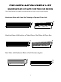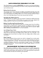
1
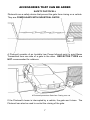
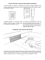
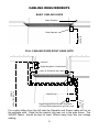
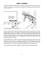
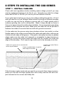
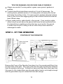
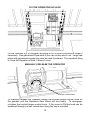
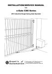
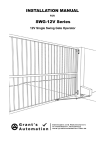
installation/service manual
FOR
e-Gate CSD series
24V Industrial Sliding Gate Operators for Gates to 800kg
Contents
pre-installation check list . . . . . .
1
maximum size of gate for the CSD series . . . . . . . . . . . . . . . 1
gate operator frequency of use . . . . . . . . . . . . . . . . . .
2
environment suitable for the operator . . . . . . . . . . . . . . . 2
important safety instructions! . . . . . . . . . . . . . . . . . . .
3
tools and hardware required . . . . . . . . . . . . . . . . . . . . 4
preparing the gate . . . . . . . . . . . . . . . . . . . . . . . . .
5
Guide Post clearance . . . . . . . . . . . . . . . . . . . . . . . .
5
automatic operator fitting requirements . . . . . . . . . . . . . . 6
accessories that can be added . . . . . . . . . . . . . . . . . . .
7
safety photocell
7
digital keypad and/or intercom
8
a Ground Loop vehicle Detector
8
Cabling Requirements . . . . . . . . . . . . . . . . . . . . . . . . . 9
Basic Cabling Guide
9
Full Cabling Guide
9
type and size of Cable
10
how it works . . . . . . . . . . . . . . . . . . . . . . . . . . . . . 11
8 Steps to installing the CSD series . . . 12
step 1 - install cabling . . . . . . . . . . . . . . . . . . . . . . .
12
Tips for running low voltage cable yourself.
13
step 2 - fIT THE OPERATOR . . . . . . . . . . . . . . . . . . . . . . . 13
Position of the Operator
13
fiX the Operator IN PLACE
14
manually release the Operator
14
step 3 - fIT THE RACK TO THE GATE . . . . . . . . . . . . . . . . . . . 15
step 4 - terminate cabling . . . . . . . . . . . . . .
19
SLD-24V-S General Wiring Diagram
19
checking the gate direction
20
terminating a photocell
21
terminating a light
21
terminating digital keypad, card access, Key switch or Press Button22
terminating ground loop vehicle detector
22
terminating a 7-Day timer, digital keypad or keyswitch
23
terminating an intercom
23
terminating seperate open, stop and close p/b’s
24
terminating emergence stop devices
24
step 5 - tune the Remote Controls in . . . . . . . . . . . . . . . .
25
remote control open, stop and manual close
25
remote control open with auto-close
25
removing remote controls
26
remote controlled pedestrian entry
26
user adding remote control at a later date
26
Step 6 - learn Gate open limit . . . . . . . . . . . . . . . . . . . . 27
Step 7 - activate and test accessories . . . . . . . . . . . . . . . 28
other options for control inputs28
Step8 - fine tune gate operator preferences . . . . . . . . . . . . 29
changing the Auto-close delay
29
changing the Photocell-close delay
29
changing the Pedestrian-close delay
30
changing up the Lock/Light Output
30
changing the level of soft start and soft stop 31
changing the gate obstruction sensitivity
31
return to factory settings . . . . . . . . . . . . . . . . . . . . . 32
recommended maintenance schedule . . . . . . . . . . . . . . . . 33
maintenance check list . . . . . . . . . . . . . . . . . . . . . . . 34
maintenance history . . . . . . . . . . . . . . . . . . . . . . . . 34
accessories available . . . . . . . . . . . . . . . . . . . . . . . 35
trouble shooting . . . . . . . . . . . . . . . . . . . . . . . . . . 35
warranty . . . . . . . . . . . . . . . . . . . . . . . . . . . . . . 36
pre-installation check list
maximum size of gate for the CSD series
If this Gate Operator is installed on a gate that is too Heavy it may not work properly.
2m High
1.8m High
Aluminium Gates with Open Bar Cladding or Pipe and Chain Link
300mm rise
20m Wide
12m Wide
1.8m High
1.8m High
Aluminium Gates with Aluminium or Timber Slats or Steel Gates with Open Bars
150mm rise
12m Wide
8m Wide
1.2m High
2m High
Steel Gates with Hardwood Slats or Solid Hardwood gates
12m Wide
6m Wide
1
gate operator frequency of use
This Gate Operator is rated for industrial use, which is any Housing Estates,
Commercial or Industrial Building Car Parks or Entry ways that have anything
up to continuous use.
Battery Back Up System
This operator has a 24V 7Ah back up battery as standard that take over if the
mains power fails. It will provide up to 200 operations for light weight gates or
up to 100 operations for 800kg Gates over a 4 hour period or last up a day or
more if not used depending on how manu accessories are fitted.
Upgrading the Battery Back Up
The Battery Back Up capacity can be increase if desired by adding extra batteries. If using more than a 20Ah battery its a good idea to also upgrade the
charge regulator to improve recovery time it batteries are run flat.
Battery Conditioning During Normal Use
During normal use when the motor starts up it draws power from the battery,
which keeps it conditioned for reliable operation as batteries need to be used
regularly for them to work properly. This also means that the operator must
have a battery connected before it will work properly.
Low Voltage Power Cable
The Battery Conditioning arrangment also allows the power transformer to be
away from the gate and Low Voltage Power Cable only run to the gate. This
is because any current that is too high for the low voltage cable is taken up by
the battery.
Solar Powered
Run from the Battery during normal use, which is charged from a solar panel.
They need at least a 100Ah battery to run for up to 300 operations per day for
10 days straight with no charge. The solar panel needs to be large enough to
recharge the battery in full sun in three days or longer if cloudy. A 24V 80Watt
solar panel will do this. This also requires a larger charge regulator, a 24V 6A
or larger is required.
environment suitable for operator
The CSD series is suitable for outdoor use so long as it is NOT exposed for
long periods to saltly air or other corrosive substance or contaminents that may
cause fouling of the gate, gate operator, any of the gate operators components
or accessores that may be connected to the operator.
2
important safety instructions!
CONSIDERING THE GENERAL PUBLIC:
When Installing an Automatic Gate that will be entered from a public road
way, make sure the Gate is placed far enough from the road to prevent traffic
congestion.
The Gate must be installed in a location that provides adequate clearance
between it and adjacent structures when opening and closing to reduce risk of
entrapment. Swing gates must not open into public access areas!
Install the Gate Operator on the inside of the property and fence line. DO NOT
install an opener on the outside of the gate where the public has access to it.
The Gate and Gate Operator must comply with any applicable local council
regulations.
CONSIDERING THE USERS:
Industrial Gate Operators must use Point to Point Safety Photocells to help
prevent the gate closing on any vehicle using the gate.
It is also recommended that a seperate small side gate is used for pedestrians
particularly if there will be children, disabled or elderly people using the gate.
If push buttons, key switches or Digital Keypads are installed, they should be
within sight of the gate but not placed so the user will be tempted to reach
through the gate to activate the gate operator.
USER AWARENESS:
It is important to make sure everyone that will be using the gate is aware of the
following dangers associated with automatic Gates: do not contact any part of
the gate or walk in the path of the gate while it is moving. Never let children
play with the gate controls. Do not attempt to “beat the gate” while it is closing.
This is extremely dangerous.
In the event you sell the property, make sure the new owners have a copy of
these instructions. If you lose the instructions they can be downloaded from:
www.grantsautomation.com.au.
3
tools and hardware required
The tools you’ll need include:
A basic set of hand tools will be needed including: side cutters, pliers, wire
strippers, a range of phillips head screw drivers, a small flat head screw driver
for terminal block screws and a socket set.
You’ll also need a tape measure, marking pen, an elecric drill with hammer
action and variable speed control, a 10mm hammer drill bit and socket bit for
10mm or 3/8” tek screws. An angle grinder is also handy although a hacksaw
will do if you don’t have one.
If you intend on doing you own low voltage cabling a pair of conduit cutters
are handy although a hacksaw can also be used. If you wish to run cabling
across the driveway you will need either a 230mm angle grinder with masonary
grinding disc or a hand held concrete cutter. You can hire these if necessary.
If you’ll be running cabling across a lawn or garden you’ll need a spade and
mattock for digging a low trench. If it’s a long run then a small trench digger can
be hired to do the job.
YOU MAY ALSO NEED THESE ITEMS BEFORE INSTALLATION
For systems with accessories added Low Voltage Cable is required see
“Cabling Requirements” for more information.
You may also need conduit, which is available from Electrical trade
suppliers and hardware stores.
For Mains Powered Systems you will need a mains power point mounted on a
free standing post in front of the gate next to automatic operator. Check with
local regulations before installing a mains voltage power point yourself, you may
need a registered electrician to do this for you.
4
preparing the gate
Guide must
move easily
for entire
length of
gate.
The Keeper/
Hard Stop to
be aligned
to the gate
correctly
Must also
have a Hard
Stop for the
Open Limit
Gate must be Straight
not twisted or bowed.
Gate Track must be Straight,
gate should not run or catch
on the track.
Gate Operator on a
level concrete pad
Make sure that the gate has been properly installed, is straight and slides freely
throughout its entire length without any grabbing from the guides or track any
where along the gate. The gate track must be in a straight line any
sudden dips or rises may prevent the gate operator from being installed properly.
Repair or replace all worn or damaged gate hardware prior to installation. Gate
posts less than 150mm wide should be made from steel not timber. Replace
posts where necessary. A freely moving gate will require less force to operate
and will enhance the performance of the operator and give a long working life.
The operator should be well drained and not be submersed in water or have
water running past it in heavy rain.
Guide Post clearance
If using a guide post behind a gate
allow at least 60mm clearance for
the Rack. If the guide is fitted to the
front Fence or Wall the clearence
has no effect so long as the Gate
does not contact it at all.
Front
Fence or
Wall
Rear
Guide Post
if used
Gate
60mm
5
automatic operator fitting requirements
Driveway
Guide
Post if used
Extra Gate Length
for Automatic
Operator
400mm
Front Fence/Wall
Gate
Concrete
Pad
500mm
Lawn or Garden
Concrete Footing and Pad
250mm
Gate
Operator
Driveway
400mm
Concrete Pad
600mm
Lawn or Garden
Conduit for Power Cable
to come out of concrete
pad here if Power is
Hardwired.
Plan View
The Gate Operator requires a level concrete pad to mount on. Even if the driveway is sloping the
concrete pad for the Operator MUST BE LEVEL!. The concrete pad should no less than 100mm
thick and after concrete is poured it must be given a week or so to harden before the operator is
installed.
If the Gate Operator power is to be hard wired it’s a good idea to place a piece of conduit into the
concrete pad, during installation, for the power cabling later on.
Extra Gate
Length for
Automatic
Operator
need only be the
bottom rail
front VIEW
Gate track and footing must
be straight but can be on a
gentle slope
Gate
Driveway
Concrete Pad must be level
even if gate track isn’t
6
Concrete Pad must be well
drained and not ever be sitting
in water even after heavy rain
accessories that can be added
safety photocell
Photocells are a safety device that prevent the gate from closing on a vehicle.
They are compulsary with industrial gates
A Photocell consists of an Invisible Low Power Infrared point to point Beam
Transmitted from one side of a gate to the other. REFLECTOR TYPES are
NOT recommended for outdoors.
A Photocell prevents a Gate from Closing on a car
If the Photocell’s beam is interrupted by a vehicle, the gate won’t close. The
Photocell can also be used to control the closing of the gate.
7
digital keypad, card access and/or intercom
To allow access to visitors or tradesman any brand of digital keypad, Card
Access system and/or intercom can be installed (provided the intercom has a
door release feature).
A Digital Keypad or Proximity Card An Intercom allows visitors to call the
System allows access to anyone with house and speak with the occupier. If
the correct pin number or card.
the occupier wishes to let the visitor in
they can press a button on the intercom
inside to open the gate.
a Ground Loop vehicle Detector
Loop of wire in
driveway used to
detect vehicles
A ground loop in the driveway detects any vehicles approaching the gate and
opens it automatically to let them out. Pedestrians cannot use the ground loop
to open the gate, which is a safe guard from anyone jumping the fence.
8
Cabling Requirements
Basic Cabling Guide
Open Direction
Gate Operator
To Power
Source
Full Cabling Guide Right hand gate
Intercom
Digital Keypad or Card Access
Photocell
Gate Operator
Digital Keypad,Card Access, Keyswitch
or Press Button(alternate to ground Loop)
To Power
Source
To Intercom Inside
station
Ground Loop
For a gate sliding from the left side the Operator and Power cable will be on
the opposite side. Cable for the electric lock may run in the gate frame. The
240VAC Mains should be kept at least 100mm away from any low voltage
cabling.
9
type and size of Cable
240V Mains at Gate
Mains power is best hard wired to the operator. If an outdoor power point is
used the can be turned off so is NOT recommended. You will need a registered
electrician to do this for you.
Low Voltage Systems
Don’t need a register electrican because all power at the gate is 24V. A plug in
transformer is supplied that can plug in anywhere there is power or can be hard
wired by an electrician. Low Voltage Garden Lighting Cable only is required
between the transformer and the gate operator. 2mm2 cable is good for up to
25m and 4mm2 for up to 50m.
For Accessories
0.4mm Diameter (0.12mm2) or 0.65mm Diameter (0.33mm2) Outdoor telephone
cable is ideal for Connecting Photocells, Digital Keypads and Intercoms as this
cable has a tough outer sheath and is gel filled to protect it from moisture. Cat
5e and indoor phone cable is fine to use so long as it isn’t exposed to moisture
for prolonged periods. If using security cable this must be a conduit that is fully
sealed to prvent any exposure to moisture.
10
how it works
The SLD-24V-IND-S Gate Operator consists of an electro-mechanical drive unit
with built in electronic controls that connects with racking on the gate driving it
open or closed.
Gear Wheel from
Operator drives
Rack on Gate
When the Operator is activated by remote control or other control device, it drives
the gate open or closed. A toothed rack is fitted to the gate that engages with an
output Gear Wheel on the operator. Hard stops are used to determine the open
and close limits of the gate. The electronic controls also continually monitor the
loading on the gate when ever it is operating so if the gate is obstructed it will
reverse direction for safety.
Limit switches with are NOT used with Industrial sliding gate operators as the
strike plate on the Rack is a target for Vandals and Limit Switches that work
within the operator can get out if the gate jumps a cog. This operator ramps the
speed down for a soft stop and applies a light pressure to the hard stop.
The operator has an electric brake to prevent the gate being forced open.
11
8 Steps to installing the csd series
step 1 - install cabling
Check with local regulations before installing mains voltage yourself, you may
need a registered electrician to do this for you. Normally any cable for voltage
lower than 32VAC or 50VDC you can do your self without a license.
If your gate track is hollow you can run low voltage cabling through this. If it isn’t
and you need to run Low Voltage Cable across a concrete or bitumen driveway
or path you can do this by chasing a groove with a 9” angle grinder with a
masonry grinding disc (not a cutting disc). Make it deep enough so there is
5mm or so space above the cable when installed. Use an expansion gap where
possible as this requires less work. Make sure the cable will not be pinched if
between two slabs of concrete that can shift with ground movement.
Fix the cable into the groove using clear plumbers silicon (non acidic) or other
flexible sealer in the clean groove before the cable and again after, making sure
it sticks to both sides of the groove. If the path or driveway has lawn or garden
edges make sure the cable isn’t exposed or accessable to edge trimmers or
spades by running the groove down the edge and into conduit just under the
edge of the driveway. You’ll need to dig a hole next to the driveway to do this.
Cable run in groove cut in concrete with
silicon top and bottom
If lawn or garden edge, run groove
down edge of concrete
Conduit runs under Path to
keep it safe
Dig hole at edge of concrete
If the driveway meets a post and you need to go around it then chase a groove
where you can with the angle grinder then use a rotary hammer drill as a mini
jack hammer for the corners and fiddly bits.
12
Tips for running low voltage cable yourself.
Always use conduit if running cable in grass, open ground, gardens or
pebbles.
Conduit should be buried deep enough so it is out of harms way. For
existing lawns, pebbled areas or if run along side a driveway then buried
just below the surface is fine. For open ground, gardens and area’s where
there is likey to be other digging going on then conduit should be buried at
least 300mm deep.
Never make joints in cable directly in the ground. If you must join cable,
either bring it up well above the ground and have the joint protected from
the elements by a weather proof junction box or put a pit in the ground
to make sure the joint is sitting in the air within the pit and cannot be
submerged in water.
step 2 - fIT THE OPERATOR
Position of the Operator
60mm from back
face of gate
Open and Close the Gate
to check straightness
Gap must
not vary
more than
5mm as
gate open
and closes
Remove the Cover of the Operator then place it on it’s concrete pad 60mm from
the back face of the gate. Then open and close the gate checking this distance
from the operator as you go. It should not vary more than 5mm each way from
fully open to fully closed other wise the gate and/or track is not straight enough
and the gear wheel may not contact the rack well enough.
13
fiX the Operator IN PLACE
Fix the Operator to it’s Concrete Pad using M10 x 50mm Dyna bolts or longer if
necessary. Use galvanised Dyna bolts if you can so they won’t rust. Large raw
plugs and galvanised screws may also be used if prefered. The important thing
is, once the Operator is fitted, it doesn’t move.
manually release the Operator
Torque Control Knob
To manually release the Operator loosen the knurled torque control knob on
the gearbox until the Operators Gear Wheel will turn freely. To re-engage,
re-tighen the knurled torque control knob. If the cover is ON this knob can be
accessed through a small locked door using the key is provided.
14
step 3 - fIT THE RACK TO THE GATE
Before fitting any rack, lay it out in front of the closed gate to see how it lines
up. Start at the operator end, with the first length sitting on the operators gear
wheel, adjusting the position of the rack as you go to make sure the mounting
lugs miss the wheels. If the last length needs to be cut shorter, it must have at
least two mounting lugs attached to the gate.
1) Start with the Gate Closed and the first
length of rack just overlapping the Gear
wheel, mark this position, then add more
lengths until the end is reached.
2) Make sure mounting
lugs miss the wheels
3) Last length of rack may need to be cut shorter,
if so it must have at least two mounting lugs on
the gate. If this isn’t possible then all the rack
may need to be moved back a bit and the first
length may also need to be cut.
4) Mark on the gate where the last
length will finish (after cutting).
OPEN FULLY
5) Open Gate by hand and use the
new mark to check the rack contacts
the Gear Wheel when fully open, if not
it will need to be adjusted.
This gate operator has no limit switch strike plates or magnet on the rack so the
rack need only overlap the dear wheel by a small amount.
15
Tek Screw in
centre of slot
To fit the Rack, start with the gate nearly closed and place the first length of rack
on the Operators Gear Wheel, in line with the mark you made earlier and the
bottom rail. Drill two 10mm (or 3/8”) Tek screws into mounting lugs for the rack,
making sure they are both in the centre of each slot. Use only two and do not
fully tighten at this stage, as the height of the rack needs to be adjusted.
1mm
Move the gate by hand until each of the Tek screws are aligned with the gear
wheel and adjust the height of the rack until it has about 1mm clearance above
the gear wheel. Tighten the tek screws fully once the height is correct.
16
Drill Tek screw in on
an angle to close gap
between lengths of
rack
2nd Length Slotted
into the first
Now fit the 2nd length of rack by sliding the gate open a bit further and placing
it so one end is slotted into the first length and the other end is sitting on the
operators gear wheel, allowing enough room to drill another tek screw in. Drill
the tek screw in on an angle to close up any gap between the two lengths.
Should Run Smoothly over the joint between lengths of rack
If the gate is now moved by hand and run over the join between the lengths of
rack, there should be no jump, it should run smoothly over the join. Also set the
1mm clearance at the new tek screw position and tighen it up fully. Repeat the
same with the remaining lengths of rack, just tacking them all in place for now
with two tek screws.
17
Once all lengths are tacked in place and the gate is opened and closed to
check the rack contacts the gear wheel at all times then cut off any access rack
using an angle grinder or hack saw. The Rack may be plastic on the outside
but it has a steel rod in the middle.
Now go through and tek screw all mounting lugs for the rack that haven’t
been done yet, adjusting the 1mm clearance from the gear wheel as you go. It
is quicker to do these all in one run.
18
step 4 - terminate cabling
csd series General Wiring Diagram
N.O. RELAY
OUT FROM
INTERCOM
or PRESS
BUTTON
12V LOCK
OUT FROM
INTERCOM
12V Relay
V+
GND.
COM
N.O.
N.C.
These Jumper Shunts overide the normally closed inputs, REMOVE
ONLY ONCE GATE LIMITS ARE SET
Learn P/Bs
Learn P/Bs for
for Limits and
Remote Controls
Preferences
Antenna
Sheild
OSC P/B
+
ANT
GND
OSC
OPEN
STOP
PC
CLS
PED
GND
24V+
Digital
Keypad
GDN
V+
COM
N.O.
N.C.
Motor 1
has Ped
entry mode
240VAC
Mains Supply
P N E
Chassis
Ground
DC IN -
DC IN +
LOCK/LIGHT -
LOCK/LIGHT +
ACT+
Motor 2 for
Bi-Parting
Gates
Black
Red
ACT-
GND
V+
COM
N.O.
N.C.
Photocell
Transmitter
V+
GND
ACTACT+
Loop
Detector
These Shunts must be in place as no
limit switches are used
Black
Red
Photocell
Receiver
GND
V+
COM
N.O.
N.C.
CTRL-GP-24V-S Control Board
Electric
Brake(s)
24V Battery
Charge
Regulator
Unit
35A
Diode
24VAC or
Solar Input
35A Rectifier Unit
24VDC output
240V - 22V 160VA Transformer may be external
19
+
24V Battery
checking the gate direction
The Gate Operator is prewired for a Left Hand Gate.
OPEN DIRECTION
LEFT HAND GATE
If you have a Right Hand Gate then you’ll need to change the Motor Power
wires around.
OPEN DIRECTION
RIGHT HAND GATE
EN+
ENENS
For Right Hand Gates change the Red and Black
Motor Power wires around so the gate will travel in
the opposite direction.
Black
Red
ACTACT+
e-Gate Control Board
Motor
The terminal blocks on the control
board unplug to allow easier and better
connections.
Make sure all strands of the wire are tightly
held by the terminal block. Stray strands can cause a short circuit.
20
terminating a photocell
Safety Photocells use a ‘normally closed’ connection to the control board. If
the photocells light beam is broken by a vehicle while the gate is closing it will
be reversed back open again. The gate will not close until the photocell light
beam is remade and vehicle is clear. If a photocell closing delay option is
activated (DIP 3 ON) the gate will begin to close once the photocell close delay
has timed out rather than the auto-close delay.
PC
GND
24V+
Photocell
Transmitter
GND
V+
Photocell
Receiver
GND
V+
COM
N.O.
N.C.
terminating a light
By connecting a 24VDC relay to the gate operator it can also activate lights for
1 or 4 minutes when ever the gate is opened. See “Changing the LOCK/LIGHT
output” section in Step 8 for information on how to change this.
LIGHT -
24VDC
Relay
V+
GND.
COM
N.O.
N.C.
21
LIGHT+
POWER
SOURCE
FOR
LIGHT
LIGHT
either
continuous
or self
flashing
terminating digital keypad, card access, Key switch or Press Button
A Digital Keypad, Card Access System, Key switch, Press Button or any other
clean contact normally Open (NO) device can be used to activate the gate. If
a Digital keypad has two or more relay outputs, then these can be used for
different operational functions such as open with manual close, open with autoclose or Pedestrian only access with auto-close.
24V Digital
Keypad or
Card Access
System
GND
V+
COM 1
N.O. 1
N.C. 1
COM 2
N.O. 2
N.C. 2
COM 3
N.O. 3
N.C. 3
OSC
OPEN
PED
GND
24V+
Key
Switch or
Press
Button
terminating ground loop vehicle detector
A ground loop must be used with a photocell to control the opening and closing
of a gate. If a vehicle wishing to exit drives over the ground loop the gate will
open. If the vehicle remains over the ground loop or the photocell light beam
is broken the gate will remain open. Once both are clear the gate will autoclose normally or if the photocell closing control is active (DIP 3 ON), will close
immediately or can be delayed. For incoming vehicles sharing the same gate
the photocells closing control is inherited by the ground loop.
Wire Loop
set in
driveway
Twisted Pair from Wire
Loop in Driveway
OPEN
24V Loop
Detector
GND
V+
COM
N.O.
N.C.
22
GND
24V+
terminating a 7-Day timer, digital keypad or keyswitch to
hold the gate open.
A 7-Day Timer, Digital Keypad, Key switch or any other clean contact normally
closed (NC) device can be used to hold the gate open. Because this is a
normally closed connection all devices must be OFF (contact closed) before the
gate will close. To hold the gate open any one device must remain ON (contact
open). Gate closure will occur once all contacts are closed and the auto-close
delay has timed out.
34V 7-Day
Timer
GND
V+
COM
N.O.
N.C.
OPEN
24V Digital
Keypad
GND
V+
COM
N.O.
N.C.
GND
24V+
COM
Key
N.O.
Switch N.C.
terminating an intercom
Intercoms also use a normally open connection to the control board. Intercoms
will either have a relay output with clean contacts or provide 12VAC or 12VDC
to directly operate an electric strike lock. The later requires a relay, available as
an accessory and will work with both 12VAC or 12VDC.
INTERCOM WITH
12VAC or 12VDC
OUTPUT for
Electric Strike Lock
+
INTERCOM
WITH
RELAY
OUTPUT
COM
N.O.
N.C.
12VAC/DC
Relay
V+
GND.
COM
N.O.
N.C.
OSC
GND
23
terminating seperate OPEN, STOP and CLOSE p/bs
With some Industrial Applications it may be necessary to have three seperate
Press Buttons for Opening, Stopping and Closing the Gate.
NO P/B
NC P/B
OPEN
OSC
STOP
STOP
CLOSE
CLS
DIP
Switch
4 ON
GND
terminating emergency stop devices
For Industrial gates exposed to the general pedestrian
traffic it is a good idea to install emergency stop
photocells in area’s or possible entrapement or an
emergency stop press button for staff.
EMERGENCY
STOP (NC P/B)
STOP
GND
24V+
Photocell
Transmitter
V+
GND
Photocell
Receiver
GND
V+
COM
N.O.
N.C.
powering up for the first time
Before you can go any further you must Power the Gate operator up for the first
time. Make sure the control board input shunts are ON. Then plug the Batt/
DC IN terminal in.
24
step 5 - tune the Remote Controls in
If the on board receiver is used (not a stand alone receiver)
Button A is the main button on the remote control
for opening the gate. The other buttons can be
used for other options or opening a garage door
(e-Gate RX-1 receiver required).
Each remote control transmits a unique digital
code. Before the control board can respond, it
must first learn this code and know what action
to take.
Remote Control with OPEN, STOP and Manual Close
At the top right hand corner
of the Control Board are
three press buttons used for
Learning the remote controls
codes for different actions.
OSC
OPEN
PED
OSC P/B
For Opening the gate with
Manual Stop and Close Press
the “OSC” Learn Button, a
beeper will start beeping, then
press a button on the remote
control within range of the gate
and the beeper will beep more
rapidly for a second to confirm it has been learned. This button should now
operate the gate. Repeat the same with all remote controls.
Remote Control open with Auto-close.
If you do as above but use the “OPEN” Learn Button, the remote control will now
open the gate only and it will close automatically after auto-close delay or close
with an OSC or CLOSE input.
You can use one remote control button to open the gate with manual close
(OSC) and a second with auto-close (OPEN) if you like. Button A is handy to
have with open only and auto-close for normal use and button B with Open,
Stop and Manual close in case you want to back a trailer in and don’t want the
gate closing on you.
The control board can Learn up to 60 seperate remote control buttons.
25
Removing Remote Controls
To remove one remote control button press the OSC LEARN button, a beeper
will start beeping, then press the already learned remote control botton you wish
to remove, the beeper will beep more rapidly for a second to confirm removal.
If you don’t have the remote control then you must remove all remote controls
and re-Learn the ones you have. If you have a lot of remote controls then
consider using the RX-Mega stand alone receiver as it can learn up to 1000
remote controls and individual remote controls can be removed even if it has
been lost.
To remove all remote controls press and hold OSC LEARN button for more than
10 seconds (beeps) and the beeper will beep more rapidly indicating that all
remote controls have all been removed.
Remote Controlled Pedestrian Entry
If your automatic gate is the only way in or out of your property you can allow user
access on foot only, by having the remote control open the gate part way and
closing automatically after a pre-set delay. This delay can be set independantly
from the vehicular entry auto-close delay see “Changing the Pedestrian-close
Delay” section in step 9.
Use the “PED” Learn Button on the control board and any unused button on
the remote control as you did above. To set the amount the gate will open see
Step 7.
user adding remote controls at later date
If you have at least one remote control that operates your gate you can use this
to tune in new remote controls without having to open the control box up. This
is done by pressing combinations of buttons together on the working remote
control within range of the gate. Pressing Buttons A and D together is the same
as pressing the “OSC” Learn Button on the control board, A and C together is
the same as pressing the “OPEN” Learn button and B and D for “PED” Learn
Button. Once you press any of these combinations you’ll hear the beeper in the
control box beeping. You can now press a button on a new remote control to
get it to operate the gate.
Remote control buttons can also be deleted from memory this way. As a safe
guard not all remote control buttons can be deleted, using this method, there will
always be one left working, so the end user can’t accidently delete them all and
not know how to get it working again.
26
Step 6 - learn Gate open and close limits
The gate must have a suitable hard stop in the open and close position as this
not only prevents the gate from coming off the guide it also sets the open and
close limits. But the operator must know how long the gate takes to open so it
knows when to start ramping down for slow stop and reverse if obstructed while
operating.
Top RH corner of control board
LEARN
All DIP
Switches
OFF
Top LH corner of control board
OSC P/B
The ‘Learn Open Time’ function must be
run on the control board before the operator will work properly.
If you wish to use the Pedestrian
entry feature then start by opening the gate
by the desired amount using the OSC P/B on the
control board, other wise any position will do.
To start the LEARN function make sure
all DIP Switches are OFF then press the LEARN
button and the Beeper will start beeping. Now press
the OSC P/B on the control board or remote control
to start the function running.
Once started the gate with motor 1 will start
closing slowly as it searches for the close stop then
if it’s a Bi-Parting Gate it will do the same for gate
with motor 2.
When it finds A close stop it will beep
rapidly for a second to confirm then start opening to find the open STOP.
Once the open stop is found the controller will beep rapidly for
a second to confirm then if its a Bi-Parting gate repeat the same for the other
motor then once this is complete go back to normal operation leaving the gate
open.
The controller will remember the open and close
limits from this time on, even if the power is removed from the operator.
During normal operation each the gate will always slow down just before the
Hard Stop and drive gently against it.
27
Step 7 - activate and test accessories
Any intercoms, key switches, press buttons or digital keypads connected to
the OSC, PED, or CLOSE inputs can now be tested. The OSC input opens,
stops and closes the gate. The PED input opens the gate part way, then will
close automatically after the Ped-close delay. The CLOSE input closes the gate
only.
Any devices connected to the OPEN, STOP or PC inputs require their shunt to
be removed before they will be active. The open input opens the gate, will hold
it open while ON and will close automatically after auto-close delay once OFF.
The STOP input will stop the gate in any direction when ever it is moving. The
PC input will reverse the gate while closing only and hold it open while it remains
ON and will close automatically after close delay once OFF.
other options for control inputs
These Shunts overide the normally closed inputs
LEARN
ANT
GND
DIP
Switches
OSC
OPEN
STOP
PC
CLS
DIP 1 ON - activates autoclose function for the OSC
control input or any remote
control button that has been
activated for OSC operation.
Gate will close after preset
auto-close delay.
DIP 3 ON - allows the
Photocell(s) to control closing
of the gate immediately or
after a preset Photocell-close
delay - default delay is 2
seconds
DIP 4 ON - changes the OSC
input so it can open the gate
only. Ideal when there is a
lot of users. Must be used
with auto-close or the Close
Control input to close the
gate.
PED
GND
24V+
DIP 5 ON - deactivates the
auto-close feature for the
OPEN only control input.
This can be handy for some
commercial installations.
28
DIPs 2, 6, 7 and 8 are spare
and can be used to select
special features that may be
programmed into the control
board.
Step 8 - fine tune gate operator Preferences
The DIP Switch and Learn Button have a secondary purpose, which is to make
changes to the Control Boards preferences. Once the preferences have been
set the DIP switches should be returned back to the way the were for normal
operation.
changing the Auto-close delay
Top RH corner of control board
LEARN
DIP
Switch
1 ON all
others
OFF
With DIP Switch 1 only ON, press the LEARN
button and the Beeper will start beeping, it is not
necessary to hold the LEARN button. Now wait
for the desired Auto-close time and press the
LEARN button again. The Beeper will beep more
rapidly for a second to confirm the new delay has
been learned.
The Beeper beeps once a second, so if you count
the beeps you are counting seconds, handy if you
want an exact time.
If you leave it beeping it will time out after 4 minutes
and set this as the auto-close delay.
changing the Photocell-close delay
Top RH corner of control board
LEARN
DIP
Switch
3 ON all
others
OFF
With DIP Switch 3 only ON, press the LEARN
button and a Beeper will start beeping, it is not
necessary to hold the LEARN button. Now wait for
the desired Photocell-close delay and press the
Learn button again. The Beeper will beep more
rapidly for a second to confirm the new delay has
been learned.
The Beeper beeps once a second, so if you count
the beeps you are counting seconds, handy if you
want an exact time.
If you leave it beeping it will time out after 4 minutes
and set that as the delay.
29
changing the Pedestrian-close delay
Top RH corner of control board
LEARN
DIP
Switch
4 ON all
others
OFF
With DIP Switch 4 only ON, press the LEARN
button and a Beeper will start beeping, it is not
necessary to hold the LEARN button. Now wait for
the desired Pedstrian close delay and press the
Learn button again. The Beeper will beep more
rapidly for a second to confirm the new delay has
been learned.
The Beeper beeps once a second, so if you count
the beeps you are counting seconds, handy if you
want an exact time.
If you leave it beeping it will time out after 4 minutes
and set that as the delay.
changing the Lock/Light Output
Top RH corner of control board
LEARN
DIP
Switch
5 ON all
others
OFF
There are 6 modes of operation for the Lock/Light
output including:
1.Strike Lock - comes ON for 2 seconds on open
2.Light timer 1 - comes ON for 1 minute on open
3.Light timer 4 - comes ON for 4 minutes on open
4.Open indicator - comes ON when gate is open
5.Brake mode - comes ON when gate is moving
6.Clamp mode - comes ON when gate is closed.
The factory setting for the Lock/Light Output is mode
2 for a light timer of 1 minute.
With DIP Switch 5 only ON, press the LEARN button and the control board
will beep out the current mode ie. if the mode is 3 there will be 3 beeps, then
there will be a pause for 2 seconds and it will start beeping again. This is when
you can change the mode by pressing the Learn button at the desired beep ie.
if you want to change it to mode 5 then press the Learn button during the 5th
Beep. The control board will beep more rapidly to confirm the new setting .
If you change your mind half way through just don’t press the Learn button
again and it will time out after 6 beeps and no change will be made.
30
changing the level of soft start and soft stop
Top RH corner of control board
LEARN
DIP
Switch
6 ON all
others
OFF
There are 16 levels of Soft Start/Stop numbered from
1 to 16. The factory setting is 8, 1 being least and 16
being the most.
With DIP Switch 6 only ON, press the LEARN
button and the control board will beep out the current
level ie. if the level is 3 there will be 3 beeps, then
there will be a pause for 2 seconds and it will start
beeping again. This is when you can change the
level by pressing the Learn button at the desired beep
ie. if you want to change it to level 5 then press the
Learn button during the 5th Beep. The control board
will beep more rapidly to confirm the new setting.
If you change your mind half way through just don’t
press the Learn button again and it will time out after
16 beeps and no change will be made.
changing the gate obstruction sensitivity
If the gate is obstructed while operating it will stop
Top RH corner of control board
and reverse away. There are 6 different levels of ObLEARN
struction Sensitivity for the gate numbered from 10 to
16. The factory setting is 12 with 10 being the most
sensitive and 16 being the least.
DIP
Switch
7 ON all
others
OFF
With DIP Switch 7 only ON for motor 1 and * for
Motor 2, press the LEARN button and the control
board will beep out the current level ie. if the level is
12 there will be 12 beeps, then there will be a pause
for 2 seconds and it will start beeping again. This is
when you can change the level by pressing the Learn
button at the desired beep ie. if you want to change
it to level 15 then press the Learn button during the
15th Beep. The control board will beep more rapidly
to confirm the new setting.
If you change your mind half way through just don’t
press the Learn button again and it will time out after
16 beeps and no change will be made.
31
returning to the factory settings
Top RH corner of control board
LEARN
All DIP
Switches
ON
If you get into trouble and want to return everything
back to the way it was before you started you can
restore the factory settings by turning ALL DIP
Switches ON and pressing the LEARN Button. The
beeper will beep rapidly for a second to confirm the
factory settings have been restored.
This function resets everything including: removing
all remote controls and resetting the Gate Open
Limit.
You must turn the DIP Switches OFF again before
proceeding further.
32
Recommended Maintenance Schedule
Maintenance Schedule depends on frequency of use as follows:
Cycles per dayMaintenance Period
Over 150
.
100 to 150
.
.
50 to 100
.
.
.
.
.
.
.
.
.
.
.
.
.
.
.
.
.
.
.
.
.
.
.
.
.
.
.
. each Month
.
.
every 2 months
.
. every 4 months
20 to 50
.
.
.
.
.
.
.
.
.
.
.
.
every 6 months
up to 20
.
.
.
.
.
.
.
.
.
.
.
.
every 12 months
Maintenance checklist
Use the following Checklist for Scheduled Maintenance of the CSD Series Gate
Operator
•
•
•
•
•
•
•
•
•
•
•
•
•
•
•
•
Gate Hinges in Good Condition and Lubricated
Gate Swings Freely with suitable clearance from ground/posts.
Gate Hard Stops in good condition
Gate Operator and gate mounting bracket bolts/nuts are tight
All arm joints loose but firm
No oil leaks from gear boxes
Gear box drive cogs tight on shafts
Gear box mounting bolts/nuts tight
Manual release/torque limiter works correctly
Inside operator clean from insects, animal droppings, spider webs etc...
‘Baygon’ Surface spray around operator (not on electronics)
Chain lightly oiled
All Electrical Connections tight
Access/Exit control devices work properly
External Safety devices work properly
Check all components for corrosion
33
Maintenance history
Site Name .......................................................... Access Code.......................
Site Adress........................................................................................................
Date:Serviced by:Comment:
..................... .............................................................................................
..................... .............................................................................................
..................... .............................................................................................
..................... .............................................................................................
..................... .............................................................................................
..................... .............................................................................................
..................... .............................................................................................
..................... .............................................................................................
..................... .............................................................................................
..................... .............................................................................................
..................... .............................................................................................
..................... .............................................................................................
..................... .............................................................................................
..................... .............................................................................................
..................... .............................................................................................
..................... .............................................................................................
..................... .............................................................................................
..................... .............................................................................................
..................... .............................................................................................
..................... .............................................................................................
..................... .............................................................................................
..................... .............................................................................................
..................... .............................................................................................
..................... .............................................................................................
..................... .............................................................................................
..................... .............................................................................................
..................... .............................................................................................
..................... .............................................................................................
..................... .............................................................................................
..................... .............................................................................................
..................... .............................................................................................
..................... .............................................................................................
..................... .............................................................................................
..................... .............................................................................................
..................... .............................................................................................
34
accessories
TX-4 Extra Remote Controls for either 433.92Mhz (Blue) or 315Mhz (White)
RX-4 Stand alone Receiver - to allow a garage door or another brand of gate operator to be operated with the e-Gate remote control ether 433.92Mhz
RX-MegaStand alone receiver for a large number of users allows use of up to 1000 remote controls. A remote control can be deleted even if lost.
ANT-1 Antenna for remote control ether 433.92Mhz
Batt-TX Replacement Battery for TX-4 Remote control
Batt-7
Replacement Battery for Sliding Gate operator (2 required for 24V)
VCB-12Voltage Converter Board 16 to 24VAC/DC in and 12V 500mA out
RLY-12 Relay Board 12VAC/DC in and clean contacts rated at 60VDC/125AC 2A
RLY-24 Relay Board 24VAC/DC in and clean contacts rated at 60VDC/125AC 2A
PC-1 Photocell 12/24VAC/DC 15m outdoor
trouble shooting
Gate runs in the wrong direction - check the motor power wires are correct, if wired the wrong way
around the motor will travel in the wrong direction.
Gate runs for a short distance then stops - check the gate obstruction sensitivity or operator isn’t
being overloaded by a stiff gate.
Operator not working at all - check power cord or battery cable is plugged in. Check there is power
at the gate. Check fuse on the control board. Check input shunts are correct or control accessories
are working properly.
Operator running slowly - check the power and battery is connected properly and battery is charged.
A fully charged battery should be at 27.6VDC.
Gate won’t work when first powered up - check the OPEN, STOP and PC input cable connections
and shunts are correct and all accessories that may be connected are working properly.
OPEN, PC or STOP inputs won’t work - check the shunts for these inputs have been removed.
These shunts overide the inputs preventing them from working.
Remote control range is poor - check the antenna placement and connections. The antenna should
be as high as possible above any metal fencing, gates or posts.
35
warranty
a 12 Month Back to Base Warranty is offered by Grant’s Automation for any defect in a Gate
Operator System manufactured by Grant’s Automation or any third party component supplier to
Grant’s Automation due to faulty workmanship or materials causing the Operator to fail to work as
specified in this Installation and Service Manual.
Should any fault occur during the first 12 months after the operator was purchased, it should be
returned to the factory for repair or at the discretion of Grant’s Automation replacement at no charge
under the following conditions:
1. Proof of purchase is required ie. Invoice or purchase details recorded by Grant’s Automation.
2. If an operator is not installed immediately after purchase, at the discretion of Grant’s Automation,
the warranty may be extended to up to a maximum of 12 months after the date installed.
3. The operator has been installed and serviced according to this Installation and Service
Manual.
4. The operator has not been used for a gate larger, of a different type or higher frequency of use
than that specified in this Installation and Service Manual. The gate specifications are required
before any claims will be accepted.
5. The operator hasn’t been used in a highly corrosive environment or has been exposed to
contaminents that could cause the operator to fail.
6. The operator has not been used for purposes other that it was intended for.
7. The operator has not been tampered with or modified by any party not authorised in writing by
Grant’s Automation to do so.
8. The operator has not been damaged by any malicious act, accident, animals or adverse
weather conditions beyond the control of Grant’s Automation.
9. A reasonable amount of care with handling or using the operator has been be taken.
36