1
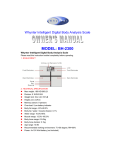
3900 Dental Chair Service Manual www.forestmed.com forest dental affordable excellence + designer friendly ™ 08-08-11 Rev.- 0097-381 COPYRIGHT ©2011 – BY FOREST DENTAL PRODUCTS INC. 6200 NE CAMPUS COURT, HILLSBORO OR 97124 PRINTED IN U.S.A. WARRANTY TRADEMARKS FOREST DENTAL PRODUCTS WARRANTS ITS PRODUCTS TO BE FREE FROM DEFECTS IN MATERIAL AND WORKMANSHIP ONLY. NO OTHER WARRANTIES ARE EXPRESSED OR IMPLIED. THIS WARRANTY SHALL EXTEND FOR FIVE YEARS UNLESS OTHERWISE STATED. W RITTEN NOTICE OF BREACH MUST BE GIVEN TO F OREST DENTAL PRODUCTS WITHIN THIS PERIOD. BUYERS REMEDY FOR BREACH OF THIS WARRANTY IS LIMITED TO REPAIR PARTS OR REPLACEMENT OF ITEMS BY F OREST DENTAL PRODUCTS INC. THIS WARRANTY IS VOID IF ITEMS ARE CARELESSLY USED OR IMPROPERLY MAINTAINED OR INSTALLED. T HIS WARRANTY DOES NOT COVER DAMAGE THAT RESULTS FROM USING CLEANING, DISINFECTING OR STERILIZATION CHEMICALS AND PROCESSES. THIS WARRANTY DOES NOT COVER LIGHT BULBS. HANDPIECE ILLUMINATION AND HEATED SYRINGE TUBINGS ARE WARRANTED FOR SIX MONTHS TO BE FREE FROM DEFECTS IN MATERIAL AND WORKMANSHIP ONLY. F ACTORY REPAIRS ARE COVERED FOR A PERIOD OF 90 DAYS. N O CLAIM FOR LABOR OR CONSEQUENTIAL DAMAGES WILL BE ALLOWED. FOREST LOGOS ARE REGISTERED TRADEMARKS IN THE U.S. PATENT AND TRADEMARK OFFICE. WELCOME W ELCOME TO THE 2011 EDITION OF THE FOREST 3900 DENTAL CHAIR PARTS AND SERVICE MANUAL. THIS MANUAL IS AN EASY TO USE SOURCE OF TECHNICAL INFORMATION FOR SERVICING THE FOREST MODEL 3900 DENTAL CHAIR. INTENDED AUDIENCE THIS MANUAL IS INTENDED FOR NEWLY TRAINED AND EXPERIENCED DENTAL EQUIPMENT REPAIR TECHNICIANS. WE ASSUME YOU UNDERSTAND THE OPERATION OF DENTAL EQUIPMENT AND CAN FOLLOW FLOW DIAGRAMS. TABLE OF CONTENTS P AGE OVERVIEW SERVICE AND SUPPORT LOCATING THE MODEL/SERIAL NUMBER POWER ON INDICATOR REMOVING AND INSTALLING CHAIR COVERS T HE HYDRAULIC SYSTEM FLOW DIAGRAM SERVICE PARTS SOLENOID MANIFOLD ASSEMBLY REMOVING A FAULTY SOLENOID INSTALLING A NEW SOLENOID ADJUSTMENTS CHAIR ELECTRICAL SYSTEM CIRCUIT BOARD DIAGRAM SERVICE PARTS T ESTING AND PROGRAMMING THE CHAIR SETTING HARD LIMITS PROGRAM CHAIR AUTO-POSITIONING FUNCTIONS RUNNING THE CHAIR SELF T EST T ROUBLESHOOTING ADJUSTING THE POSITION SENSING POTENTIOMETERS PARTS BREAKDOWN SPECIFICATIONS DIMENSIONS 4 5 5 6 7 8 9 10 11 12 13 15 16 17 18 19 19 23 25 26 33 35 39 40 Model 3900 Dental Chair OVERVIEW The Forest Model 3900 Dental Chair is an electronically controlled, hydraulically powered chair. The Touchpad and Footswitch are used to position the chair and program auto-positioning functions into the chair. The chair hydraulic system is controlled by the electronics using electro-mechanical relays and electrically powered solenoid valves. This section provides information related to locating the chair model/serial number, servicing the chair, troubleshooting, and adjustments that can be made to the chair. Service and Support Given the proper care, the Forest Model 3900 Dental Chair will provide years of trouble-free service. If something does go wrong with the chair and you are unable to correct the problem, call Forest Dental Products Customer Service 800.423.3555. When you call, be prepared to provide the following: 1. Serial number and, if known, the approximate date the chair was purchased. 2. Symptoms of the problem. 3. What steps you have taken towards correcting the problem. 8/8/2011 Rev. - 0097-381 Page 4 Model 3900 Dental Chair Locating the Model/Serial Number Power ON Indicator The model/serial number tag identifies the chair as being manufactured by Forest Dental Products and allows Customer Service to determine when the chair was manufactured. The date of manufacture is very important in determining the chair warranty status as well as the engineering revision. The Power ON Indicator, when illuminated, indicates that the chair has mains electrical power available. POWER ON INDICATOR SERIAL NUMBER TAG 8/8/2011 Rev. - 0097-381 Page 5 Model 3900 Dental Chair Removing and Installing Chair Covers The Forest 3900 chair motor pump, small arm cover and safety plate covers are removed as follows: 2 3910-030-SH 3 3912-031-G 3912-031-SH 4 Small Arm Cover, Shadow, 2” Hole for 1590 Umbilical Safety Plate, Gray, includes item 4 Safety Plate, Shadow, includes item 4 Safety Plate Retaining Screw Motor Pump Cover Using a 5/32” hex key, remove the two button head screws from each side of the cover and lift it. Small Arm Cover Using a 7/64” hex key, remove the four button head screws from the cover. Safety Plate Using a flat tip screwdriver, remove the single screw from the safety plate. The Safety Plate will drop when the screw is removed. Item 1 Part Number 3912-030-G 3912-030-SH 3912-011 3910-028-G 3910-028-SH 3910-029-G 2 3910-029-SH 3910-030-G 8/8/2011 Rev. - 0097-381 2 1 Description Motor Pump Cover, Gray Motor Pump Cover, Shadow Screw, Pump Cover Small Arm Cover, Gray Small Arm Cover, Shadow Small Arm Cover, Gray, 1-1/4” Hole for 1090 Umbilical Small Arm Cover, Shadow, 1-1/4” Hole for 1090 Umbilical Small Arm Cover, Gray, 2” Hole for 1590 Umbilical 3 Page 6 Model 3900 Dental Chair THE HYDRAULIC SYSTEM The hydraulic system consists of: Item Description A hydraulic fluid reservoir or tank that performs a number of functions in the dental chair hydraulic system: 1 • Fluid storage • Separation of air from fluid • Dissipation of heat • Settling of contaminants The fluid level in the reservoir can be seen through the sides of the reservoir; the reservoir is serviced via a top fill cap. 2 Hydraulic cylinders that convert hydraulic fluid pressure to mechanical movement lifting the chair base and back. Springs and gravity retract the cylinder rods for down movements. 3 A chair hydraulic pump that is driven by a thermally protected electric motor. The pump provides fluid, under pressure, to the cylinders. 8/8/2011 Rev. - 0097-381 Item Description 4 A solenoid manifold assembly that controls the flow of hydraulic fluid to and from the chair cylinders using electrically operated valves. The assembly includes four speed control valves used to restrict the flow of fluid to and from the cylinders controlling the chair’s rate of travel up and down. The assembly also includes an adjustable pressure relief valve and two check valves. Page 7 Model 3900 Dental Chair Flow Diagram 8/8/2011 Rev. - 0097-381 Page 8 Model 3900 Dental Chair Service Parts Item Part Number 1 3910-021 Back Tilt Cylinder, 3900 Chair 2 3910-020 Base Lift Cylinder, 3900 Chair 3912-026 Hydraulic Motor Pump, 3900 Chair, 110VAC 3912-027 Hydraulic Motor Pump, 3900 Chair, 230VAC 3912-028 Motor Start Run Capacitor, 45uf, 110VAC 3912-029 Motor Start Run Capacitor, 14uf, 230VAC 3910-001 Hydraulic Fluid Reservoir, 3900 Chair 3910-002 Hydraulic Fluid Reservoir, 3900 Chair with 16 oz. Hydraulic Fluid 3914-047 Solenoid Manifold Assy, 110VAC 3914-050 Solenoid, Single, 3900, 110VAC 3914-049 Solenoid Manifold Assy, 230VAC 3914-051 Solenoid, Single, 3900, 230VAC 3 4 5 6 7 8/8/2011 Rev. - 0097-381 Description Elbow Fitting, Hydraulic Cylinder Page 9 Model 3900 Dental Chair Solenoid Manifold Assembly Item 1 2 Part Number 3914-047 Description Solenoid Manifold Assy, 110VAC, complete with 4 solenoids 3914-049 Solenoid Manifold Assy, 230VAC, complete with 4 solenoids 3914-050 Solenoid, Single, 3900, 110VAC 3914-051 Solenoid, Single, 3900, 230VAC 8/8/2011 Rev. - 0097-381 Page 10 Model 3900 Dental Chair Removing a Faulty Solenoid The following steps will guide you through the process of removing a faulty solenoid. WARNING The solenoids are powered by mains voltage (120 or 240 VAC). Failing to unplug the chair from mains voltage may result in serious injury from electrical shock. Task Procedure 1 To depressurize the chair hydraulic system, lower the base and back to full down. Remove the motor pump cover and unplug the chair. 2 Remove the two screws that secure the manifold to the chair hydraulic tray. Turn the manifold to access the solenoids. 3 Using a Philips screwdriver, remove the faulty solenoid coil. 4 Cut the faulty solenoid wires approximately 4” from the solenoid. Discard the faulty solenoid. 5 Remove the solenoid stem and o-ring from the manifold cavity. Refer to page 12 for installation instructions. 8/8/2011 Rev. - 0097-381 Page 11 Model 3900 Dental Chair Installing a New Solenoid The following steps will guide you through the process of installing a new solenoid. WARNING The solenoids are powered by mains voltage (120 or 240 VAC). Failing to unplug the chair from mains voltage may result in serious injury from electrical shock. Task Procedure 1 Install the new solenoid o-ring and stem in the manifold cavity. 2 Using a Philips screwdriver, install the new solenoid coil. 3 Connect the stripped wires from the new solenoid to the stripped wires from the chair circuit board with the two wire nuts provided. 4 Reinstall the manifold assembly to the chair hydraulic tray. 5 Plug in the chair and test all chair functions. 6 Carefully inspect the manifold for any hydraulic oil leakage, if none is found, reinstall the motor pump cover. 8/8/2011 Rev. - 0097-381 Page 12 Model 3900 Dental Chair Adjustments CV1 and CV2 Check Valves Adjusting the Rate of Travel When the chair base or back are positioned up, the CV1 and CV2 check valves will prevent the chair base or back from drifting down until a down solenoid is opened. The hydraulic manifold assembly includes four speed control Throttle Valves (TV1, TV2, TV3 and TV4). Each TV function meters the flow of hydraulic fluid to and from the hydraulic cylinders. BACK DOWN BASE DOWN CAUTION Never completely close a Throttle Valve, the motor pump may overheat, possibly damaging the pump motor. Do not completely remove a Throttle Valve from the manifold. Task Procedure Adjust Base Up Speed Turn the Base TV3: Clockwise to decrease speed Counterclockwise to increase speed Adjust Base Down Speed Turn the Base TV4: Clockwise to decrease speed Counterclockwise to increase speed Adjust Back Down Speed Turn the Back TV2: Clockwise to decrease speed Counterclockwise to increase speed Adjust Back Up Speed Turn the Back TV1: Clockwise to decrease speed Counterclockwise to increase speed 8/8/2011 Rev. - 0097-381 BACK UP BASE UP Page 13 Model 3900 Dental Chair Adjusting the Pressure Relief Valve The pressure relief valve is a spring operated/loaded safety device that relieves hydraulic fluid overpressure in the chair hydraulic system. If excessive pressure develops in the chair hydraulic system, the pressure relief valve will open routing fluid to the reservoir. An incorrectly adjusted pressure relief valve may result in a condition known as “hydrostatic lock” or the chair not being able to lift the patient. To adjust the valve, turn it clockwise until it seats then counterclockwise 1-1/2 turns. 8/8/2011 Rev. - 0097-381 Page 14 Model 3900 Dental Chair Chair Electrical System Circuit Board The Forest Model 3900 Dental Chair circuit board has the relays necessary for controlling the chair motor pump and solenoids. The circuit board is also equipped with a test function that allows verification of the chair functions without a foot switch or a touchpad. Item 8 Back Up/Down Solenoids Out. 9 Mains Power In, 115VAC-125V, 50-60Hz. 10 11 12 To access the chair circuit board, remove the motor pump cover. NOTE: Any circuit board components not identified are not being used or are non-functional. Item 1 • Enable programming the chair hard limits. • Enable initiation of the chair self test. Normally both switches are OFF. 2 Self Test Button. 3 AN1-AN4, Touch Pads and Footswitches. 4 Power indicator LED. 5 Mains Aux Power Out, 7 Amps maximum. 6 Motor Pump Power Out, 3 Amps. 7 Base Up/Down Solenoids Out. 8/8/2011 Rev. - 0097-381 Fuse, F1 and F2, 115V, 10A, 5x20mm. Fuse, F1 and F2, 230V, 6.3A, 5x20mm. Motor Pump and Solenoid Relays. Fuse, F3, 115V, 125mA, 5x20mm. Fuse, F3, 230V, 63mA, 5x20mm. 13 AN12-AN15, Jumpers installed, do not remove. 14 LED1-LED5, Illuminate when associated relay is energized. 15 Base and Back Position Sensors AN6: Back Position Sensor AN7: Base Position Sensor 16 AN4, “M” Button (Program and Override Safety Plate function). 17 AN10, Safety Plate Switches. Description SW, Dual switch DIP, used to: Description AN10 Test Jumper, P/N 0014-287. Used to short AN10. Page 15 Model 3900 Dental Chair 8/8/2011 Rev. - 0097-381 Page 16 Model 3900 Dental Chair Diagram 8/8/2011 Rev. - 0097-381 Page 17 Model 3900 Dental Chair Service Parts Item Part Number 3914-011 1 3914-012 2 3 3914-015 3914-010-G/SH 3914-032 4 3914-031 3914-030 0014-331 3914-042 5 6 3912-018 3912-017 3914-044 3914-043 3912-025 3912-016 3914-040 7 3914-035 3914-047 3914-050 8 3914-049 3914-051 8/8/2011 Rev. - 0097-381 Description Command Control Board 3900 Chair, 110V Command Control Board 3900 Chair, 220V Membrane Switch, Touch Pad, 3900 9 10 3912-015 3914-014 Wire Harness with Switch Wire Harness, Light Foot Switch, 3900 Chair, specify color Cable, Touch Pad, Lower Unit, 96” long, 3900 Cable, Touch Pad, Upper Unit, 132” long, 3900 Cable, Touch Pad, Chair Mounted Touch Pad, 60” long Harness, Remote Touch Pad, 25’ long Potentiometer, 3900 Chair Position Sensor, Base or Back Wiring Harness, Back Pos Sensor Wiring Harness, Base Pos Sensor Base Potentiometer Assy, 3900 Base Potentiometer Gear, Small Switch, Safety Plate, 3900 Wiring Harness, Safety Plate 115VAC Fuse Kit, 5x20mm, includes two 250V,10A fuses and one 250V, 125mA fuse 230V Fuse Kit, 5x20mm, includes two 250VAC, 6.3A fuses and one 230V, 63mA fuse Solenoid Manifold Assy, 3900,110VAC Solenoid, Single, 3900, 110VAC Solenoid Manifold Assy, 3900, 230VAC Solenoid, Single, 3900, 230VAC Page 18 Model 3900 Dental Chair Testing and Programming the Chair Using a Touch Pad to set the Hard Limits 1. Locate the P (program) button on the touchpad. Setting Hard Limits This programming operation should be performed by a qualified service technician or authorized Forest representative. Each travel limit can be set individually. 1. Remove the motor pump cover to access chair circuit board. 2. Locate the DIP switches on the top left hand corner of the circuit board. a. This is a small red block labeled “SW” with two white switches. 3. Move both DIP switches to the “ON” position. 2. Press and HOLD the P button. Two beeps will be heard. 8/8/2011 Rev. - 0097-381 Page 19 Model 3900 Dental Chair 3. With the P button STILL HELD DOWN use the manual BASE UP function to position chair base to the desired base up limit. 4. Once the desired base up position has been reached RELEASE all control buttons. 5. Press and release the Program button, you should hear two beeps. 6. Press Button 1, you will hear three beeps. 7. Repeat steps 1 – 6 for Base Down, Back Up and Back Down. For step 6, substitute the appropriate numbered button for the function travel limit being programmed; a. Base Up - Press 1. b. Base Down – Press 2. c. Back Up – Press 3. d. Back Down – Press 4. NOTE These sequences should be done within 1 second of each other. If multiple beeps are heard, the programming was not accepted. Beginning with step 1, try programming the travel limit again. 8. Once programming is complete, return the dip switches to the “OFF” position 9. Manually operate the chair base up/down, back up/down to confirm the limits were programmed. 10. Reinstall motor-pump cover on the chair. 8/8/2011 Rev. - 0097-381 Page 20 Model 3900 Dental Chair Using a Footswitch to set the Hard Limits 1. Remove the motor pump cover to access chair circuit board. 4. Locate the “M” button on the top of the rear cantilever cover. 2. Locate the DIP switches on the top left hand corner of the circuit board. a. This is a small red block labeled “SW” with two white switches. 3. Move both DIP switches to the “ON” position. 5. Press and HOLD the M button. Two beeps will be heard. 6. With the M button STILL HELD DOWN, use the foot switch BASE UP function to position the chair base to the desired base up limit. 8/8/2011 Rev. - 0097-381 Page 21 Model 3900 Dental Chair 10. Repeat steps 1 – 6 for Base Down, Back Up and Back Down. For step 6, substitute the appropriate foot switch button for the function travel limit being programmed; e. Base Up - Press 0. f. Base Down – Press I. g. Back Up – Press II. h. Back Down – Press III. NOTE These sequences should be done within 1 second of each other. If multiple beeps are heard, the programming was not accepted. Beginning with step 1, try programming the travel limit again. 11. Once programming is complete, return the circuit board dip switches to the “OFF” position. 7. Once the desired base up position has been reached RELEASE the control buttons. 12. Manually operate the chair base up/down, back up/down to confirm the limits were programmed. 13. Reinstall motor-pump cover on the chair. 8. Press button 0, and you will hear three beeps. 9. Press and release the M button, you will hear two beeps. 8/8/2011 Rev. - 0097-381 Page 22 Model 3900 Dental Chair Using the Touchpad to Program the Chair Auto-positioning Functions To position the chair to a user programmed operating position, press any one of buttons 1-4 on the Touchpad. The chair will automatically position its base and back to the programmed base and back positions assigned to that button. To change the programmed position assigned to a button: 1. Locate the Program button on the Touchpad. 2. Using the manual positioning buttons on the Touchpad, position the chair base and back to the new position. 3. Press then release the Program button, you will hear two beeps. Within 1 second, press the button (1, 2, 3, or 4) you want to assign the position to. You will hear three beeps confirming the new position for that button has been accepted. 4. Check the new programmed position by manually moving the chair base and back to another position. Press the button you just assigned a new position to. The chair should move to the new position programmed in step 3. 8/8/2011 Rev. - 0097-381 Page 23 Model 3900 Dental Chair Using the Footswitch to Program the Chair Auto-positioning Functions To position the chair to a user programmed operating position, press any one of buttons 0-III on the Footswitch. The chair will automatically position its base and back to the programmed base and back positions assigned to that button. To change the programmed position assigned to a button: 1. Locate the “M” button on the chair. 2. Using the manual positioning buttons on the Footswitch, position the chair base and back to the new position. 3. Press and release the “M” button, you will hear two beeps. Within 1 second, press the button (0, I, II, or III) you want to assign the position to. You will hear three beeps confirming the new position for that button has been accepted. 4. Check the new programmed position by manually moving the chair base and back to another position. Press the button you just assigned a new position to and the chair should move to the new position programmed in step 3. 8/8/2011 Rev. - 0097-381 Page 24 Model 3900 Dental Chair Running the Self Test The chair Self Test will cycle the chair base and back up/down. If the chair stops (either the base or back) and beeps once, the test has detected a fault that will require diagnosis and adjustment or repair. The test cycles the chair until a full base up, full back down to full base down, full back up cycle is achieved. If the test was successful, the chair will beep three times. To run the test: 1. Remove the motor pump cover to access the chair circuit board. 2. Locate the DIP switches on the top left hand corner of the circuit board. i. This is a small red DIP switch labeled “SW” with two white switches. 3. Move both DIP switches to the “ON” position. WARNING The chair will move base up/down, back up/down during this test. To avoid personal injury or damage to other equipment, remove all possible obstructions from the area of the chair and keep a safe distance from the chair. To force the test to stop, press any button on a foot switch or touch pad. You may also activate the safety stop plate to stop the self test. 4. Press the AN TEST button next to the DIP switch on the chair circuit board. While the test is running, the chair will beep once every second. 5. If the test stops and the chair beeps once, refer to the troubleshooting section. 6. When the test completes successfully, the chair will beep three times. Return the DIP switch switches to the “OFF” position and reinstall the motor-pump cover. 8/8/2011 Rev. - 0097-381 Page 25 Model 3900 Dental Chair Troubleshooting These tables contain tests and procedures for troubleshooting the most common chair problems. These tables are not intended to cover every situation, but do include the most common problems you will encounter. To effectively diagnose and repair a chair problem you must define the problem as precisely as possible. What are the symptoms of the problem? Is it a problem with the chair hydraulics, electronics or is it user-related? Table 1 – Chair Troubleshooting Problem Possible Cause The chair is unplugged. Procedure 1. Verify power is available at the outlet. 2. Connect the chair to the power outlet. F1, F2 or F3 fuse on the chair circuit board has failed. 1. Check the fuses and replace if blown (refer to pages 16 and 18 for the location of the fuses). 2. If the fuse fails again: WARNING Chair is inoperative, office has power. The fuses have mains power present at the fuse holders; unplug the chair before removing or installing fuses. a. Disconnect all connections from the board with the exception of power (CN1) b. Install a known good fuse, if the fuse fails replace the chair circuit board. c. If the fuse does not fail, there is a short in the chair wiring. d. Isolate the problem by plugging one connector at a time back into the board until the fuse fails again. e. Repair or replace the chair wiring or components as needed. 8/8/2011 Rev. - 0097-381 Page 26 Model 3900 Dental Chair Problem Possible Cause Procedure 1. Disconnect the safety plate wiring harness from the chair circuit board at AN10. 2. Using a test jumper (P/N 0014-287), short the two pins of AN10 on the circuit board. a. If the chair now functions normally, with the exception of the safety plate function, the safety plate wiring is faulty or one of the switches is faulty. 3. Disconnect the safety plate wiring harness from the two switches in the chair lift arm, using paper clips bent into a “U” shape; short the wiring harness switch connections. Chair is inoperative, office has power. The safety plate wiring or switches are faulty. 4. Reconnect the wiring harness to AN10 on the circuit board. a. If the chair now functions normally, one of the switches is faulty. Isolate the faulty switch by reconnecting one of the switches to the harness. If the chair does not function, the switch connected to the harness is faulty, if the chair functions, the switch that is not connected is faulty. b. If the chair does not function, the wiring harness is faulty. Replace the safety plate wiring harness. 8/8/2011 Rev. - 0097-381 Page 27 Model 3900 Dental Chair Problem Possible Cause Disconnected or faulty motorpump start/run capacitor. Procedure 1. Verify the back and base UP relays click and LEDs 2 and 4 illuminate. WARNING The motor-pump start/run capacitor may have mains power present at its connections, unplug the chair before proceeding. Discharge the capacitor with an insulated screw driver placed across the capacitor terminals before disconnecting or connecting the terminals. The chair base and back UP functions do not work. The pump-motor relay clicks, LEDs 2, 4 and 5 illuminate. The chair base and back DOWN functions work. 2. Check the motor-pump start run capacitor for loose or broken connections. Replace or repair any faulty connections. 3. Replace the capacitor with one of the correct specifications. Over-heated hydraulic pump motor. The hydraulic pump motor is equipped with an auto-resetting thermal limiter; the limiters function is to protect the motor from damage if the motors duty cycle is exceeded. To check for an over heated pump, carefully place your hand on the top of the pump. The pump should only be warm not hot. Alternatively, you can wait 20-30 minutes for the pump to cool and resume working. If, after cooling down, the pump starts running on its own, the motor-pump relay has failed, remove and replace the chair circuit board. 8/8/2011 Rev. - 0097-381 Page 28 Model 3900 Dental Chair Problem Possible Cause Faulty base or back down solenoid. Procedure 1. Verify that the resistance of the solenoid coil is: a. 100 – 120 VAC, ~200Ω b. 220 – 240 VAC, ~464Ω 2. Replace the base or back down solenoid assembly. Base or back DOWN function inoperative. WARNING Depressurize the chair hydraulic system before removing the solenoid. Switch the working down solenoid coil with the faulty solenoid coil to position the chair full base/back down. 8/8/2011 Rev. - 0097-381 Page 29 Model 3900 Dental Chair Problem Possible Cause Faulty foot switch or touch pad. Procedure 1. Try using the touch pad or footswitch connector, AN1 – AN4, pins on the circuit board to test the chair manual functions as follows: PINS FUNCTION 1 to 6 BASE UP 1 to 7 BACK UP 2 to 7 BACK DOWN 4 to 7 BASE DOWN 2. If the manual functions work, the foot switch, touch pad or wiring harness is faulty. 3. If the chair is equipped with multiple foot switches, touch pads or a combination of them, try connecting one at a time until you isolate the faulty one. 8/8/2011 Rev. - 0097-381 Page 30 Model 3900 Dental Chair Problem Possible Cause Faulty touchpad. Procedure 1. Disconnect the touchpad wiring harness from the back of the touchpad. a. To access the touchpad wiring harness to switch membrane connection in the touchpad housing, remove the four Phillips head screws from the back of the housing. WIRE COLOR When using a touchpad, the chair will not move. FUNCTION Black to Brown BASE UP Black to Green BACK UP Black to Yellow BACK DOWN Black to Red BASE DOWN 2. Short the wires on the wiring harness connector as indicated in the table above to test the chair manual functions. 3. If the manual functions work, the touch pad is faulty, if the manual functions do not work, the wiring harness is faulty. 8/8/2011 Rev. - 0097-381 Page 31 Model 3900 Dental Chair Problem Possible Cause The position sensing potentiometer for that movement is disconnected. Base up/down is inoperative or back up/down is inoperative. Procedure 1. Check the potentiometer connections, AN6 and AN7, on the circuit board and the connections at the potentiometer. 2. Reconnect the potentiometers found to be disconnected. The position sensing potentiometer wiring or connections are faulty. Visually examine the wiring and connectors for damage. The position sensing potentiometer for that movement has failed. 1. Across pins 1 – 3, check the resistance of the potentiometer. a. 5K Ohm, +/- 20% 2. Additional measurements of potentiometer resistance can be made as follows: a. Measure the resistance across pins 1 – 2, write down your results. b. Measure the resistance across pins 2 – 3, write down your results. c. Total your results, the sum should equal 5K Ohm, +/- 20% 3. If any of the results are not within specifications, replace the potentiometer. 8/8/2011 Rev. - 0097-381 Page 32 Model 3900 Dental Chair Problem Possible Cause The position sensing potentiometer for that movement is not turning. Procedure BASE POSITION SENSOR: Ensure that the small gear is secure on the shaft of the potentiometer and that the large gear is secure on the head of the lift arm shoulder bolt. BACK POSITION SENSOR: Ensure that the blue connecting tubing is secure on the shaft of the potentiometer and the helical drive shaft. If the position sensing potentiometer drive is secure, refer to Adjusting the position sensing potentiometers. Base down is pressed, back moves or back down is pressed, base moves. The back and base solenoid connectors are switched at their connections on the chair circuit board. Switch the position of the solenoid connectors, CN2 and CN3, on the chair circuit board. The hydraulic system is low on hydraulic fluid. 1. Remove the motor pump cover. 3. Add fluid to the reservoir to about 1-inch from the top of the reservoir. Chair pump is noisy for Base or Back Up functions. Supply tubing from the reservoir to the pump is kinked or pinched. Check all the hydraulic tubings and hoses making sure none are pinched or kinked at any chair position. Debris in the pump or the pump is damaged. Replace the motor-pump assembly. Faulty down solenoid. Chair base or back drifts down slowly. Faulty solenoid manifold assembly check valve. 8/8/2011 Rev. - 0097-381 2. Check the hydraulic fluid level with the chair base and back down. You’ll be able to see the fluid level through the side of the reservoir. Replace the faulty solenoid. Replace the faulty check valve. Page 33 Model 3900 Dental Chair Adjusting the Position Sensing Potentiometers Back Position Sensor Task Procedure 1 Position the chair back fully down then remove the seat upholstery from the chair. 2 Using a 1.5mm hex key, loosen the brass helical drive shaft to pot shaft coupler setscrew then move the chair back up/down to expose the second coupler setscrew and loosen it as well. 3 Position the chair back fully up. 4 Using a 3mm hex key, remove the helical drive shaft anchor bracket. 5 Carefully pull the helical drive shaft, blue tube and brass coupler off the pot shaft. 6 Turn the pot shaft clockwise until it stops then counterclockwise 1/8 of a turn. 7 Carefully push the helical drive shaft, blue tube and brass coupler onto the pot shaft. 8 Using a 1.5mm hex key, tighten the brass coupler setscrew. Then move the chair back up/down to expose the second coupler setscrew and tighten it as well. 9 Using a 3mm hex key, reinstall the helical drive shaft anchor bracket. 10 Reinstall the seat upholstery on the chair. 11 Refer to Setting Hard Limits. 8/8/2011 Rev. - 0097-381 Page 34 Model 3900 Dental Chair Base Position Sensor Task Procedure 1 Remove the motor pump cover from the chair. 2 Position the chair base full base down. 3 Loosen the bracket screws until you are able to disengage the gears. 4 Turn the small gear on the pot shaft in the base down direction until it stops. Then turn in the base up direction three teeth on the small gear relative to one tooth on the big gear. 5 Engage the gears and tighten the bracket screws. 6 Refer to Setting Hard Limits. NOTE: The front lift arm cover is removed for clarity and it is not necessary to remove the cover to complete this procedure. 8/8/2011 Rev. - 0097-381 Page 35 Model 3900 Dental Chair Parts Breakdown Base Positioning Sensor and Drive Item Part Number 1 3914-042 2 3 4 3912-017 3914-043 3914-037 3914-044 Description Potentiometer, 3900 Chair Position Sensor, Base or Back Wiring Harness, Base Pos Sensor Base Potentiometer Gear, Small Base Potentiometer Gear, Large Base Potentiometer Assy, 3900 (includes items 1 and 3) Wiring Harnesses Part Number 3912-016 3912-015 3912-014 Description Wiring Harness, Safety Switches Wiring Harness, with Switch, Manual Override Wiring Harness, Indicator Light 8/8/2011 Rev. - 0097-381 Page 36 Model 3900 Dental Chair Back Positioning Sensor and Drive Item Part Number 1 3914-042 2 3912-018 8/8/2011 Rev. - 0097-381 Description Potentiometer, 3900 Chair Position Sensor, Base or Back Wiring Harness, Back Pos Sensor 3912-040 3 4 3910-023 5 6 7 Back Potentiometer Drive Kit, 3900, includes items 3, 4 and 7 Anchor Bracket Potentiometer Shaft Yoke Block Kit, Left and Right, 3900, includes items 5 and 6. Yoke Block, Right Side Yoke Block, Left Side Potentiometer Coupler Page 37 Model 3900 Dental Chair Swivel Brake Item Part Number 3912-019 1 2 3 4 5 6 8/8/2011 Rev. - 0097-381 Description Swivel Brake Kit, 3900, includes items 1-6 Brake Handle Cap Screw Brake Handle Roller Bearing and Races Bearing Cup/Upper Brake Pad Lower Brake Pad Stop Lock Page 38 Model 3900 Dental Chair Headrest Glide Bar Friction Mechanism Item Part Number 3912-032 1 2 3 4 5 6 7 8/8/2011 Rev. - 0097-381 3910-025 Description Headrest Glide Bar Friction Kit, includes items 1-7. Screws, 6 each Lock Washer, 6 each Flat Washer, 6 each Headrest Slide Kit Contains 1 friction pad and two spacers. Friction Pad Pressure Plate Pressure Plate Spring, 2 each Glide Bar Plate, 2 each Page 39 Model 3900 Dental Chair Specifications ELECTRICAL MECHANICAL Classification Class 1, Type B Operation Mode (Duty Cycle) Intermittent 25 sec ON _ 300 sec OFF Minimum installation space 10 ft x 10 ft (3m x 3m) Base plate footprint 35” x 25” (90cm x 65cm) Total lift capacity 450lbs (225kg) Maximum patient weight 300lbs (136kg) Delivery system capacity 125lbs (57kg) Weight (chair alone) 300lbs (136kg) Shipping weight 396lbs (160kg) Shipping package dimensions 57”L x 32”H x 34”W 145cm x 81cm x 86cm) 115VAC ±10%, 4.8A, 50/60 Hz Supply Voltage 230VAC ±10%, 2.0A, 50/60 Hz 115VAC, F1/F2 – 10A, F3 – 100mA Fuses Type M 230VAC, F1/F2 – 6.3A, F3 – 63mA Control Voltage 5VDC Touchpad Controls Foot Switch UL60601-1, CAN/CSA-C22.2 No.601.1 Certifications EN60601-1, EN60601-2, & ISO 6875:1997 8/8/2011 Rev. - 0097-381 Page 40 Model 3900 Dental Chair DIMENSIONS 8/8/2011 Rev. - 0097-381 Page 41 Model 3900 Dental Chair DIMENSIONS 8/8/2011 Rev. - 0097-381 Page 42