1
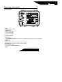
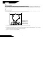
MH-10
Digital micro-ohmmeter
User’s Guide
GU-1081 / 03031601
3
∀
Safety Precautions
• This equipment should be operated only by qualified and duly trained people, closely observing the corresponding safety regulations
and instructions contained in the present User Guide.
• It should be checked that the item to be measured is voltage free.
• Before starting with the measurements, be sure that the battery is well charged and that the line voltage is between specified limits.
• Do not connect or disconnect the test leads during the measurement.
• There are no adjustable parts or parts that can be replaced by the user within the equipment. Taking out the Control Panel in order to
have an access to the internal parts may be dangerous as there are high voltages inside, capable of causing fatal accidents.
• Cleaning of this instrument should be carried out using a soft cleaning anti-static liquid, after verifying that it doesn't attack the plastic
parts used in the case and in the Control Panel of this equipment.
This equipment should be used only by a trained and competent person, strictly applying suitable safety rules.
Used symbols
∀
Caution, refer to User Guide.
#
Equipment complies with current EU Directives.
4
Index
Safety Precautions ________________________________________________________ 4
Used symbols ____________________________________________________________ 4
Description ______________________________________________________________ 6
Operating principle ________________________________________________________ 6
Operating instructions ______________________________________________________ 7
Control panel___________________________________________________________ 7
Mains supply _____________________________________________________________ 8
Measurement ____________________________________________________________ 8
Messages _______________________________________________________________ 9
Some notes about accuracy ________________________________________________ 11
Battery condition _________________________________________________________ 11
Battery and charger ______________________________________________________ 12
RS-232 output ___________________________________________________________ 12
Cleaning _______________________________________________________________ 13
Technical specifications ___________________________________________________ 13
Accessories _____________________________________________________________ 14
5
Description
The MH-10 micro-ohmmeter is a portable, microprocessor controlled instrument, used to accurately measure very low
contact resistances of breakers and switches, busbars, transformers and engines windings, etc, with test currents from
1 mA to 10 A, both in the laboratory and out in the field.
•
•
•
•
•
•
Kelvin architecture (four-terminal method).
Digital reading, alphanumeric display.
Up to 4 ½ digits readings.
Powered by rechargeable battery or mains supply.
1 µΩ Resolution.
200 Ω Maximum reading.
Operating principle
This device uses the Kelvin Bridge architecture, with four terminals, avoiding testing leads resistance to cause error
during measurement. The operator may choose test current and the reading is obtained by comparison through internal
high-stability standards. The result appears in the alphanumeric display that is very easy to read.
6
Operating instructions
Control panel
1
0
!- FUSE
∀- POWER CORD connector
#- ON/OFF switch
∃- Battery charge LED
%- Current terminal (C+)
&- Potential terminal (P+)
∋- Potential terminal (P-)
(- Current terminal (C-)
)- RS-232 output
∗- ALPHANUMERIC DISPLAY that shows both the measured resistance value and user's messages
+- START switch
,- STOP switch
−- HOLD switch. It retains the last measurement in the display
.- BATTERY. Switch to measure the battery charge condition.
/- TEST CURRENT control
0- Scale and test CURRENT SELECTOR
1- ON led
7
Mains supply
MH-10 is manufactured in different versions, to be compliant with the mains supply specifications in the destination country. Please, check the value indicated in the Control Panel in order to be sure that it is appropriate for the local A.C. supply.
Measurement
1.
Before turning the equipment on, connect the test leads to the item to be measured and to the front panel terminals.
ELEMENT TO BE MEASURED
The alligator clamps in
the drawings are only
for illustration. The
supplied clamps could
be different than what's
shown in the drawing.
2.
Using the CURRENT SELECTOR0, choose the range and the current to be used.
3.
Choose the power supply to use. If you are going to use the battery, advance to the following point. If you are going
to use the mains supply, plug the power cord into the connector∀.
4.
Switch the equipment on using the ON/OFF#.
8
5.
The PRESS START message will appear showing that measurement can be started. Press the START+ switch.
Depending on the position of the TEST CURRENT/ control the LOW CURRENT message will turn up.
6.
Turning the TEST CURRENT/ control clockwise increases the current. Adjust this control until obtaining the desired
value or until the current indicator (bar-graph) indicates 100%. The bar-graph will show the test current value as a
percentage of the nominal value selected by using the CURRENT SELECTOR0.
7.
The lowest current for measuring is 10 % of the scale nominal value. It is important to consider that the measurement errors increase while test current decreases. The error is specified for test currents higher than 80%.
8.
The DISPLAY∗ will show the resistance value measured and the corresponding unit (Ω [ohms], mΩ [milli-ohms] or
µΩ [micro-ohms]).
9.
That value can be retained in the display by pressing the HOLD− key. Pressing this key again, the value will be
erased.
10. Press the STOP, switch in order to finish the measurement.
11. Finally, when finishing measurements, turn the equipment off using the ON/OFF# switch.
Precaution: Do not connect or disconnect the test leads during the measurement.
9
Messages
CIRCUTOR MH-10
When turning the equipment on using the ON/OFF# switch, this introductory message appears for a while. During that
time, the equipment carries out some functional checking.
WAIT...
This message appears each time the equipment needs to adjust any parameter in order to optimize the readings.
PRESS START
The equipment is ready to start a measurement, thus the operator has to press the START+ button.
LOW CURRENT
It shows that the test current is not enough to carry out the reading. It appears at the beginning of each test and it keeps
on being there up to the operator rotates the TEST CURRENT/ control clockwise, as necessary for the test current to be
higher than 10 % of the nominal current in the scale. The inappropriate connection of the cables may cause a difficult
circulation of test current. If this message keeps on being displayed, please check that the current cables are connected
appropriately.
OVERRANGE
It indicates that the measured resistance is higher than the maximum value readable in the selected scale.
H
Indicates that the value is the one retained in the memory when pressing the HOLD− button.
BAT
It shows that the battery is quite discharged. The available energy is enough to work during a few minutes only. It is
necessary the battery to be recharged.
10
Some notes about accuracy
In order to obtain the specified accuracy, the operator has to adjust the test current to a value higher than the 80% of the
nominal value. If it were necessary, it is possible to use a lower current, but by doing this the accuracy will be affected.
MH-10 has an auto-compensation system that automatically eliminates the error produced by internal offset. Thus, it is
not necessary to carry out measurements by reversing the polarity in order to compute the average value. Nevertheless,
if the operator suspect that there is a difference of temperature between the contact points that would can generate
thermoelectric voltages, it is necessary to carry out two measurements by reversing the current cables and so, the circulation sense of the current through the resistance under measurement. The resistance value to be measured will be the
average between the values in one sense and in the contrary (direct and inverse current).
Battery condition
The charge condition of the battery can be verified before or during the resistance measurement. In order to achieve that,
the operator has to press the BATTERY. key while the equipment is turned on. The bar-graph shows remaining charge
as a percentile value. If during measurement the charge of the battery achieves a critical level, the display will show the
BAT message notifying that the charge level is low. After a few minutes the measurement will be automatically interrupted in order to preserve the battery from a deep discharge that is prejudicial for its expected useful life.
11
Battery and charger
Battery description
The CIRCUTOR MH-10 micro-ohmmeter uses a sealed, rechargeable, lead-acid, 12V - 7Ah battery. At the end of the
useful life, that battery has to be recycled or disposed of properly in order to take care of the environment.
Battery charger
The built-in battery charger is always active when the equipment is connected to the mains supply, even if the ON/OFF#
switch is turned off.
Charging procedure:
• Check that the ON/OFF# key is OFF.
• Connect the equipment to the mains supply.
• The indicator ∃ will keep on lightning with a red light up to completing the charge. At that point, it will change to a green
light, being like this up to the equipment disconnection from the mains supply.
RS-232 output
5 32
The equipment has an RS-232) output in the control panel that can be used to register measurements in a serial printer
or data collector. The outputs are the following ones:
Pin 2: Rx ; Pin 3: Tx ; Pin 5: Gnd;
Rate: 4800 bps
8 bits - no parity – 1 stop bit (8,n,1)
Note: In order to assure the compatibility with most printers available in the market, the resistance units are shown with the following
symbols:
uR = micro-ohm
mR = milli-ohm
R = ohm
12
Cleaning
Cleaning of this instrument should be carried out using a soft cleaning anti-static liquid, after verifying that it doesn’t affect
the plastic parts used in the case and in the Control Panel of this equipment.
∀ Replacement
fuse
To check the instrument FUSE!, remove it with a screw driver. If the fuse is ruptured replace it by another with the following specifications:
Fuse Schurter, model SPT 5x20 (Time-lag) 5A/250V. High breaking capacity H.
Technical specifications
Test currents
: 1 mA - 10 mA - 100 mA - 1 A - 10 A. Each current may
be continuously adjustable from 0 to 100%.
Resistance ranges
: 0-2000 µΩ @ 10 A
0-20 mΩ @ 10 A
0-200 mΩ @ 1 A
0-2000 mΩ @ 100 mA
0-20 Ω @ 10 mA
0-200 Ω @ 1 mA
Resolution
: 1 µΩ @ 10 A
Output voltage
: Up to 10 Vc.c. @ 1 A (open circuit)
Measurement principle
: Four-terminal, Kelvin-type.
Basic accuracy
: ±0,2 % of reading ± 2 digits
Advanced features
: Digital direct reading of very low resistances in the
alphanumerical display, with up to 4½ digits. Very fast
and accurate measurements.
Serial data output
: RS-232 @ 4800 bps. Suitable for data collection in an
external serial printer, computer or data-logger.
Environmental protection
: IP54 with closed lid.
13
Safety class
: Meets the requirements of IEC61010-1/1990, IEC
61010-1/1992 amendment 2
E.M.C
: In accordance with IEC 61326-1
Electrostatic immunity
: In accordance with IEC 1000-4-2
Power supply
: Internal battery powered. Rechargeable battery, sealed
lead, 12V - 7Ah or mains.
Built-in battery charger
: MH-10 is manufactured in different versions, to be
compliant with the mains supply specifications in the
destination country. Please, check the value indicated
in the Control Panel in order to be sure that it is appropriate for the local A.C. supply.
Operating temperature range : -5°C to 50°C
Storage temperature range
: -25°C to 65°C
Humidity range
: 95% RH (non condensing)
Maximum altitude
: 3000m
Weight
: Approx. 8,8 kg (including battery and accessories)
Dimensions
: 378 x 308 x 175mm
Accessories
• Combined current and potential leads with alligator clips 1,8m. (2)
• Charger Power cord.
• RS-232 cable.
• Operating instructions.
• Protective bag, for instrument and cable
14