1
4.3.10 CAN
The CAN controller provides all the features required to implement the serial communication protocol CAN defined by
Robert Bosch GmbH, the CAN specification as referred to by ISO/11898A (2.0 Part A and 2.0 Part B) for high speeds
and ISO/11519-2 for low speeds. The CAN Controller is able to handle all types of frames (Data, Remote, Error and
Overload) and achieves a bit rate of 1Mbit/sec.
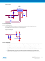
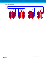
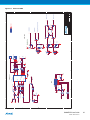
The Atmel SAM4E has two CAN Controller with eight Mailboxes.
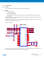
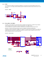
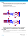
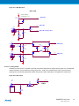
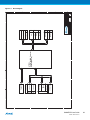
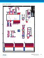
SAM4E-EK connects the CAN0 and CAN1 bus to the CAN transceiver SN65HVD234 (MN11 and MN12).
The extension connector (J13 and J14) type is RJ12 female socket.
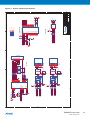
Figure 4-9. CAN block.
+3V3
R134
10K
PE0
PB2
PE1
PB3
(CANTX0RS) R135
J37-6
(CANTX0)
(CANRX0EN) R138
(CANRX0)
0R
R139
J13
MN11
8 Rs
1 D
0R
5 EN
0R
4 R
R140
10K
1
2 GND
JP28
CANH 7
2
3
CANL 6
R137
120R
4
5
6
+3V3
1
2
CAN RJ12
3
4
5
6
VCC 3
SN65HVD234
+ C95
10uF
C96
100nF
CAN0
+3V3
R141
10K
PE2
PC15
PE3
PC12
J14
(CANTX1RS) R142
0R
MN12
8 Rs
(CANTX1)
0R
1 D
R143
(CANRX1EN) R149
(CANRX1)
R150
0R
5 EN
0R
4 R
R151
10K
2 GND
SN65HVD234
1
JP29
CANH 7
2
3
CANL 6
R148
120R
4
5
6
+3V3
1
2
CAN RJ12
3
4
5
6
VCC 3
+ C98
10uF
C99
100nF
CAN1
4.3.11 Display interface
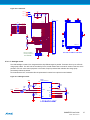
The SAM4E-EK carries a TFT transmissive LCD module with touch panel, FTM280C34D. Its integrated driver IC is
ILI9325. The LCD display area is 2.8 inches diagonally measured, with a native resolution of 240 x 320 dots.
4.3.11.1 LCD module
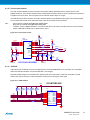
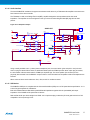
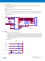
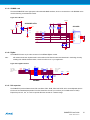
The LCD module gets reset from the NRST signal. As explained, this NRST is shared with the JTAG port and the pushbutton BP1. The LCD chip select signal is connected to NCS1; the jumper JP8 can disconnect it so that this PIO line is
available for other custom usage.
The SAM4E16 communicates with the LCD through PIOC where an 8-bit parallel “8080-like” protocol data bus has to
be implemented in software.
SAM4E-EK User Guide
42067B−SAM4E−04/2013
14