1
Installation Guide
Unit connections and features
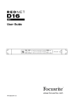
RedNet 1 - Front Panel
3
5
4
2
1.
AC Power switch
2.
Tricolour LEDs indicating signal level at each A-D and D-A converter:
1
•Green – signal level above -42 dBFS
•Yellow – signal level above -6 dBFS
•Red – signal level is 0 dBFS (digital clipping)
3.
NETWORK status flags – two green LEDs confirming network status:
•CONNECTED – illuminates when the unit is connected to an active Ethernet network
•LOCKED – illuminates when a valid sync is received via the network
4.
SAMPLE RATE indication – five yellow LEDs; only one of these (44.1 kHz, 48 kHz, 88.2 kHz, 96 kHz, 192 kHz) will be lit at a time, to confirm the sample rate that the system is running at.
5.
LEVEL SETUP indication – two yellow LEDs; one of these will be illuminated to confirm the
analogue reference level set for the unit, +24 dBu or +18 dBu. This is the analogue level which
equates to the internal maximum digital clip level of 0 dBFS.
7