1
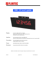
FRD – 67 user’s guide
Display
6 numeric digits of 67 mm height
High impact red LEDs with a 30° intensity cone
Automatic intensity adjustment
Interface
Field selectable RS-232 and RS485/422
Setup of communication parameters and protocol by use of a terminal/PC
Connection
Two cable glands and internal terminals
Cable diameter 6mm to 12mm
Power
100-240VAC/max 25W or 12VDC selectable
Enclosure
Lacquered steel IP65 cabinet for outdoor
©2011 Flintec GmbH reserves the right to change the specifications at any time.
FRD-67
page 1 of 4
11.02.2011/GG
IMPORTANT INSTALLATION NOTES
The enclosure must be connected to Protective Earth. This is vital for safe
operation. Failure to observe correct grounding may cause serious injury or
death. Grounding is further vital for full CE-compliance and must be
provided for correct operation.
Disconnect power when servicing the display
DIMENSIONS in metric millimeters
MECHANICAL MOUNTING
Open the front lid using a Torx TX-20 screwdriver. Internal screws are Torx TX-15 and
Philips/flat for power supply terminals.
When mounting the display, use as large as possible bolts for fixing to a rigid flat surface. If
mounting to a pole, adjust the pole flaps for a best fit to the actual pole and then tighten the
band pipe clamps (option) thoroughly. If possible tilt the display downwards and direct
toward the reader to maximize legibility. Tilting the display decreases reflections and
improves contrast. Sun hood is normally not needed.
FRD-67
page 2 of 4
11.02.2011/GG
NORMAL POWER-UP
When power is applied, the display should respond by a sequence of control messages like
software number, baud rate and address. After the short start-up formality, display is
blanked, filled with decimal points or zeroed.
For automatic settings and other controller card specific features, the behaviour may differ.
Consult the actual User's Guide for the installed card.
POWER CONNECTION
Connect the power line to the supply and make sure to use proper grounding
Check that the ground terminal on the power supply is connected to your system safety
ground.
NOTE! Unused cable glands must be blocked.
NOTE! This unit should preferably always be powered to minimize condensation
SERIAL PROTOCOL
The protocol is factory set to Norsk Display standard, fitting many vendors message format
and a good solution for an addressed data link.
Standard message without address: <STX>12345,6<CR>
Addressed message to the display set up with adr=19:
<STX><SOH>19<STX>12345,6<CR>
To reach all displays on a collective data line: <STX><SOH>00<STX>12345,6<CR>
The address ,,00" signifies broadcast (reaching all connected displays)
All exemplified messages will result in the message ,,12345,6" on all addressed displays.
A Windows™ Utility program is available on Norsk Display Web page www.norskdisplay.com
Highly recommended for safe setup of parameter
FRD-67
page 3 of 4
11.02.2011/GG
IMPORTANT MAINTENANCE NOTES
Disconnect power when servicing or maintaining the display !
MAINTENANCE
Normal maintenance includes washing off dust with a well wetted cloth. Use plenty of water
with a mild detergent to avoid scratching the surface.
REPAIR
All parts of the display are field repairable. You are however adviced to contact factory for
specific instructions for repair. Make sure you maintain all approvals when replacing failing
parts. Factory repair ensures a period of 12 months limited warranty.
www.flintec.com
FRD-67
page 4 of 4
11.02.2011/GG